Film cameras
Air Force Gun Sight Aiming User manual
User manual for Air Force Gun Sight Aiming. 11 pages in English. Read the original PDF, download or print a copy without registration.
11 pagesEnglish5.1 MB PDF
Loading your manual…Open PDF directly
Document details
- Brand
- Air
- Model / document
- Air Force Gun Sight Aiming
- Document type
- User manual
- Language
- English
- Pages
- 11
- File size
- 5.1 MB
- Category
- Film cameras
- Document date
- Not specified in catalog
Search available document text
Find a term, then jump to its page in the original PDF. Image-only pages may not be searchable; check the PDF for exact wording and diagrams.
Page 3 · Read text
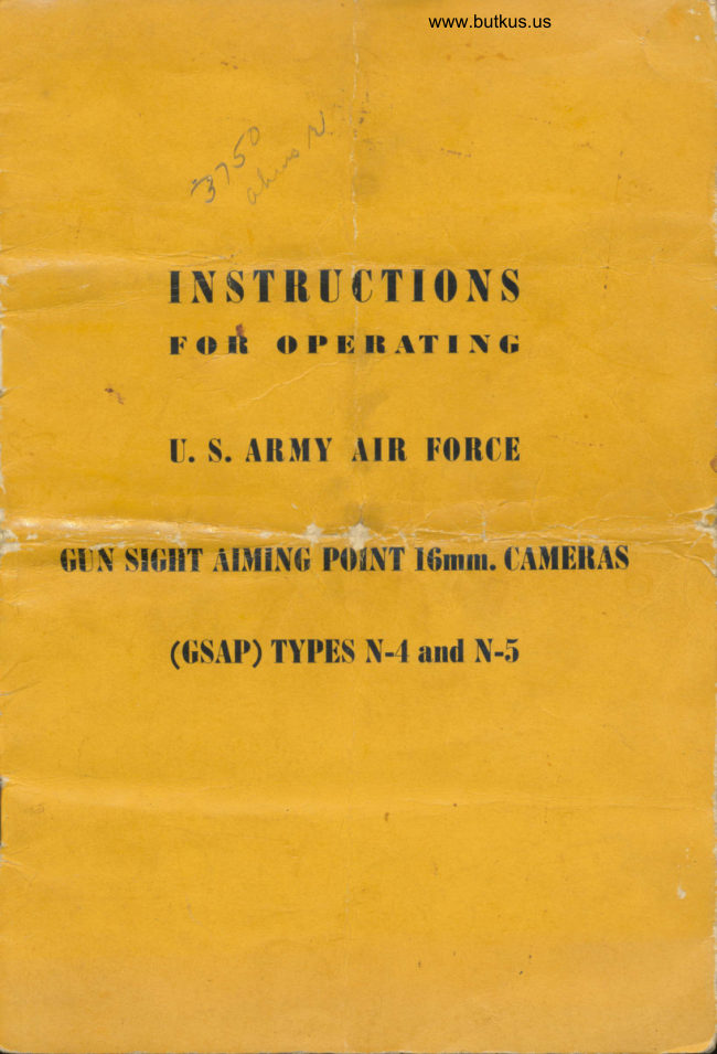
Instructions for Operating
                 U. S. Arrny Air Force
       Gun Sight Airning Point 16rnrn. Carneras
              (GSAP) Types N-4 and N-5

          The camera types differ only in lens   hazard, burnt-out motor, etc. A
          equipment, as follows:                     description of porver connections and a
       Camera  l/oltage oJ                      wiring diagram appear on page 6.
           Tylrt     Motor          Lens
        N-4     24-volt   35mm., plairr   LOADING THB CAMERA        N-5      24-volt   35mrn.. 90"                                       The GSAP Camera uses film which                                   erectlng systeln                                                                            is pre-threaded in metal magazines. To
                                                   load the camera,  lift the spring latch A,
     POWER                            Figure 1, and open the door. Insert the                                                  film magazine B, Figure 1, as illus-
          The Bell & Howell GSAP Catncra is   trated, making certain that
           driven by an electric motor. A thern-ro-       (1) the opening in the film magazine
             stat automatically cuts out the motor if   gocs in  first;
         improper threading of the film maga-      (2) the pin on the edge of the maga-
           zine, or any other factor, should cause   zine faces arvay from the cable re-
         the film to jam, thus eliminating frre   ccptacle; and,


               www.butkus.us


                                                                                            s,
II
t
:
F


  I                                         Figure I
                                     Inserting filrn rnaga zine
                             A. Door latch     B. Filrn rnagazine
                                                                .l


,t
li
1!t:l-
View original page 3Page 4 · Read text
www.butkus.us


                                     Digitally signed by mike butkusmike               DN: cn=mike butkus,
                             o=orphancameras, ou=29,
                              email=mike@butkus.org, c=US
                                Date: 2020.03.14 19:39:49 -04'00'butkus


                                  Figure 2
           C. Speed control knob          G. Lens
          D. Speed index rnark            H. Lens sheath
           E. Footage indicator knob         J. Lens rnounting strrds            F. Footage dial                K. Lens heater pin jacks

      (3) the footage dial on the rnagazinr:  FOOTAGE INDICATOR   (which is not used  i r  this canera)  is
                                                                                                 'i iie footage dial on the GSAI,   toward the outer face of the camera.
  and not toward the interior. Push the  Camera is external; the dial on the
                                                                                    is not used. When the loaded  magazine forward until there is an   magazine
   audible click; then close the door.       camera is ready for operation, turn the
                                             indicator knob E, Figure 2, until the
                                             lootage dial F, just below, indicates 0,
 SPEED CONTROL                       if a full magazine is to be used. lf the
                                               film magazine is not full, set the indi-     This camera operates at any one of
                                           cator to correspond with the figure on  3 speeds    76, 32, or 64 flrames (ot             -                         the magazine footage-indicator dial.   pictures) per second. Thc motor                                       Hencelorth during that film run, thc   operates at a constant speed, and the                                             dial will indicate the amount of filrn   various camera speeds are achieved b1'                                                                                      stil I remaining unexposed.  changing the gear ratios. To set the
  camera speed, turn the speed control
  knob C, Figure 2, until the index mark  THE LENS   for the desired speed figure on the dial
   is opposite the fixed index mark D,   I\Iethod of Mounting. The Lens G,
   Figure 2, on the camera.                 Figure 2, is permanently mounted with-
                                        in the heavy, protective, sheath-and-
  IMPORI'ANT  z Do not change speed while   flange unit H, Figure 2. The lens is
   thc camera is in opcration.                mounted on the camera by fitting the
                                       '2.
View original page 4Page 5 · Read text
single index mark O, Figure 3. Collar Q
                                             rotates, and bears the exposure s)'m-
                                           bols B, H, D, and 3.5 on its rear edge
                          M, Figure 3, and the camera speed
                                            figures 76, 32, and 64, on its forward
                                      edge N, Figure 3. Collar R is the dia-
                               phragm adjustment. It also rotates,
                                   bearins the single index mark L,
                                        Figure 3.
                                 To sct the lens, rotate collar Q until
                                           thc indcx mark for the desired camera
                                      speed N, Figure 3, is opposite the fixed
             Figure 3                 index mark O, Figure 3. Then rotate
                                           collar R, until the diaphragm index
Detail of lens adjustrnerlt. Lens   rnark L, Fieure 3, is opposite the sym-
(with 90" erecting s.vstern) is set for   bol for thc light conditions of the
eamera spet:d of 16, rrnrler dull light-   rrroment. The lens shown in Figure 3
ing conditions                                     is set for rvork at 16 frames per second
                                   on a dull duy. Figure 4 shows the plain
 L. Diaphragm intlex rnark              lens set for operation at 64 speed on a
M. Exposure syrntrols for lighting   hazy duy.    conditions
N. Carnera speed figures
O. Fixed index rnark
 P. Fixed index collar
Q. Rotating speed and light collnr R. Rotating diaphragrn colllr
 S. 90" erecting systern
flange over the three dowel studs .f,
Fieure 2. When changing lenses, ttse
the wrench Y, Figure 7, and be sttt'e
that the flange is flush with the catrtet':r
housing before tightening the nuts otl
the dowel studs.
Adjusting the lens. Both types of
lenses are 35mm. in focal length, with a
maximum aperture of  f i3.5. Each type
is adjusted in the same manner. Two
lens adjustments are necessary, one for
the camera speed-76, 32, or 64 frames
per second-and one for light condi-
tions-B (bright), H (hazy), and D                  Figrrre 4
(dull) , or f/3.5 (for adverse light con-    l'lain lens set for work at 64 frarnes
ditions).                                          l)er second on a hazy day
  These adjustments are effected with
the three lens collars P, Q, and R,    No additional lens adjustment need
Figure 3. Collar P is fixed, attd bears a   be made for the filter, since its factor
                                    .3.
View original page 5Page 6 · Read text
www.butkus.us

                                                     is compensated for in the lens calibra-
                                                   tions.
                                                  'l'he Lens rvith 90o Lrecting Systerrr.
                           The lens on Typ. N-5 Camera is
                                     equipped with a 90o erecting system S,
                                       Fisures 3 and 5, which deflects the
                                      photographic aim of the lens by 90o.
                               For example, with the lens pointed
                                          vertically upward, the photographic
                                    aim is on a horizontal plane.
                       www.butkus.us          'fhe erector is affixed to the outer
               Figrrre 5                    flange of the lens sheath by 3 scrervs V,
                                        Figures 5 and 6, which will fit in any   Lcns with 90o ereeting systern                                              of 4 threaded holes X, Figure 6, which
 S. 90'ereeling systern                 are tapped at quadrants about the cir-
T. Lcns                               cumfierence of the lens flange. Thus,V. Scrcrys. which are rernovetl wherr                                    rvhen the screr,r's are removed, as in    crecting systern is to be shiftedW. Filtcr                             Figure 6, the photographic aim may
                                   be changed, at intervals of 90' in the
                                    sarne plane, by aiming the erecting
                                    system in the desired direction and
                                        replacing the screws.
                                 The3filter W, Figure 5, is removable.
                                                 Figure 7             Figure 6
     Erecting systern rernoved            Plain lens, with filter rernore.d              I
   3 screws                     W. Filterv.x. 4 equi-distant screw holes, for   Y. Wrench, to be used in changing
    resclting the erecting system at       lenses   intcrvals of 90" on the  sarrle
   plane                              Z. Dust cap
                                     .4.
View original page 6Page 7 · Read text
The Plain Lens. The plain lens on  from becoming frost-covered in ex-
        Typ. N-4 Camera (see Figures 4 and   treme cold, the heater cord should be
         7) is the same as that on Type N-5   plugged into the pin-jacks K, Figure 2,
          except that there is no erecting system.    rvhich are provided for this purpose.
          Therefore, the photographic aim is on
          the same plane as the axis of the lens.
        The plain lens is equipped with a filter  FIDUCIAT MARKS
        W, Figure 7, which is removable.                                               While no reticle pattern has been in-
         Interchangeability. Both types of   corporated in the optical system of the
         lenses are interchangeable on both   camer a, the photographic aperture has
          types of cameras. But, erecting system      lre en provided u'ith trvo pairs of fiducial
        and filter are not interchangeable and   marks which will be visible in each
            will not fit both lenses described herein.   frame of exposed film. One pair of
      IMPORTANT: Neaer attempt to dis-   these marks is located on the horizon-
           assemblc the lens or the erecting system.           tal plane on the center line of the frame,
                                     and the other pair is on the exact
                                                         vertical center line of the frame.
     THE FITTER                                    It will be observed that rhe crosslines
          Each lens is equipped with an amber   of the aligning indicator align them-
            filter having light transmission char-    selves with the fiducial marks irr the
            acteristics equivalent to a Wratten No.    aperture.
       12 (minus blue) filter. The filter
          should be left in position at all times,
          except for cleaning, for two reasons:  ALIGNING INDICATOIi
              (1) lens adjustments are calibra',:i to
         compensate for the increased exposure
          required when a filter is used, and
            (2) the filter will prevent dust and
           dirt from reaching the optical surfaces
           in lens and erecting system.

     HEATING UNITS                                Figrrrc lf
                                                      Aligning indicalor         To prevent lreezing at high altitudes,
           the camera is eqrripped rvith a therrno-             C. B1'epiece
           static heater, which, dowrt to a mini-
      mum of 40' F. below zero, automati-                                         The aligning indicator, Figure 8, for          cally maintains the intcrior of the                                              the GSAP Camera is designed to fit        camera at a temperature between 35oI                                               into the chamber ordinarily occupied           F. and 95' F. The heater starts operat-                                           by the film magazine. Insert the indi-
T        ing when the temperature drops below                                                      cator as shown in Figure 9, the rounded
         35' F. and is cut out if the internal   end going in first, and the flat, solid side          temperature rises to 95' F.                                                             of the indicator facing the outside of the
               If an external, lens-heating unit is   camera (the door-hinge side). Push the
            to be used, to prevent the glass surfiaces   indicator in as far as it will go.
                                                .5
View original page 7Page 8 · Read text
www.butkus.us

                                                   Figure 9
                                              Inserting :rligrring irrrlical<lr


         www.butkus.us
                              Thc eyepiece C, Irigurc 8, of  tlrt'
                                       optical system will  rota te  tlrroug,*lr
                                           360", and may be used in any yrosition.
                                   The eyepiece may be detachecl li'om tlrc
                                             indicator simply by pulling  it out, arrcl
                                       care should be taken that when it  is
                                         replaced, the tube is pushed into tlre
                                          indicator up to the hilt, in order to
                                    engage the spring button (within the
                                              indicator) with the groove on the tube.
                                    The cross lines of the aligning indica-
                                         tor are adjusted in manufacture  to
                                        correspond with the fiducial marks of
                                    the photographic aperture. If the
                                          cross lines do not coincide with the
                                      camer-a fiducial marks, the camera
                                      should be turned in to an overhaul
                                                       aci'r it)' for checking and adjustment.


                                                ,, h EAIER THERMO5T\]


                                     Figtrre l0
                     Wiring diagrarn for cantera
Frorl the 4-prong receptacle on the carnera, a line cable goes to tlre stiek
             control srvilch atrd thencc to the source of power
                                     .6.
View original page 8Page 9 · Read text
so that movement within the     CARRYING CASE               each unit,
                                                case is reduced to a minimum. Each
        The specially built carrf ing case   unit should be packed in the case as
          provides compartments designed to fit   shown in Figure 1 1.


                                      Figure ll
         Carryihg case, with various units properly fitted into their cornpartrnents
               B. Filrn rnagazine      AA. Receptaeles for extra lenses
            W. Filter             BB. Aligning indicator
               Y. Wrench           CC. Instruction book
                Z. Dust eap          DD. Extra identification cards
                                 EE. Canrera
I:L    CAMERA MAINTENANCE    Cleaning. Cleanliness  is an important
                                                               successful operation         Lubrication. The camera is com-  factor in the
           pletely lubricated when it leaves the  of any motion picture camera. While
          factory, and no further lubrication the lens, erecting system' sunshade,
         of any part is necessary. Lubrication and filter are removable, no further
          will be checked and renewed when disassembly of lens or erecting system
          necessary, when the camera is over- should be attempted. The fi.lter and
       hauled.                                  the outer lens surface should be cleaned
                                            -7-
View original page 9From the M. Butkus archive. Original publisher and archive notices are retained.
Check the model and edition against your equipment.
PDF verified 2026-10-10.