Film cameras
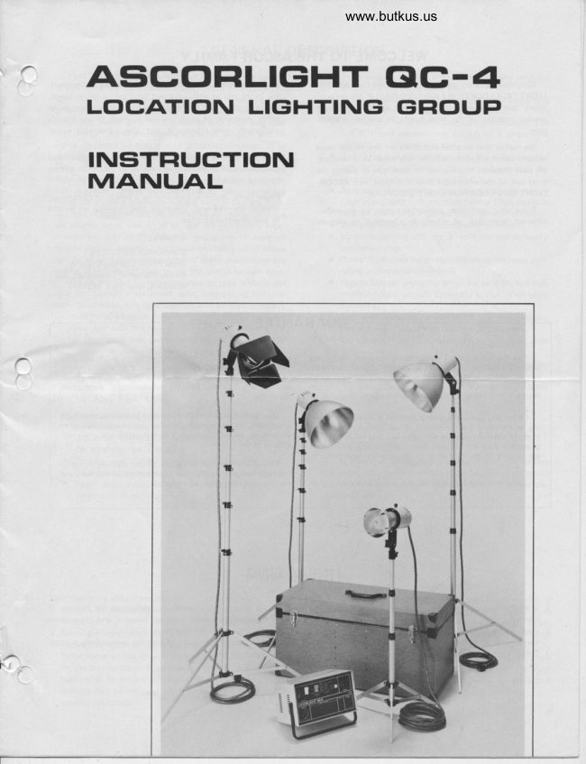
Ascorlight QC-4 User manual
User manual for Ascorlight QC-4. 13 pages in English. Read the original PDF, download or print a copy without registration.
13 pagesEnglish2.4 MB PDF
Loading your manual…Open PDF directly
Document details
- Brand
- Ascorlight
- Model / document
- Ascorlight QC-4
- Document type
- User manual
- Language
- English
- Pages
- 13
- File size
- 2.4 MB
- Category
- Film cameras
- Document date
- Not specified in catalog
Search available document text
Find a term, then jump to its page in the original PDF. Image-only pages may not be searchable; check the PDF for exact wording and diagrams.
Page 3 · Read text
www.butkus.us

                GENERAL DESCRIPTION
    Your Ascorlight OC-4 Location Lighting Group consists             .  Four plug in printed circuit boards make servicing
  of a portable 400 watt second power supply with power and              simple and minimize down time.
 sync cords; four universal  light heads with reflectors, flash             .  Circuit breaker system for the main input power line
 tubes and modeling lamps; a 4 way barndoor for the hair-               eliminates troublesome    f use changing.
  light; four heavy duty folding stands and a carrying case.             .  Symmetrical or asymmetrical light distribution. The
   Two '12" lights are usually employed as main and fill                 full 400 watt seconds may be put on a single light
  lights. Designed for high quality professional  results on lo-              without any external adapter
 cation as well as in the studio, these reflectors give the high-      a  1, 2, 3, or 4, light operation with the widest range of
  lights so necessary for top quality key liqht, yet retain the                lighting ratios available at the turn of a switch. No
 softness desired for adequate fill illumination. Long  life,               accessory power plugs are required.
 high intensity, quartz halogen modeling lamps inside the      a Accessory automatic audible alarm indicates  fail to
  flashtube assure a modelinq pattern exactly like the flash.               flash in any light or if you flash before 100% power is
 For ease of replacement, the flashtubes and modeling lamps               reached. Doubles as a camera mounted control,center,
 are plug-in types. not wired in, and are completely inter-      a Universal lights with interchangeable reflectors.
 changeable with all the lights in this group. A standard             .  Umbrella lighting with the S" reflector and acce$ory
 double contact bayonet base on the modeling lamps allows              umbrella clamp.
 you to select from a large number of lamps available on the      a Ouartz flashtubes for greatest  life under the most pun-
 market if you do not wish to use the quartz halogen type.                ishing professional conditions.
   One of the two 5" reflectors may be used without the      o Ouartz halogen modeling lamps for long life and high
 four way barndoor for broad, even, background  illumina-            modeling light output. Especially useful when using
 tion. In addition. this light may be used with an accessory               umbrellas.
 umbrella for soft bounce light.                       a Low cost, standard parallel blade sync cord permits
   When used with the four way barndoor, the other S,, re-               fast and easy location replacement  if necessary.
 flector becomes a well controlled edge or hair light. The      a No stand-by heat. Can be left on continuously with
 four tapered doors close down to the smallest opening to           no overneatng.
 assure lighting only the area you desire. 3600 rotation of      a Fast recycling. 1.2 seconds to 100% light output on
 the reflector allows it to be used in anv position.                  full power.
                                         a Three recycle rates allow use in areas where power  is
 IMPORTANT FEATURES                                               limited.
    .  Power supply utilizes slid state circuitry with auto-
      matic voltage regulation for uniformity of exposure
     and color temperature regardless of fluctuations  in
       the incoming  line voltage.                        APPLICATIONS
  a  lsolated, low voltage trigger circuit eliminates shock           The advanced design and portability of the QC-4 location
      hazard and damage to delicate shutter contacts.          Lighting Group make it ideal for production school photo-
  o Ready light indicates 100% of capacitor charge for          graphy, industrial studio and location work, and police iden-
      uniformitV of exposures.                                            tification photography.


                     PREPARATION
Assembling the system for use.                                       4. Attach two 12" reflectors to the light heads on two of
1. Remove the equipment from the carrying case.                      the tall stands. See figure 2. Attach two 5" reflectors to
   See figure  1.                                                      the two remaining  lights. To attach the reflectors, loosen
2. Set up the light stands.                                             the retaining screw located on the top of the front edge
3. Secure the lights to the appropriate stands as follows:             of the light head. lnsert the collar of the reflector fully
   Three lights on the longer stands and the remaining light               into the front of the light and tighten the retaining screw
  on the shorter stand. Note that the lights have a reducer                until the desired degree of friction is obtained. The tight-
   bushing to fit on the %" folding Stands included. This                er the screw, the more resistance there will be to rotation
   bushing may be removed for mounting on 5/8" or 3/4"              of the reflector.
   studio tvpe stands.
                                                                                                             3
View original page 3Page 4 · Read text
Venmo @mike-butkus-camera  Ph. 2083
PayPal Name  Lynn@butkus.org      www.PayPal.me/lynnbutkus
View original page 4
Page 5 · Read text
Figure 2. Ataching reflector to light head .


 Figure 1, OC4 Lo@tion Lighting gtoup packed  in carrying case.

5. Install one modeling lamp and flashtube in each of the
    lights. See figure 3. The modeling lamp bayonets into the
   inner socket. When using quartz halogen lamps, do not
   handle the quartz portion of the lamp with your bare
   fingers. Use the protective paper supplied with the lamp,
  a clean piece of cloth, or other suitable material. The
   flashtube plugs into the three holes in the main scket.
   Since the flashtube prongs are keyed, the flashtubes can-
   not be inserted incorrectlV.

     CAUTION: HANDLE LAMPS WITH CARE!
      Always disconnect  light head cord from power             www.butkus.us
                                                lamp.                                     replacing                    removing             before                         or      supply                                                                                           Figure 3. Inserting modeling lamp using protector cloth.                                            Because                                   handling.                           before                 to cool      Allow lamp
      lamps can break  if put under stress, always han-
       dle them cautiously and gently. Use gloves to               7. Plugthe male end of the sync cord supplied into the sync
       prevent iniury to hands  il glass should break                    recepticle located on the top of the power supply. The
     Some lamps have keyed pins; make certain pins                  female end is connected to the camera svnc cord (not        are aligned against socket before attempting to                                                                       supplied) and the entire assembly is then connected to        insert lamps.
                                                                     the camera sync outlet.
 6. Connect one 12" light and one 5" light to power outlets         8. Check the power supply and make sure the on-off switch
  A and B on the top of the power supply and one 12"           and modeling light switch are in the off position. lf you
    light and one 5" light to outlets C and D. See figure 4.             are uncertain about the capacity of the power line to be
  NOTE: When using the system connected as in step 6             used, start with the charging speed switch in the slow
   above and the power supply is in the symmetrical posi-              position. Attach the AC power cord to the power supply
    tion, each light will have 100 watt seconds. Befer to the             input socket. Connect the other end of the power cord to
   table on page 8 for other combinations of light out'           an adequate AC outlet. See the power supply specifica'
   put. The two assymetrical  distributions  available with            tions for the current requirements at various charge
   the OC-4 power supply allow a great variety of lighting             speeds. Note that a 3 prong plug is used for safety. Do
    ratios.                                                        not remove the grounding prong.


A
View original page 5Page 6 · Read text
www.butkus.us

                         OPERATION

         INITIAL PROCEDURE                                            2. Turnthe power supplyon and allow a few seconds for
                                                                            the ready light to come on. This procedure may be             With the system assembled as in "Preparation", page 3,                                                                           performed with the power supply in high or ratio             proceed as follows.
                                                                                   power.
             Turn the on-off switch on the power supply to ON and                                                                                  3, Set camera shutter at its highest synchronizing speed             allow the unit to charge until the ready light is on, indicating                                                                                 and the lens opening to its widest position.             the power supply is 1007o charged. The lighting group  is now                                                                                  4. Set synchronization on lens or camera body to X.             ready to flash either through the push-to-flash button or the                                                                                        5. With the camera and light unit pointed at a light sur-           camera sync contacts. To activate the modeling lamps, turn                                                                                                        face, look through the camera lens and trip the shutter.            the modeling light switch on. Power level and lighting ratio                                                                  The short flash duration makes it possible to observe             selections may be made at this time.                                                                                  the exact position of the shutter leaves at the instant
                                                                                           of the flash.  lf the shutter is in synchronization,  a per-
       SYNCHRONIZATION                                                  fect circle will be observed.  lf this does not happen
           To check flash synchronization, perform the following             the shutter synchronization  circuit of the camera
            orocedures:                                                        must be checked and repaired.
                1. Open the camera back and remove the ground glass if
                  so equipped.


                                                                                                                                                              Digitally signed by Mike Butkus
                                                                                                                      DN: cn=Mike Butkus, o=Butkus camera
                                                                                                                                 manuals, ou=butkus.org, email=mike@butkus.                    Mike Butkus  org, c=US
                                                                                                                                          Date: 2023.02.20 20:24:08 -05'00'


t'

                                                    Figure 4, Front panel of the OC-4 Power Supply showing layout ot controls
View original page 6Page 7 · Read text
\
OC CONTROL CENTER (optionall                  USE OF AN UMBRELLA  (optional)
   With this optional fail-to-flash indicator and remote con-           Most umbrellas can be used with the Ascorlight OC-4 in
trol center, {see figure 5} a really fool-proof audible and vis-        conjunction with the 5" light. In order to mount the um-
ual system will warn the photographer  if a picture is taken          brella to the light, an umbrella mounting clamp must be
before the 10096 ready light is on. Automatic Fail-to-Flash        usd. See figure 6.
Circuits are also employed on all four outlets in use with any         To mount the umbrella clamp to the 5" light, remove
and all combinations  of lights and ratios. Failure of any light        the bolt that passes through both sides of the clamp. Slip
to fire will als sund the alarm. Thee safeguards coupled         the open end of the clamp over the light mounting bracket
with completely automatic voltage regulation assures the       on the side away from the light adjusting knob. Re-insert
ultimate in exposure consistency from exposure to expo-         the bolt through the umbrella bracket so that the bolt  is on
sure. When the NOT READY ALARM sounds,  it will be         the outside of the light bracket and the formed ends of the
necessary to momentarily push the reset button to stop         umbrella clamp are on the inside of the light bracket. Be-
and reset the alarm. The circuit is automatic regardles of          fore tightening the bolt to secure the clamp, align the clamp
the number of lights used. Other features of this accesory         so that the edge of the reflector does not interfere with the
include a push-to-flash button, a sync outlet, and an on-off         umbrella shaft. After tightening the bolt on the umbrella
switch for the fail to flash operation.                             clamp, the umbrella shaft is ins€rted into the clamp after
  To us the control center accesry, simply plug it into          loosening the retaining knob. After the umbrella is in the
the fail to flash outlet on the front panel of the power sup-          desired position, the knob can be tightened to secure the
ply and turn the on-off switch to the on position. Any lights           shaft.
plugged into the power supply will then be connected to the
fail-to-flash  circuit.  lf a visual alarm only is desired, turn the
audible alarm witch to the off position.
                                                                                                 -'


              Figurc  5. A@6ory OC Control C.nter.                                      Figure 6. OC-4 Light with Umbrella and Clamp,


                                                                              +\:
View original page 7Page 9 · Read text
I


 FLASH DURATION                          ^J   The old method of measuring flash duration of a flash
 unit was to measure the time between the one-third points
 of peak light intensity. This method has been further broken
 down into two classifications, Effective Flash Duration and
 Total Flash Duration. The method for determining  the val-
 ues is the same. The only difference is that Effective Flash
 Duration is measured from the % or.5 point of peak light
 intensity and the Total Flash Duration  is measured from                                            Etfective Flash Duration
 thel/2O or.05 point of peak light intensity. Effective Flash
 Duration is usable for exposure purposes, but total flash
 duration should be used to determine the relative stopping
 action of the flash as compared to a mechanical shutter, All
 three methods of flash duration measurement were made
 with the QC-4 and the results appear in the table below
 alcng with an explanatory diagram of flash duration
 measurements.                                                                                          Figure 9. Flash duration.
                                 TABLE II
                                   OC.4 FLASH DURATION                  (Fractions of a Second)

       METHOD OF       MEASUREMENT              50 ws        100 ws      133 W-s       150 W.s      200 ws      300 ws      400 ws

     EFFECTIVE               FLASH                             U1200       1/820       1/750                    | /700                     | /620       1/470                   't 1370                     1/2                   POINT    DURATION

     TOTAL FLASH
                                                                                                                                                                                                             1 /120    DURATION 1/20 POINT         1 1450       1/320       1/300                 | /250       'v220       1/180

 OLD IMETHOD
                                                                                                                                                                                                              1 /250 OF MEASUREMENT  I/3 POINT    1/870       1/620        1/550        1 1470      1/420       11320

POWER SELECTOR CHART
   To assist you in determining the light output of the QC-4           outlines the power distribution with different selector
 lights when using various ratio powers, the following chart            switch settings and different combinations  of lights.

                                 TABLE III
                POWER SELECTOR CHART FOR OC-4 POWER SUPPLY

 POWER SELECTOR                     NUMBER OF            CHANNEL  1               CHANNEL 2
                                               PER                      DISTRIBUTION        LIGHTS                                                                         FE-_-----llllr|  SWITCH SETTING                                     CHANNEL                                                  WATT                                                            SECONDS PER LIGHT   WATTrr--I'_lSECONDS PER LIGHT
    Posrtron         une
            z       2 Separate Channels        one                     200                        100     lT6"l
     [-65-l  r          (AsVmmetrical)          two              100            100             50          50
    Pl      r10n   I         wo                   2 Separate Channels        one                     300                           t00           s     TE-l
    cDt  1           (Asymmetrical)           two              150           t50             50          50
                                           one                                   400
                  Combined Channels      MO                                   200 each
                         (Symmetrical)
                                                    three                                                                    1 33 each
                                                        fou r                                     100 each E-
I
View original page 9Page 10 · Read text
www.butkus.us

          USE OF AN ELECTRONIC FLASH METER

   The ure of an electronic  flash meter can greatly simplify           Most important to creative photographers,  the Gossen-
 exposure determination,  expecially when using multiple        Arcor E.F. meter can compute the cumulative  light output
 lights or indirect lighting. A good flash meter will give you a          of entire sries of successive flashes used for "painting with
 direct reading in f/stop for the type of film and particular           light" and similar special applications.
 lighting st-up usd, eliminating guesswork.
                                                                  Designed and manufactured by GOSSEN, the meter is
  An exceptionally verstile and accurate electronic flash         completely slf-contained, weighs only 9 oz. and fits the
meter is the Gossen-Ascor electronic flash meter. lt  is all         palm for convenient one-hand operation.
 solid state, battery operated, and requires no direct connect-
 ion to the power supply. Incandescent and other con-          The operation of the Gossen-Ascor meter is extremely                                                           simple and positive. The two-position toggle switch  istinuous light sources do not affect the reading. This feature
 is especially important with today's high intensity quartz-          pressed backwards to cancel any previous measurement.
halogen modeling lamps.                                       Held (or tripod-mounted) at the subject position, the meter
                                                                        needle deflects at the instant of the flash and remains locked
                                                                         at the measured value. The adjacent computer  dial indicates
                                                                  the exact f/stop for correct exposure. The computer ring  is
                                                                         adiustable for ASA film speeds from 6 to 6400; the f-stop
                                                                       scale is calibrated for all stops from f/l  to f/90 with 1/3
                                                                      stop Increments.

                                                            The solid-state circuitry (pat. appl. for| includes a silicon
                                                             sensor which opens the measuring circuit automatically
                                                                        within one microsecond by means of a transistorized  trigger-
                                                                ing circuit. A color-corrected photo transistor within a
                                                                    hemispheric diffuser integrates the light of the flash and the
                                                            ambient light in a transistorized integrating  circuit. The re-
                                                                         sultant reading can be read critically and without parallax
                                                                   error as the needle image is reflected in an underlying
                                                                       mirror surface.
                                                                            Individual flash measurements can be made in ouick
                                                                   succession by pressing the toggle switch after each me_asure-
                                                         ment, returning  all circuits, and the indicator needle, to
                                                                     zero, and starting a new measuring cycle. However,  if un-
                                                                         interrupted, the instrument remains in measuring condition
     Figure 10. Go$n-A$or Automatic  Electronic Flash Meter.                for a three-minute  period during which successive flashes are
                                                                    automatically added to the result of an initial flash reading.
GOSSEN-ASCOR AUTOMATIC                                     After three minutes, the instrument switches itself off auto-
ELECTBONTC FLASH METER                                   matically to presrue battery life. With normal use, the
   The new GOSSEN solid-state electronic  flash meter pro-          Eveready No. 504 battery lasts for sveral thousand  read-
vides the professional photographer with an exceptional             ings. A built-in battery testing circuit is operated by press-
combination of advanced features for fast and accurate             ing the switch forward.
f lash exposure determination,
                                                                                           Its compactness, fast operation and adaptability to cum-
  The meter is cordless;  it starts measuring automatically           ulative flash measurement make the Gossn-Ascor meter
within 1/1,000,000th sec (one microsecond)  at the thresh-            ideally suited for the active studio employing electronic
old of the flash.                                                                 flash.

    Its wide measuring range is spread over a single broad          The meter is supplied in a protective storage case, com-
*ale, thus eliminating the need for test measurements or           plete with an adiustable neck strap. lt is available at better
circuit switching even when unknown flash intensities  are        €mera $ores,
useo,
View original page 10Page 11 · Read text
i

                                                                                                                                                                                                                                                                                                                                                                        I
       CARE AND MATNTENANCE OF THE EOU|PMENT
                                                                           4 _r)  Although the ASCORLIGHT OC-4 Location Lighting        5. DON'T  - Attempt to open or make repairs to ASCOR-                                                                                                                                                                                                                                   'Group is a ruggedly built electronic assembly, it should be          LIGHT units if you are not familiar with electronic
handled with the same care given any piece of quality equip-            equipment. Your dealer should be consulted regarding
ment, To be assured of maximum, dependable seryice, the              our Authorized Service Station in your area.
photographer should observe the following precautions:       6. DON'T - Place a hand or objects near any part inside
   1. Avoid bending the cables sharply. Too sharp a bend            the Power Supply case until you are certain that the
      can break the wire in the cable.                                        capacitor bank is fully discharged.
   2. lf cable becomes frayed orconnectorsdamaged, have         7. NEVER use a higher rated fuse than recommended
     them repaired immediately                                    8. Rember all ASCORLIGHT equipment is designed to
   3. Keep all connectors free of dust, moisture, and           be SAFE when used in accordance with instructions.
    corrosion.                                                  9. When not actually using your ASCORLIGHT equip-
   4. DON'T - Insert a screwdriver or other metal object in-             ment,  it is advisable to turn  it "OFF."
      to the Power Supply case, flashtube socket, or power
       outlet. contact with high voltage may resu lt.


GENERAL SERVICE INSTRUCTIONS
                Trouble                                                            Possible Cause
 1. The unit does not trigger from the camera, but triggeB      1. Camera shutter contacts bad.
   from the "Push to Flash".                                 2. Svnc cord bad.
                                                                3. Svnc cord connections bad.
2. The unit does not trigger from the camera, or from          1. Reverse the sync connection  to the camera and try again.
   "Push to Flash" button.                                 2. Remove the sync cord and push the push to flash button,
                                                                                                        lf no flash occurs, one of the following  is bad:
                                                                      a) flash tube
                                                                      b) trigger coil - in the light
                                                                      c) trigger circuit in power supply on circuit board
3. The modeling  light stays off with modeling control on.       1. Check the modeling fuse.
  AC on-lamp  is lighted. Ready light  is on.                     2. Check the modeling lamp.
                                                            3.  lf the lamp  is still off, then power supply should be
                                                                         repatred.
4. ACon-lampisliqhted,butnoreadylight.            1. Pushthe"PushtoFlash"button.   lf theunitflashes,ready
                                                                                         light circuit could be defective.
5. Power cord is connected, AC on-lamp  is off. No                     1 . Check power cord connection.
   modeling light.                                             2. Check the fuse or the circuit breaker of the wall outlet
6. Modeling light is on. AC on-lamp does not lighl                     l. Reset the 15A circuit breaker by pushing it down.
7. Buzzer goes on in OC control center.                      1. Power supply fired before 100% ready.
                                                           2. Flashtube defective.
                                                           3. Light or power supply defective.


                                                                                                                                                                                                                       t-                       4


                                                                                                                                                                                                             4

                                                                                                                                                                                                                                    JIl
View original page 11Page 12 · Read text
www.butkus.us

(*r
      /       NOTE: Although service should nerrer be attempted by         2. Holdover board. Labeted "HOLDOVER pC-2,'. This
I             an un-experienced person, servicing of the OC-4 is simpli-          board prevents the flashtube from ',holding-over,. or
.              fied by having four printed circuit boards. These boarqs             "after-glowing".  Without this feature, a fast recycling
              perform different functions and facilitate location of a           power supply can cause a flashtube to continually glow
 .            problem  if one should ever occur. The boards are as          which will damage both the tube and power supply.
                 follows:                                                     3. Power supply. Labeted "POWER SUppLy pC-3,.. This
            1. Regulator board. Labeled "REGULATOR pC-1". This           board supplies the operating voltages to all the internal
             board controls the operating voltage level of the main             control circuits.
             energy storage capacitors and prevents light output          4. Trigger board. Labeled "TRIGGER  PC-4',. This board
             changes with fluctuations in incoming line voltage.             supplies the triggering pulse to fire the flashtubes in con-
                                                                                     junction with the camera shutter contacts.


             ACCESSORIES AND REPLACEMENT PARTS

             For catalog numbers and prices, please consult the latest        12" Diffuser
            Ascorlight QC-4 price  list.                                                                    For added softness. Can be attached either directly to
                                                                    12" Light Assembly or can also be used in conjunction with           Umbrella Clamp and 44" White Umbrella                                                                             the 12" Barndoor. 47% transmission.  (1,f/stop).
           "The larger the light source. the softer the shadows.,,
         The Umbrella is probably both the oldest and newest way         2 Section Balanced Boom Arm
           of achieving perfect soft lighting. A very popular lighting          Used in conjunction with 1/2" or 3/4" Top Folding
            tool by the early photographic masters, it has today, again,         Stands to place the 5" Hairlight Assembly over subject. The
          become a favorite method of illumination. The Umbrella         two sections extend from 32" to 56".         Clamp quickly converts the 5" Liqht Assembly for soft
          bounce illumination.                                                        OC Control Center             Although the 44" Umbrella is recommended, there are
          also 29" and 50" round, and 30" square Umbrellas            Has an audible and visual signal to warn of mis-firing of
             available. The square umbrellas can be mounted edge to        any head or if the unit is not 100% recycled when fired.
           edge to produce a wall of light.                                 Also has a push to flash button, sync outlet, and on-off
Fi           Most umbrellas of various sizes and finishes can be used          switch for the alarm function.
   _>.-  with the OC-4.
                                                                              Extension Cable
          12" Barndoor                                               Allow remote placement of Jights from power supply.
            Two'wing type for 12" Light Assembty.
                                                                                                                                             11
View original page 12From the M. Butkus archive. Original publisher and archive notices are retained.
Check the model and edition against your equipment.
PDF verified 2026-10-10.