Film cameras
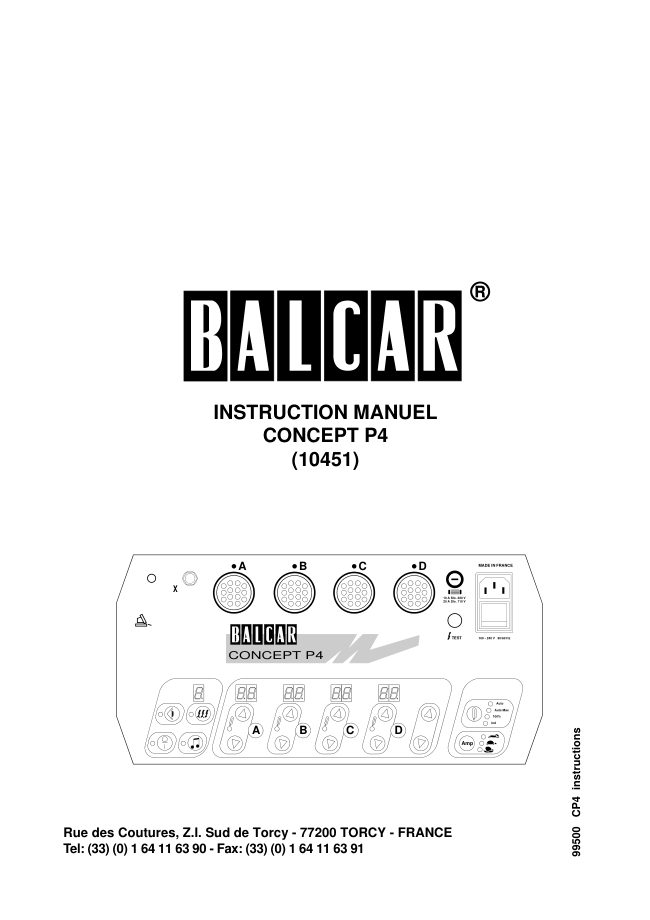
Balcar CONCEPT P4 User manual
User manual for Balcar CONCEPT P4. 8 pages in English. Read the original PDF, download or print a copy without registration.
8 pagesEnglish0.1 MB PDF
Loading your manual…Open PDF directly
Document details
- Brand
- Balcar
- Model / document
- Balcar CONCEPT P4
- Document type
- User manual
- Language
- English
- Pages
- 8
- File size
- 0.1 MB
- Category
- Film cameras
- Document date
- Not specified in catalog
Search available document text
Find a term, then jump to its page in the original PDF. Image-only pages may not be searchable; check the PDF for exact wording and diagrams.
Page 2 · Read text
1.  INTRODUCTION

Thank you for purchasing the latest in electronic flash technology. We hope you
will be satisfied with the high performance and versatility of your new CONCEPT
P4 unit. Please read the following information carefully before using your flash
unit.

The CONCEPT P4 must be used in conjunction with a BALCAR PS-U 3, PS-U 4
or PS-Z 4 light-head. Do not attempt to use the CONCEPT P4 with any other
light head. BALCAR U and Z heads are not compatible with the CONCEPT P4
system.

The power obtained in each head depends on the head model, the position of
the head power selector switch and the power setting on the CONCEPT P4.
Section 4. provides details on how to set power.

The CONCEPT P4 will function from 90 V to 260 V, 50/60 Hz. Voltage selection
is automatic.

Safety Warnings                                         Caution

    1.  THERE ARE ABSOLUTELY NO USER SERVICEABLE PARTS
        INSIDE THE CONCEPT P4. Never open the unit and never attempt to
          repair it. You might be injured by the high-voltage. BALCAR maintains
          repair stations around the world to give you the best service.

    2.  ALWAYS DISCHARGE and UNPLUG the light-heads before removing
         the Pyrex shell and touching the flashtube or the model lamp.

    3.  NEVER use fuses rated higher than those listed:

          CONCEPT P4     10 A slow-blow (used in 110 V)
                              20 A slow-blow (used in 220 V)

             PS-U/Z heads      6.3 A slow-blow

    4.  ALWAYS connect on the CONCEPT P4 on a properly grounded A/C
            line: this will reduce the risk of electric shock.

    5.  ALWAYS protect the CONCEPT P4 from excessive humidity, and
      NEVER use it under rain or on a wet floor.


     Weight                          5.2 Kg (11.5 lbs)

     Dimension                30x16x18 cm (12x6x7")

     Voltage spec                 90-260 V 50/60 Hz

    Max AMP draw
         w/out model lamp      6 A (100 V) to 2.5A (240 V)
         w/ 4 x 300 W lamps    20 A (100 V) to 7.5A (240 V)

    Max model lamp                 4 x 300 W

    Max nominal power        4 x 1,600 Ws (6,400 Ws)

    Power Variation range       4 f-stops + 2 on head


2                                                 CONCEPT P4 INSTRUCTION MANUAL
View original page 2Page 4 · Read text
3.  BEFORE YOUR START

Checking the head

Before using your CONCEPT P4 unit, you should check the proper condition of
your PS-U 3, PS-U 4 or PS-Z 4 head, by doing the following:

    1.   Remove the lamp protector

    2.   Remove the Pyrex protector shell

    3.   Using a clean cloth (not your bare fingers), make sure the flashtube is
         properly inserted into the flashtube sockets, and that it is resting on the
          trigger wire. Also check that the model lamp is screwed in tightly.

        Note:  touching the flashtube and model lamp with your fingers is                                                          Caution         harmful to the Quartz: the oil which you would spread on the lamps will
        cause it to heat and eventually burn out.

Connecting the head                     A

To connect the head to anyone of the 4 light head plugs (A,B,C or D):

    1.    Align the yellow dot on the plug with the yellow dot on the CONCEPT
        P4.

    2.   Gently insert the plug and rotate the locking ring clockwise until the
         plug is firmly locked into place (on new heads, this ring may be a bit
              stiff at first).                                                                    MADE IN FRANCE

Connecting the CONCEPT P4
                                                                                                                          10 A Slo. 220 V
You can now connect the CONCEPT P4 to a grounded A/C line, using the A/C        20 A Slo. 110 V
cord provided with your unit.

The CONCEPT P4 is powered by turning the ON/OFF switch of the A/C plug
assembly to the ON position. This switch is also called the "hardware on/off",
because it actually cuts off the A/C supply line when in the OFF position.                 TEST          100 - 240 V  50/60 Hz

The 0/1 switch at the bottom left of the control panel is called the "auxiliary
on/off". It is used to actually turn the unit on or off, after the hardware switch is
turned on.

When the hardware on/off is ON and the auxiliary on/off is OFF, the unit remains
powered, but in a wait state: the yellow LED will blink. If the O/1 button at the
bottom left was left off last time the unit was turned off, you will have to press it
to actually turn the unit on. If it was left on, the unit turns on immediately.

The CONCEPT P4 memorizes the position of each switch so next time you use
the unit it will be set the same way it was when you turned it off.


                                                                                                                                                   Auto Max4.  CHARGE RATE SELECTION
                                                                                                                                  100%
The CONCEPT P4 uses a high-frequency switch power supply to charge the                                       ind
capacitors. One of the benefits is a constant current draw during the charge.
                                                           AmpThis current draw is controlled using the Charge Rate Selector button, by press-
ing it until the desired charge rate is displayed.

4                                                 CONCEPT P4 INSTRUCTION MANUAL
View original page 4Page 5 · Read text
4.  POWER CONTROL
Head Sensing

The CONCEPT P4 senses the presence of a head connected to  it. In order to
turn a head on, the head must be connected to the unit. If the display of that
head does not turn on, the head on/off was left off last time that head was used:
just turn it on.

Note: the individual head double digit decimal display indicates whether the
head is on or off.

Decimal F-stops

The CONCEPT P4 power is displayed in DECIMAL f-stops. This system may
seem awkward at first, but it is actually quite simple.

         f-stop        power
         10             1/1            The individual displays                                                                         Individual Head Control           9.0             1/2                indicate the decimal
           8.0             1/4                f-stop of each head.
           7.0             1/8
           6.0            1/16


Power Control on the CONCEPT P4
Each key click corresponds to ± 1/10 f-stop, which is observable on a flash        A
meter (± the precision of the flash meter). Don't think in Ws, nor power percent-
ages, but rather in increase or decrease of f-stop.

For example, you wish to increase by 1/2 (5/10) f-stop a power setting of 8.2:
just click the up key 5 times (to 8.7).
                                                               Master Control
Power ratios between two heads are the difference between their displays. For
example, if Head A is at 8.0 and Head B is at 9.5, the power ratio is 1.5 (1 1/2) f-
stops, the difference between 9.5 and 8.0.

When using the Master Up or Down keys, notice that all displays increment or
decrement together, therefore preserving the light ratio between each head, as
the difference between the displays remains constant.

If any head reaches 10, the master up reaches its maximum.
If any head reaches 6.0, the master down reaches its minimum.

When power is lowered, you need to flash the unit (or the head) in order to
"dump" each head.
Power Control on the Head

PS-U/Z heads have their own power selector switch.  It is used to increase or
decrease the power range of your CONCEPT P4. For accurate model lamp
AUTO ratioing, each head should be at the same nominal power.

Maximum power on each head is obtained with the selector in the 1 position.
Numbers in () give the f-stop decrease from 1,600 Ws.

                  1             1/2 or 2/3           1/4 or 1/3
   PS-Z 4      1,600 Ws      1,066 Ws (-0.6)     533 Ws (-1.6)
   PS-U 4      1,600 Ws      800 Ws (-1.0)      400 Ws (-2.0)
   PS-U 3    800 Ws (-1.0)    400 Ws (- 2.0)      200 Ws (- 3.0)

CONCEPT P4 INSTRUCTION MANUAL                                                        5
View original page 5Page 6 · Read text
5.  MODEL LAMP CONTROL
Model Mode Selection
                                                           Model Mode Selection
The CONCEPT P4 offers many model lamp modes which are selected using the
Model Lamp Mode button at the upper right of the control panel keypad.

Each time you press the button, the model mode changes, and the correspond-
ing yellow LED indicator lights up. When no LED's are on, you have selected the                                   Auto
OFF mode.                                                                                                                            Auto Max
                                                                                                                           100%
    1.  OFF mode:                                                                                                                            ind
           All model lamps are turned off.

    2.   Ind (Independent) mode:
                                                       Amp       Each model lamp is lit at a specific level which you can modify. This is
         explained below.

    3.  100% mode:
           All model lamps are set at 100% (10) power, regardless of the flash
        power of each head.

    4.  AUTO mode:
       The model lamp level of each head is proportional to the actual flash
        power of that head. For example, a head set at 10 will have a model
        lamp level of 10 (100%). A head set at 8.0, will have a model lamp
          level of 8.0 (25%).

        True proportionality between flash and model lamp is only obtained  if
         the model lamp of each head is of the same type (i.e. all 150W or all
        300W), and if the power selector switch at the back of each head is in
        an equivalent position.

    5.  AUTO MAX mode:
         This mode is identical to the AUTO mode, but the intensity of the
        model lamp of the head at the highest flash power is set at 100%. In
         order to preserve proportionality, all other model lamp values are
         increased accordingly.

       The following example summarizes the differences between each
        mode:

       Head              A      B       C
        Flash Power             8.0        6.5         9.0
       Model Lamp Power                                               Individual Display & Control
         OFF            OFF     OFF      OFF
          100%              10       10        10
              ind.                  8.0*       8.0*         8.0*
         AUTO               8.0        6.5         9.0
         AUTO MAX          9.0        7.5        10

           * 8.0 is the default value, but you can change it to any value.
Model Mode Display/Independent Mode
By maintaining the Model Lamp Selector button pressed, the individual head       A
double-digit display will display the model lamp level for that head, until you
release the Model Lamp Selector. While still maintaining the Model Lamp
Selector button pressed, you can turn each model lamp on or off by pressing the
individual ON/OFF button of each head.

The individual model lamp yellow LED (to the immediate left of the individual
ON/OFF button) indicates whether that model lamp is on. Individual model
lamps cannot be turned on if the model lamp mode is OFF.


6                                                 CONCEPT P4 INSTRUCTION MANUAL
View original page 6Page 7 · Read text
In the Ind. (Independent) mode, the up and down arrows are used to raise or
lower the power of the model lamp independently from the power of the flash.
This can only be done  if the Ind. mode is selected. Note that the Model Lamp
Selector button must remain pressed long enough before using the individual
head controls.

                                                                               Cell           "X"
6.  SYNCHRO CONTROL
Synchro Hardware                                               X
The CONCEPT P4 is triggered using the TEST button/100% charge indicator,         10 A Slo. 220 V
the Synchro Jack "X" plug, the Photocell (if enabled) or the Sequencer.                  20 A Slo. 110 V

The unit will be allowed to trigger once it is 100% charged, and only if the TEST
button (or X sync contact) was previously released.

If there is a short-circuit in the synchro connection, the unit will not trigger again
(and the 100% indicator will not turn on), until the short is eliminated.                    TEST          100 - 240 V  50/60 Hz

A single head is triggered by pressing the TEST button at the back of that head.
If the photo cell is turned on, the other heads will likely also trigger. By maintain-
ing the head TEST button pressed, the individual head display will turn off: this is
                                                            Photo Cell/Beeper Conrolsuseful when you have lost track of what head is connected where.
Photo Cell

The photocell is activated by pressing the Photo Cell button. The yellow LED
indicator is on when the cell is active.

100% charge Audible Signal

The 100% charge audible signal is activated by pressing the audible signal but-
ton. The yellow LED indicator is on when the signal is active.

You can flash as soon as the audible signal starts.

Sequencer

The CONCEPT P4 Sequencer is used to create multiple flash sequences. It is
activated by pressing the Sequence Selector.  If activated, the decimal display                                                          Sequence Controland the yellow LED indicator turn on.

There are 2 sequence modes:

    1.   Count-down mode:

        Press the sequence button until the number of flashes you want is dis-
         played. Once the unit is triggered (using the TEST button, the "X" syn-
         chro plug or the photocell), the CONCEPT P4 will flash as many times
        as you requested as soon as it is at 100% charge. The display counts
       down until it reaches 0, then resets itself, ready for a new sequence.

       You can interrupt the sequence by pressing any key on the keyboard.

    2.   Count-up (AUTO) mode:

      When A is displayed, the unit will keep firing as long as you maintain
         the TEST button pressed, or the "X" synchro signal. The display counts
        up until you stop firing, then resets itself, ready for a new sequence.


CONCEPT P4 INSTRUCTION MANUAL                                                        7
View original page 7Page 8 · Read text
7.  MISCELLANEOUS INFORMATION
Misfiring

If a head misfires at lower power, you probably have a flash tube that is either
new or hard to trigger. Fire that tube at full power 50 times to "break  it in".  It
should fire correctly from now on.
Reset

To display additional CONCEPT P4 information, maintain the O/1 Auxiliary
ON/OFF button pressed until C O N C E P T P 4 is displayed.

The software version number will then be displayed following the U. display:

If you maintain the ON/OFF button pressed, the unit is reset to its original factory
configuration.

The number of flashes made is then displayed. If you maintain the ON/OFF but-
ton pressed, the display will zero itself (wait until the 0's appear).
                                                                                  MADE I
Changing the Fuse

Turn the unit off and unplug the A/C cord if you need to change the fuse on your
CONCEPT P4.

                                                                                                                    10 A Slo. 220 V
Unscrew the fuse holder using a flat-blade screwdriver. Replace the fuse with                    20 A Slo. 110 V
the same rated fuse.
Flash Duration and Color Temperature

As a general rule, raising and lowering power using the variators will not affect
flash duration but will modify color temperature. On the other hand, using the
power selector at the back of the head will change flash duration while maintain-
ing color temperature.

For shorter flash duration, set the head at the lowest power setting using the
head power selector. We recommend adding a second flash tube (in the "cross"
position), which reduces flash duration up to 40%.

For optimal color temperature, use clear shells when lighting with diffusing
accessories, and yellow shells with direct reflectors.
Travel Recommendations                                                          Caution
When going on location make sure the CONCEPT P4 and the heads are proper-
ly packed. Take special care in guarding against shocks and in protecting the
glass (flashtube, model lamp, Pyrex shell) of the head. If necessary, remove the
glass and protect it separately.

Always carry a spare synchro cord and spare glass.


We hope you wil enjoy the use of your new CONCEPT P4, and we thank you
again for your purchase.

Please mail or fax any comments to:                                                                                                                                                                                                                                                                                                                                                                                                                   instructions
      BALCAR S.A.
       Rue des Coutures, Z.I. Sud de Torcy                                                                                                     CP4
       77200 Torcy FRANCE
            tel: (33)(0) 1 64 11 63 90 - fax: (33)(0) 1 64 11 63 91
         e-mail : sales@balcar.fr - http://www.balcar.fr                                                                                                                                                                        99500

8                                                 CONCEPT P4 INSTRUCTION MANUAL
View original page 8From the M. Butkus archive. Original publisher and archive notices are retained.
Check the model and edition against your equipment.
PDF verified 2026-10-10.