Film cameras
Balda Super Baldina via translation User manual
User manual for Balda Super Baldina via translation. 15 pages in English. Read the original PDF, download or print a copy without registration.
15 pagesEnglish6.7 MB PDF
Loading your manual…Open PDF directly
Document details
- Brand
- Balda
- Model / document
- Balda Super Baldina via translation
- Document type
- User manual
- Language
- English
- Pages
- 15
- File size
- 6.7 MB
- Category
- Film cameras
- Document date
- Not specified in catalog
Search available document text
Find a term, then jump to its page in the original PDF. Image-only pages may not be searchable; check the PDF for exact wording and diagrams.
Page 1 · Read text
www.butkus.us

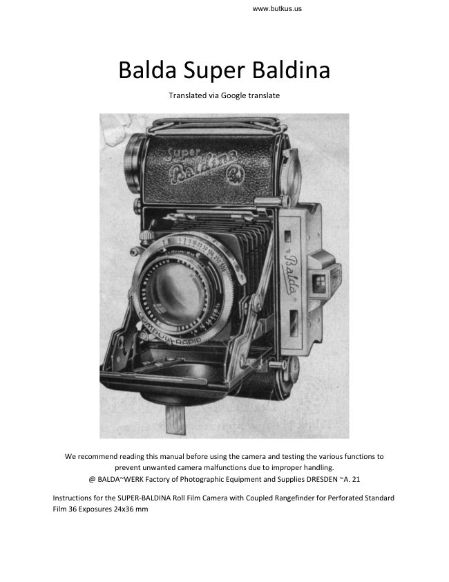
     Balda Super Baldina
                               Translated via Google translate


  We recommend reading this manual before using the camera and testing the various functions to
                 prevent unwanted camera malfunctions due to improper handling.
     @ BALDA~WERK Factory of Photographic Equipment and Supplies DRESDEN ~A. 21

Instructions for the SUPER-BALDINA Roll Film Camera with Coupled Rangefinder for Perforated Standard
Film 36 Exposures 24x36 mm
View original page 1Page 4 · Read text
Fig. 2
M. Rear cover lock
O. Telescope viewfinder
P. Rangefinder aperture
R. Upper film spool (non-removable)
S. Film transport roller, Film pressure spring
U. Film pressure plate
T. Film guides


Negative material to be used: Daylight cartridges with perforated 35 mm standard film for 36 exposures
(24 x 36 mm), or meter film of any length. You can use a rewinder or have the film loaded by a camera
dealer. It is recommended that you first purchase a daylight cartridge with 36-exposure 24 x 36 mm
standard film. If you give the film to a camera dealer for development, have the cartridge returned, as it
can be reused. The camera dealer simply needs to load a new film.
View original page 4
Page 6 · Read text
www.butkus.us


Loading the Film:
The camera back is opened by sliding the locking latch M sideways under the carrying handle. The back,
which is firmly hinged, is folded back. Now pull the rewind key H outward and insert the film cartridge
into the lower film holder. Make sure that the (matte) side of the film is facing the lens. The hollow side
of the cartridge is thus on the side of the rewind key, which is now pushed back with a slight turn. The
end of the film protruding from the daylight cartridge is threaded into the upper, non-removable take-
up spool. It is sufficient to push the end, which has been cut on one side, under the tongue incorporated
in the spool core, whereby the film rests against the edge of the spool and the teeth of the transport
roller engage in the perforation of the film, as shown in Figure 4.
View original page 6
Page 7 · Read text
By turning the film winding wheel clockwise, the film is wound up until it lies taut on the frame, whereby
the teeth of the transport roller must engage the perforations in the film. The back is now closed. Move
the film into the exposure position: The film advance release mechanism with safety slide: The film
winding wheel is locked as soon as it is wound up for a shot.


This prevents accidental rotation of the film wheel and simultaneously ensures regular winding. The
release mechanism consists of a release button, which is locked by a safety slide. After the film winding
wheel has been turned to the stop, the safety slide is pushed up, which allows the release button to be
pressed in. The film wheel is then turned further until it locks again.
View original page 7
Page 8 · Read text
www.butkus.us


Since the exposed portion of film is unusable, it is rewound by turning the film wheel twice in
succession, as described below. A sure sign that the film is being wound correctly is the rewind key
turning each time. Get into the habit of advancing the film immediately after taking the picture, as this
avoids double exposures of the same section of film. The camera is then always ready for the next shot.


Please note: The flatness and precise focus of the film during exposure is guaranteed by the film guides,
the double-sided pinion, the double-sided pressure spring, and the film pressure plate. The play of the
film cassette in the lower film chamber has absolutely no influence on the film's focus.

Film counter with protective cover By turning the film winding wheel, the film counter automatically
advances by one mark with each shot. After loading the camera as described above, set the film counter
pointer to the first mark – i.e., image number 1.
View original page 8
Page 9 · Read text
Taking the Photo Opening the Camera: By pressing button K, located below the counter, the camera
pops up and is set to "infinity" - the spreaders are securely and firmly locked.

Setting: For long-distance shots over approximately 15 m, the helical gear setting remains at "infinity"
(oo).


For shots under approximately 15 m, the camera is adjusted using the coupled rangefinder. Take the
camera in both hands and bring it very close to your eye with the rangefinder's viewing aperture, while
placing your index finger on the worm gear knob. (See Fig. 8.) Looking through the camera, you will
notice a section of the image that is horizontally divided into two halves. The upper half contains an
inverted rear sight. The lower half is colored yellow. When adjusting the worm gear lever, C, the upper
View original page 9
Page 10 · Read text
www.butkus.us


half of the image shifts sideways. Aim at the object to be adjusted using the rear sight and adjust the
lever until the vertical lines align with the image.

The camera is then focused on the desired object. The distance can be read from the scale.


The rangefinder's large and bright field of view allows for effortless and rapid focusing even of dark or
poorly lit objects, and can therefore also be used as a viewfinder. The helical gear knob is designed so
that the camera can only be closed when the helical gear is set back to "infinity." Image Searching The
telescope viewfinder is located diagonally above the rangefinder's viewing aperture. It’s clear and
precisely defined field of view enables precise and rapid searching. Parallax, which becomes noticeable
in close-up shots, is automatically compensated. By coupling the viewfinder to the helical gear, the
viewfinder image matches the image in its boundaries at any set distance. The viewfinder is tilted
simultaneously with the focus adjustment so that its optical axis is brought more or less close to that of
the lens at different settings. This parallaxes difference between the lens and viewfinder is practically
eliminated. Parallax-free image search is especially important for close-ups. The unpleasant image shifts
or images with "cut-off heads" are eliminated with this viewfinder because you can rely on what you see
in the viewfinder being the exact boundaries of the image as it appears on film.
View original page 10
Page 11 · Read text
Depth of field by Aperture and in meters

Depth of Field:
The aperture is set in the usual way by sliding the pointer to the desired aperture. To check the greater
depth of field achieved by stopping down, a depth of field table is located on the back of the camera.
The meter numbers in the "Set Distance" column indicate, horizontally, the range within which sufficient
sharpness for good magnification lies. If, for example, in a close-up shot, all objects from 2 m to 3.50 m
are to be sharply depicted, it is easy to see from this table that stopping down to f/5.6 is required and
the scale pointer must point to 2.5 m. Since the limited size of the depth-of-field table makes it
impossible to specify every possible distance and lens aperture (aperture), it is nevertheless easy to
determine any set distance or aperture that lies between the given numbers by taking the nearest value
and increasing or decreasing it accordingly. Any small difference that may arise is practically ineffective.
View original page 11
Page 12 · Read text
www.butkus.us


Snapshots:
Set the shutter to the appropriate exposure time and aperture, preferably using an exposure table or a
light meter. Instructions for the shutter are included separately. After setting the camera correctly,
check the image to be taken in the viewfinder again and release the shutter using the shutter release
button G. For snapshots, the shutter must first be cocked. Important! When cocking the shutter, note
the following: At the fast instantaneous speeds, considerable pressure must be applied to cock the
shutter. If the lever is cocked with only one finger, the lens mount can easily be compressed, which can
then detrimentally affect the focusing. Therefore, counter pressure must be exerted when cocking by
cocking with the thumb and supporting the bolt with the other fingers, as shown in the following
illustration.
View original page 12
Page 13 · Read text
Time-lapse photography is primarily suitable for flash photography, indoor photography, and night
photography. It's best to mount the camera on a tripod or place it on a solid support (table, chair, fence,
etc.).

Set the shutter to the mark B or T. In this case, the shutter must not be cocked. (See enclosed shutter
instructions.) A cable release, which is screwed into the nipple on the shutter, can also be used.

Finger pressure.
Shutter release on the body Fig. 12 The shutter on this camera is released by the push button located on
the body next to the counter (see above illustration). The camera is held firmly in both hands during
shooting, with only the free index finger pressing the push button. This secure position largely prevents
camera shake and vibration during shooting.
View original page 13
Page 14 · Read text
www.butkus.us


Closing the camera:
Always ensure that the screw thread is set back to "infinity" ( oo). Then hold the camera in both hands
and release the spreader guide by applying even pressure with both thumbs on the upper arms. This will
move the lens back into the body (see Fig. 14). Then close the cover completely.


Rewinding the film:
When the 36th mark appears on the counter, 36 exposures have been reached. But you can safely try
whether the film winding wheel can be turned all the way again, and if so, take another exposure. Then
the film must be rewound into the cartridge, since the upper film spool cannot be removed from the
camera. By pulling out the winding wheel, the mechanical lock is released, switched off, and the
rewinding is released. Now hold the camera in your left hand and turn it upwards with your right hand,
folding the handle to the right until the film is rewound into the cartridge. ~ While rewinding the film,
the counter also rotates back, so that the position of the rewound film can be seen at any time. After
number 0 appears on the dial, turn back 2-3 more times - then you'll notice that the rewinder turns
quite easily. Now the exposed film is back in the daylight cartridge, and this can now be replaced in
daylight, but it must be protected from direct sunlight.

As an important accessory, the color filters are essential for certain shooting purposes.
Furthermore, there are also conversion lenses for close-ups. The SUPER-BALDINA allows
shots from a distance of up to 0.85 m. For closer subjects, a conversion lens is required. For the
View original page 14
Page 15 · Read text
Trioplan, Xenar, and Xenon, an original conversion lens, designed for the respective lens, is
supplied. An original conversion lens is included that is matched to the respective lens. These
focusing lenses allow for close-up shots of approximately 50 cm to 1 m. A Zeiss Proxar lens is
used for the Tessar, which allows for close-up shots of approximately 50 cm.
View original page 15
Related documents and language editions
From the M. Butkus archive. Original publisher and archive notices are retained.
Check the model and edition against your equipment.
PDF verified 2026-10-10.