Film cameras
Beattie Universal Studio camera User manual
User manual for Beattie Universal Studio camera. 23 pages in English. Read the original PDF, download or print a copy without registration.
23 pagesEnglish5.7 MB PDF
Loading your manual…Open PDF directly
Document details
- Brand
- Universal
- Model / document
- Beattie Universal Studio camera
- Document type
- User manual
- Language
- English
- Pages
- 23
- File size
- 5.7 MB
- Category
- Film cameras
- Document date
- Not specified in catalog
Search available document text
Find a term, then jump to its page in the original PDF. Image-only pages may not be searchable; check the PDF for exact wording and diagrams.
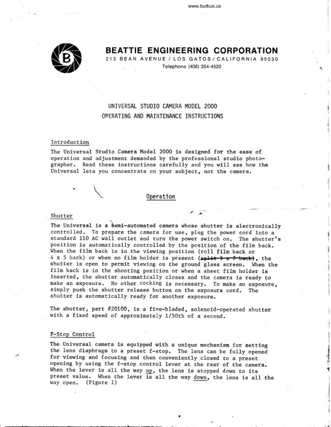
Page 1 · Read text
www.butkus.us


          BEATTIE ENGINEERING CORPORATION
               213 BEAN AVENUE / LOS GI\TOS/CALIFORNIA 95030
                                          Telephone (408) 354-4520$


                  UNIVERSAL STUDIO CAMERA MODEL 2OOO
                OPERATING AND MAINTENANCE INSTRUCTIONS


Introduction
The Universal Studio Camera Model 2000 Ls desJ.gned for the ease of
operation and adJustment demanded by the profeissional studio photo-
grapher. Read these instructions carefully  arrd you will  see how the
Universal lets you concentrate on your subject, not the camera.


                               0peration


                                                                                                                                                                                                                       --
                                                                                                                    "Pt''Shutter                                                                        {
The Universal is a lernt-automated camera whose shutter is electronically
controlled.  To prepare the camera for use, plug the pov/er cord into a
standard 110 AC wall outlet and turn the power switch or1. The shutterts
position is automatically controlled by the position of the film back.
Wtren the film back is  in the viewing position (ro11 filn  back or
4x5back)orwhennofi1mho1derispresent(ffi,the
shutter is open to permit viewing on the ground glass screen.  Wtren the
film back is  in the shooting posiEion or rirhen a sheet filn  holder is
inserted, the shutter automatically closes and the eamera is ready to
make an exposure. No other cocking is necessary. To make an exposure,
simply push the shutter release button on the exposure cord.  The
shutter is automatically ready for another exposure.
The shutter, part #20L00, is a flrre-bladed, solenoid-operated shutter
with a fixed speed of approximately 1/5Ottr of a second.
                                                                                                                                                                                                                                                                                                                                                                                                                                     i
F-Stop Control                                                                                                                                                                                                                                                                  1
The Universal camera is equipped with a unique mechanism for  settl-ng                                                                                                           {j
                                                                                                                                                                       Ithe lens diaphragm to a preset f-stop.  The lens can be ful1y opened                                                     .'d
                                                                                                                                                                                                             afor viewing and focusing and then conveniently closed to a preset
opening by using the f-stop control lever at the rear of the camera.
I'ltren the lever is  all  the way up, the lens is stopped down to its                              {
preset value.  I,Jhen the lever ls  all  the way down, the lens is  all  thelsay open.  (Figure 1)
View original page 1Page 2 · Read text
f-stop contnol
                                                                   lever    To Set the F-Stop
    To change the preset value
    of the f-stop control, move
    the f-stop lever toward the
    rear of the camerar apply-
    ing pressure at the end of
    the lever nearest the camera
    body. Wtren the f-stop dial has
    disengaged from the pin, push
    the lever up or down to arrive                                    pln
    at the desired setti-ng.
    Note: Black figures should be                     f-stop adjusting
    used wlth f4.5 or f5.6 lenses.                            scnew
    Red figures should be used
     for f6.3 lenses.
                                                  Figure 1


Focusine
The camera is focused by knobs located on each side of the camera body
 (rigure  2) .  Table 1 shows maxirnum and minimum focusing distances for
standard lenses. To focus the camera, pLace the film back in the view-
ing position and rotate the focusing knobs until  the image on the ground
glass is sharp. To l-ock the focusing position,  rotate the knurl-ed
focus lbck knob clockwise until   it  is  tight.   To release, simply reverse.

Interchangeable Film Backs                                                             ,                     :
The Universal Studio Camera is designed to accept a wide range of film
backs for varying fllm formats.  These backs are easily lnterchanged.
For more information on available film backs, contact your Universal
dealer.  A11 film backs are mounted on revolvl-ng backs. The split  5 x 7
back (1t20825) and the ro11 film back (//20800) are mounred on revolvlng
back 1120300-L. The 4 x 5 back (#20350) is mounted on revolving back
1120300-2.
Film backs al-l sl-ide from side to side of the revolving back. The
sliding travel of the film backs is controlled by the film back retainlng
bracket. To slide the back frcrn one position to the other, pul1 down
on the locking pin and push it  to the desired direction.  To urinimize
the possibility of moving the camera during the sliding operation,
slide the back as follows: After the back has been moved slightly,
squeeze the locking pin and the fJ-ange on the retaining bracket in
the direction of travel together with the thumb and index flnger untilthe locking Pin is engaged in the slot on the retaining bracket.
View original page 2Page 5 · Read text
Changing the Filn Backs
                                                                       theTo change the filn  backs, locate the back Ln use approxlmately in
center of the revolving back. Pu1l the retaining bracket downward at
Tab rrgrr and move lt  toward the front of the caoera. Sl-Lde the ftln                                                 new back toback off the revolving back to the rlght.   Install the                                                    same time pullthe approxlmate center of the revolving back and at the
the folgng pln down and return the retaLnLng bracket to lts orlginaL
posltion.

Revolving Back
A11 ft]-n backs may be rotated to any posltLon by rotatLng the revolvlng
back. To rotate, loosen the locklng knob, move the revolvlng back to
the desired posltion, and retLghten the locklng knob.

Removlng the Revol-vlng B?ck
To remove the revolving back frm the caoere, fltst  dlaconnect the Plug
at the bottom of the bracket. Then, looeen the loeklng knob and rotate
the revoLvlng back untll  tt  ls exactlv upslde down, and gently Llft   lt
off.  To lnstall or replace, reverse the above procedure.

Changlng Lenses
To remove the Lens from the camera, disconnect the sllde lock on the
f-stop control llnkage (Flgure 3).  Unscrew the trro knurled thumb screwB
at top and bottom of the lens plate, and remove the lens. To lnstaLL
the lens, reverse the procedure.


                     tilting  back
                 locking knob

                                                             shutten
                                                             thumb
                                                             scnews

        slibe
        Lock


            shutten         www.butkus.us
            electnical
            Plug                              Figune 3
View original page 5Page 6 · Read text
www.butkus.us


              Tilting  Back (Optional)
          The tilting  back is designed to provide depth of field  control when
            photographing groups or a seated subject.  To operate the tilting   back,
           loosen the knob on the top of the camera, tilt   the back to the desired
             position, and retighten the knob.  trrlhen using heavy electric  magazines,
           care should be taken to support the mag azine and back with one hand whil-e           making this adjustment.

          Use of Strobe Lights
           The Universal Studio Camera automatically synchronizes the firlng  of
             electric  strobe studlo lights when the shutter is released.. A plug for
           the light  is located in the electrical  unit on the side opposite the
           power switch. A mating connector for the plug is furnLshed with the             camera.

          Use of Electric Magazines
          The Universal may be used with many types of electric  long roll  maga-
            zines.  The magazines can be used with either the ro11 filn  back or the
         4 x 5 back, depending on the manufacturer. The Beattie Engineering
           magazine is designed to  fit  the 4 x 5 back.  For further  information, [\,        contact your local dealer.  Use of magazines with the above-mentioned
                                                                                                                                                              --!:-          backs is described in the section covering eaeh film back. A plug is {          furnished on the back of the electrical  control unit  for connecting the
          magazine. Different plugs are used by various manufacturers on their
          magazines.  If  the plug on your magazine does not  fit  the Universal,  v'{           write to Beattie Engineering corp. giving the manufacturer, model number
          and serial number of the mag azLne. ltte    supply an adapter cable at         a small cost.                               "in
           InportanF: The shutter release on the universal is not electrically
           interlocked to the drive motor of magazines not manufactured by Beattie          Engineering. To insure proper operation, the shutter release button
           should be depressed when taking a picture until  the mag azine drive motor          engages. This takes between L/z and 1 second.

             Rol-l Filn Back
          The ro11 film back, part #20800, is  for use wLth Graflex Series 23
           120-220 filn  holders, and for certain 35urm, 46uur, and 70mrn long rorl            electric  magazines. wtren the ro11 film back is  in the right-hand po-
            sition on the revolving back, the camera is  in the taking mode and. press-           ing the shutter release button actuates the shtrtter.   In the left-hand            position,  the shutter automatical-ly opens for rriewing.

               Graflex Adaprer plate
              Graflex Series 23 ro11 film holders RH_g, RH-10, RH-12, and RH-20
              can be used with the ro11 film back. The Graflex adapter plate
View original page 6Page 7 · Read text
thesewhlch is supplied wlth the rolL filn  back must be used with
film holders. To assemble the filur holder and the adapterr Po-
sition the adapter as shown in Figure 4.  Be sure that the trTtt                                    open magazlne. Insert fllnis at the top.  Remove dark slide and
plate into adapter and cl-ose magazine.


                                                                   lfTfl'


                             Gnaflex adapten plate


                                                Grafl-ex      magazine


      Figune 4


Electtlc Megazlnes
When using one of the Large electric magazines, check to see that
 the ro11 filn back does not pull away fron the surface of the re-
vol-vlng back, thus ereating a llght leak.   If  this does occur,
remove the leaf spring from the top of the ro11 ftln back and in-
crease the bend.
View original page 7Page 8 · Read text
www.butkus.us


Split5xTFilmBack                                                                                                                                                                                                                                                                                                                                                                                                                                                   :                                                           ,
The split  5 x 7 back, part t120825, uses standard 5 x 7 cut film  holders.
To insert 5 x 7 film holder into  spl:'-t 5 x 7 back, depress handle at the
 left  of the back.  This will  raise the ground glass and allow the filn
holder to slide  into place easily.  Be sure that the film holder is  in-
serted fu1ly before maki:eg exposure. The locking rib on the film holder
should fit  the groove on the split  5 x 7 back. To check this,  without
depressing handle, try  to pul1 film holder out of lock.    If you are
unable to pul1 out the film holder in this manner,  it  is  in  its  proper
position.
I,{hen the fil-'holder  is inserted, the shutter should close.  tr{hen tt  ls
removed, the shutter should open. I'  the shutter does not open but works
properly with other fihn backs, loosen the actuauing bar ret*ining screT{
with the supplied Allen vrrench.

4x5FilmBack
The 4 x 5 back, part /120850, accepts standard 4 x 5 cut film holders and
many "Graflok type" magazj-nes up to and including 90nn ro11 film.     trrlhen
the 4 x 5 back is  in the right-hand position on the revolving back, the
camera is  in the taking mode and pressing the shutter release button
actuates the shutter.   In the left-hand position,  the shutter automati-
cally opens for viewing.
When using standard 4 x 5 cut fiLrn holders, attach the cut film  plate.
Insert the holder fron the top.  The film back is  light  tight  and can
be moved from the viewing position to the taking position and vice versa
without fogging the fllm.

    Electric Magazines
    hrhen using ro11  f ikn magazines, remove the cut  f ilm p1-ate by un-    screwing the two reEaining screws. Place |tGraflok typett magazine
   on film back and slide locking bars down
                   ''    Masks


                                                                                                                                                                                                                                                                                                                                                                                                                                                                                                                                                                                                                                                                          '    Filn  forrnats of less than 4 x 5 requlre masking the ground glass.
   Two masks are supplied with the back--one for 2 L/4 x Z 3/4 format
   and one blank.  The optical  axisr or center of the mask, is marked
   on the blanl'- mask by a small hole, and a razor blade or a sharp
    knife can be used tc cut the mask for any desired ftlm format.
   The mask is inserted through a slot and should slide under the ground    glass retaining  c1Lps.
View original page 8Page 9 · Read text
Adjustment and |t'|iiintenance Procedures

  The Universal Studlo Camera requires no routine mal-ntenance. In addition,
  all adjustments have been made at the factory and should require no atten-
  tion.  Should a problem occur, the camera is designed to make repair a
  simple matter. The  f ollo'wing paragraphs describe maintenance procedures
  and adjustment for the c€unera. If the c€rmera cannot be repaired by
  following these procedures,  it  shoul-d be returned to BeattLe Engineering.
                                                             i   "'  The Shutter                                                                                       4
  The shutter assembly is affixed  to the camera by two thtnnb screrf,s
  (Figure 3).  To remove the shutter,  first  disconnect the slide lock on
  the lens f-stop control lLnkage and unplug the shutter electrical cable.
  Then remove the two thr.rmb screws.
  The operation of the shutter Ls
  relatively  simple and should
  cause no problems. However,  if
  adjustments are required, re-
  move the shutter from the camera.
   It  operates as follows:   WLren                            Figure                                               solenoid                     5
  taking a picture,  the solenold               screws  is actlvated and the shutter
  blades are opened. This move-
  ment trips a switch which fires
  the electric  flash units and
  advances the film  in electric
  magazines. This switch is
  audible (when the shutter is
  removed from the camera) and
  should "clicktt when the shutter
  blades are about l/8-inch  from
  being completely open.  If  this
  is not the case, loosen the two
  screws holding the switch and
  adjust as required (Figure 5).
   If  the shutter blades do not               switch                                                 "r  close fully  or close so far                screws  that there is a light  leak, dd-
  just  the blade travel adjusting
  screw.                                             blade travel
                                                       adjusting scnew
Note r Thls camera ls equlpped wlth a new f-stop controlthat allows settlngs ln-between normar f-stops.
To set the value of the f-stop eontrol, unscrew the f-stopcontrol lever sllghtly.  Now pull the f-stop lever toward.the rear of the camerar applylng pressrlre at the en4 of thelever nearest the cemera body. Push the lever up or d.ownto arrlve at the deslred settlngs. At full  stops a pln wlllengage .  Now TfGHTEtg TttE  , E-Sftlp COnfnOl     . For hal f  s tops  ,tlghienlng th                          hlch malntalns thesettlng.  so make sure lt  ls properry tlshtened.
View original page 9Page 10 · Read text
www.butkus.us


           The Electrlcal SYstem
           Ihe electrical control unit is mounted on the bottom of the camera. It
              incl-udes the electronlc clrcuitry necessary to operate the shutter,
             fires strobe 11ghts tf used, and advances the fllE  ln electric magazines
                    if used. A11 cords are connected to the control unLt. These are:
                1.  The AC power cable nh ich plugs Lnto any standard wal1 outlet.
                2.  The shutte: cable whlch plugs lnto the front of the shutter board.
                3.  The rerolving back cable whlch plugs lnto the botton of the
                    .     revolving back.
                4.  The shutter release cable whlch the photographet uses to operate
                   the shutter.
            In addltlon, the electrl.cal control unLt has an on/off swltch and a
             pilot  light.
            In case of electrlcal problerns:
                1.  Cheek to be sure that all plugs are prope"ly connected'        (the rrall
                   plug, shutter plug, and revolvLng back plug), and that the on/off
                        sr'ltch ls in the "on[ posltlon.   If a problen still  exists:
                2.  Unplug the AC wall cord and ?emove the electrlcal control unit
                 as follows:
             ,,---€--     a.  Unplug the shutter cable and the levolving back cable.|..EFF-                       b.  Turn the focuslng knobs untll the bellows and lens board                             .                          are retracted into the camera as far as they will  go.
                         c.  Unfasten the four screws hol-dl.ng the electrical control-
                            unlt and renove the unit, taklng care to feed the shutter
                           cable through the hole ln the bottotrl of the canera hood.
                 3.  Check the cables and terminals within the unit  for loose connec-
                      tions.    If  there are none, the electrical  unit must be replaced.

            Shutter Programing Switch
           The revolving back contains the switch that senses whether the shutter
            should be open for viewing or closed for taking (Figure 6).  With the
            camera plugged in and no ftlm back lnstalled,  the shutter should be open.
            Depressing the switch actuating ro1ler should cause the shutter to close.
                    If  the shutter does not open and close properly when using a film
            back, remove the film back and check to see that the swltch roller  can
           move freely.  The roller  shoul-d protrude above the surface about
            9/64-inch and should "click"  when it  is protruding about 1/16-inch.
                    If  this  is not the caser loosen the adjusting screws and adjust as
             required.
View original page 10Page 16 · Read text
www.butkus.us


 UNIVERSAL BECAUSE
                  It provides for both cut and roll film.
                 lt will accept lenses with focal lengths between 6" and 12"
                    It does all studio jobs including copids.

 DESIGN FEATURES
       The camera combines easily interchanged, standard single
           lenses, an electric shutter and a rack over or sliding back. All
           controls are at the back or side of the camera including an t/
         stop pre-selector. The camera provides semi automatic opera-
            tion for cut film and automatic operation for roll film magazines.
           Different film backs are interchanged in seconds.
 CUT FILM OPERATION
         The shutter closes automatically when the film holder is inserted
        and is set for immediate exposure. The shutter opens for view-
           ing when the film holder is removed.

 ROLL FILM OPERATION
         The shutter opens automatically when the ground glass viewing
          panel is moved in front of the lens. The shutter closes and is
          ready for exposure when the film is racked into place.

 FEATURES
     o Hooded image viewing in normal light without dark cloth
     o Pre-set f Z stop control
     o Revolving back locks at any angle
      o Automatic shutter opening for viewing
     o Focusing lock
     o Unitized electrical system
      o Accepts color roll 120-220 with Graflex magazine
      o Accepts standard  roll film maoazines-3s, 46 & 70 mm

  SPECIFICATIONS
          115 Volts A.C. 50-60 cycles.      Weight 15 pounds approx.

  UNIVERSAL STUDIO CAMERA

          TRTCX Photo$raphic Inc"
                   1919 S. E. BELMOITT STREET
                  PORTI.AND, OBEGOH g|2I*
                    29.9272 - P.0. BCtl( l$to

  BEATTIE ENGINEERING CORPORATION
   213 BEAN AVENUE / LOS GATOS / CALIFORNIA 95030
                          Telephone (408) 354-4520
Printed in U.S.A. 68"2                                              Design subiect to change without notice'
View original page 16Page 17 · Read text
PORTRAFLEX
                        studio/senior
                     portrait camera


  All conlrols al lhe                                SINGLE LENS REFLEX DESIGN
rear of the cam€ra,                                       Lets you look through the taking lens. No parallax
  including pre-set                                             distortion with any lens or subject distanee.      f-stop control

                                           HEMISPHERIC VIEWING SYSTEM
                                                  The viewing hood rotates 360 degrees to allow viewing
                                                   from rear, side, or front of the camera. The viewing
                                              hood also'tilts so you can view easily, regardless of
                                                 camera height.

EASV OPERATION                                     FLEXIBILITY
One lever programs the shutter, controls the reflex    Single lens design means easy and economic inter-
mirror and sets the f-stop. Pushing the shutter release     changeability. Both sharp or solt focus portrait lenses
button exposes the film, advances the electric mag-     available. Standard 4 x 5 Graflok back accepts many
azine and triggers the electronic flash.                   popular film holders.


    BEATTIE ENGINEERING CORPORATION
       213 Bean Avenue r Los Gatos, California 95030 . Phone: (408) 354-4520

     Printed in U.S.A. 70-1                                             Prices aM design subject to change without notice.
View original page 17Page 22 · Read text
www.butkus.us
                             n,                             (u'I',!        ffi
          Photogenic llachine trompany
                                Beattie Engineering Division


                    TNSTRU CTTON S

           VTGNETTER, CATALOG NO. AJO1


ASSETtsLY TNSTRUCTTONS:
                                                                                                                                                          i
1.  Attach frame to support assembly with screwr spring    washer, and flat  washer. Be sure that the small    square rod i s pointing forward as shown in diagram.
2.  Connect the horizontal control linkage to the    square rod on the frame assembly with t!t"  small
    retaining ring.  The pin of the vertical  control    linkage Etrould be in the slot of the frame assembly.
).    ff your camera is not drilled f9q !b" -Yignettel,-use                                                         hole s.     temft-ate provided to drill  two l/t6i  diameter                                          camera up-    Cut out template-     on dotted lines.  Turn                                                  rubber    side d.own.  Lo cate template again st edge of                                                      edges    molding so that edges of template line 9p 1+th                                                       two    of the c&fler&o Mark hole location and drill    17t|"-Oiameter ho1es.. (Holes can be as large as t/tn"    diameter if  desired.)
                       camera with two thumb screws.4.  Attach vignetter to
OPERATTNG TNSTRUCTTONS :
In-ser! the vignette-r-in the- frame--assendfly-. In addi*                                                                              ction to the pie-cut vignett ers, extra .sheet s 9l plasti                                                      The. vig-are supplied- so you can cut your own shape.                                                                                                                     .netter-is  controited by the two knobs which can be oper-                                                      ver-                                         assembly- in                                                                       .aated independently to move the frame                                                       beiicat  or lrori zont-aL direction.  The rod can alsomoved forward and backward. to adiust the di stance be-
tween the lens and the vignetter.

                                                                      I

                                                                         N
                                                  {
                                                                                                                       i
 (tzz-gzo54i)
View original page 22From the M. Butkus archive. Original publisher and archive notices are retained.
Check the model and edition against your equipment.
PDF verified 2026-10-10.