Film cameras
Bell & Howell Bell and Howell Foton User manual
User manual for Bell & Howell Bell and Howell Foton. 49 pages in English. Read the original PDF, download or print a copy without registration.
49 pagesEnglish28.2 MB PDF
Loading your manual…Open PDF directly
Document details
- Brand
- Bell & Howell
- Model / document
- Bell & Howell Bell and Howell Foton
- Document type
- User manual
- Language
- English
- Pages
- 49
- File size
- 28.2 MB
- Category
- Film cameras
- Document date
- Not specified in catalog
Search available document text
Find a term, then jump to its page in the original PDF. Image-only pages may not be searchable; check the PDF for exact wording and diagrams.
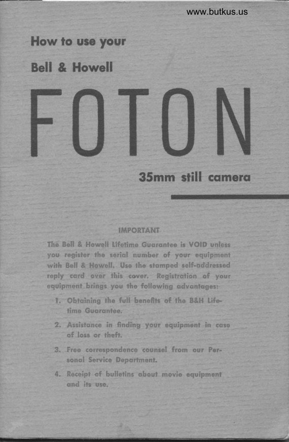
Page 1 · Read text
www.butkus.us

How lo use your
Bell & Howell
     NFOTO
           35mm still csmers


                    IMPORTANT
    The Bell & Howell Lifeiirne Gusrqniee ir VOID unlem
    you register the seriqt number of your equiprnent
    with Bell & Howell. Use the slomped telf-addresrod
      reply_ 'cerd over this cqver. Regirtrution of your
    equipment brings you the following odvontoges:
         l.  Obrcining the full henefttr of rhe B&H Life.
          lime Guqrqnlee.
      2" Aelisrsnce in finding your equipment in cqss
          of lors or lheft-
      3. Free correspondenco  countel from our Per.
         ronel Service Deporfmenf.
     4. Receipf cf bullerins qboul movie aquipment
        ond ils use.
View original page 1Page 3 · Read text
www.butkus.us
G"***ono!
  You havc purchased thc finest 35rnnr still canrera
 owned by anyone, anywhere. And with it, a Bell &
 Howell promise of professional "stills" with amateur
 ease throughout its long life.
   Behind this promise and your Foton stand ten years          I+
 of painstaking research, the tireless workmanship of
 engineers and master craftsmen, and the finest ma-
 terials in the more than 500 parts that compose
1,our precision-built instrument.
  Pride in your purchase   in its far-sighted func-tion:rl design; its nerv T-calibrated-           lens; its wear-
resistant finish; its attractive styling   will growwith the years. Confidence in your investment-                is
justified by the knowledge that your Foton is guaran-
teed for life    during life of product, defects in u'ork-manship or -material will be reurediecl frce (exccpt
transportation). Pictures with unusual sharpness and
depth, in full natural color or sparkling black-and-
white, single or in series, prove your Foton's inherent
quality and flexibility.
  To be sure you get the perfect pictures ),oltr new
cameril is made to gir.'c, study the following pages
carefulll' rvith your Foton in front of you. Then,
when 1'ou put it to work, you'll get matchless results
fronr the r.'ery first picture.
     I f at an1' tirr-re you need advice or additional in-
formation, please feel free to call on your Bell &
Hon'ell dealer, or write directly to us.
           BELL & HOWEII COMPANY
             ?lO0 MeCornrick Road
              Chieago 45, Illinois
View original page 3Page 4 · Read text
AA. Depth of field scale  M. Winding key
EE. Rewind knob         LJ. Shutter speed dial
   f. Take-up knob                     V. Shutter speed knob
  J. Sprocket release     button                   \ff. Index mark
 JJ. Lens rnount       YY. Cable release hole
View original page 4
Page 5 · Read text
FOLD-OUT ILLUSTRATION
for convenient, ready reference while studying
             this instruction manual.

                 See Also
    Fold-Out Illustration at Rear of Book


           NOTE
Vhen spring has been cornpletely unw-ound,
it must be reworrnd FULLY before shutter re-
lease button will operate.


For best results use either Ansco filrn. or use
the new- Eastrnan Kodak filnr with plastic core
identified bv * on yellow box. Should any fikn
fail to advance, pull up take-up knob and turn
in direction of arrirw to cornplete filrn Lrans-
port cyckr (until posit.ive resisLancr: felt). Filrn
will now be in position for next t'xposurc. No
filrrr uill havt: been spoil<'d or xasted.
View original page 5Page 7 · Read text
www.butkus.us


 A. Door latch'             N. Shutter release'
EE. Rewind knob                 button loek
   f. Take-up knob           P. Circle
  J. Sprocket release button   Z. Rangefinder drive  , L. Shutter release button         wheel
View original page 7
Page 8 · Read text
Instructions for the 0peration and Maintenance of
                     BELI & HOWETL
           FOTO N
               Double-frame 35mm Automatic Still Gamera
 Loading the Camera. Raise winding key M and wind
  the camera, 'using the forward and backward motion em-
  ployed in winding a watch, until you reach the stopping
  point; do not force the k.y beyond this point. Fold k.y
  flat against camera base. Open camera door by pressing door
  latch A downward. With the film feeding from the cart-
' ridge to your right, insert the top of the cartridge into pocket
 B so that it engages driving fork C. Pressing cartridge up-
       B. Pocket          Df). Spring slot
       C. Driving fork     E. Take-up spool
           f). Pin          M. N'inding key
View original page 8Page 10 · Read text
ward, slip bottorn of cartridge over pin D. Pull out sufficient
    film to reach take-up spool E. Engage film end with spring
    slot DD in takd-up spool E.
   Pull up take-up knob I; while depressing sprocket release
   button /, turn take-up knob I in the direction of the arrow
   and wind the film forward until sprocket holes in eac,h edge
   of film engage sp_rocket teeth K. The film should be tightly
   n'ound around take-up spool E. Release pressure on sprocket
    release button J and p.ress take-up knob I downward;  if you
    fail to press take-up knob down, film will not be taken up
   on spool E, but will jam in pocket while, outwardly, camera
   appears to be operating normally. Close camera door.
   Press shutter release button lock N toward the lens until a

      E. Take-up spool   J. Sprocket release button
           I. Take-up knob  K. Sproeket teeth


                                        Digitally signed by Mike ButkusMike                 DN: cn=Mike Butkus, o,
                                 ou=Butkus.org,
                                email=mike@butkus.org, c=USButkus              Date: 2025.12.27 15:55:27 -05'00'
View original page 10Page 11 · Read text
www.butkus.us
                                red dot shows in the
                                       circle at P. With re-
                                                                 as                                     peat ,lever H down
                                         at left, depress shutter
                                         release button L twice,
                                   to move the film ex-
                               posed while loading
                                from before the aper-
                                        ture; press shutter re-
                                  lease button lock N
                                back to cover red dot
                                       so that film will not be
                                     accidentally exposed.
                            Then, raise winding
 H. Repeat lever      r           key 1\{ and again wind
  L. Shutter release button          the camera to its stop-
 N. Shutter release button loek    ping point.
 P. Cirele                      With the camera fully
                                wound, shutter indica-
tor O will show a white circle, indicating that the shutter is
cocked. Set exposure counter Q by rotating knurled ring R
until ttre red pointer on the glass is over the zero mark on
the calibrated dial. Turn filrn speed rerninder dial S with
the thumb nail until the figure corresponding to the film
speedinuseisopposite.,notchinacceSSoryclipT.
   0. Shutter indicator      S. Film speed reminder
  Q. Exposure eounter            dial  R. Knurled ring         T. Aeeessory clip
View original page 11Page 12 · Read text
LL. Index rnark for
           auxiliary
           lenses
    U. Shutter speed
          dial              -r
    V. Shutter speed
        knob
  W. fndex mark

                        r{

   Shutter Speed Dial. The shutter speed dial U is cali-
    brated for tfie following exposures: B (bulb), 1 second,  I /2,
    l/5, Lf 10, I/25, t/50, 1'/100, 11250, I1500, and 1/1000
    of a second. It may be reset at any time, since it operates
    independently of other camera mechanisms.
   To set the shutter speed, pull out shutter speed knob V and
    rotate dial until the desired speed calibration is opposite
'   red index mark W. Then, allow the knob to drop back into
    place. The shutter speed dial will be locked in place at
   the desired setting.
   See the paragraphs on "Rapid Sequence Pictures," "Time
   Exposu{es," etc., pages 29 through 32, for information on
    use of various shutter speeds.
  Lens. The standard 2:  f 12 Cooke Amotal lens is cali-
   brated in what are known as T stops rather than the usual
    f stops, for more accurate cletermination of the amount of
    light admitted to the film. The diaphragm control ring
  F is calibrated: T2.2, 2.8, +,5.6, 82 11, 16,'2'2, each stop
   admitting 100% more light than the next smaller in size.
   T2.2 may be considered the equivalent of  f 12 on this lens.
   As the T stop increases numerically, the lens opening,de-
                            .6o
View original page 12Page 13 · Read text
www.butkus.us
       #J'?'Jr l1""I ; i:,\?+,ff fiH:HfJfr  :T iil  :[ffi:is admitted. The correct T stop to use for photographing a
certain subject is not decided arbitrarily but is dictated by a
combination of light conditions, film speed, the subject to
be photographed, distance betwben camera and subject, and
depth of field desired. See "Rapid Sequence Pictures,"
"Time Exposures," etc., pages 29 through 32.
You will, of course, get the most accurate exposures by
using a good photoelectric exposure meter. All exposure
meters now give the lens setting in f stops. To use a meter
calibrated in f stops with the T-stop calibrated Foton lenses,
simply use the next higher fil* speed number when setting
the film speed on the meter. For example,  if the speed of the
film in use is B, use 10; 24, use 32;64, use 80, etcr.
When the correct exposure has been determined, set the
lens by rotating knurled ring F until the desired T-stop cali-
bration clicks into place opposite index mark G. It is rec-
ommended that the lens be set before it is focused; then,


                                       F. Diaphragrn control
                                         ring
                                   G. fndex rnark


        www.butkus.us
View original page 13Page 14 · Read text
WW. Sunshade
  XX. Adapter


 you need only move your forefinger from the rangefinder
 drive wheel to the shutter release button to make the expos-
 ure. If the lens has been focusedbef oreitis set, place a finger
on wheel to avoid accidentally changing the focus.
The lens has three matching sets of T-stop calibrations and
an index mark for each set, to, make lens setting more con-
venient. While the T-stop calibrations click into place
 opposite the index mark, it is possible to set the lens at any
point between calibrations when desired. The click stops
make it possible, with practice, to set the lens without look-
ing at the calibrations, merely by counting the number of
clicks from the T2.2 or T22 position and mentally identify-
irg each. For example, rotating the lens from the TZ.2
position toward the T22 position and counting the clicks,
three clicks from T2.2 would be T5.6 while three from
722 would be TB. Prac,tice will make it easy to follow this
method of quickly changing lens settings.
The use of the combination sunshade and filter holder with
the 2" lens is recommended to shade the lens from direct
sunlight and to reduce'the amount, of stray light reaching
the lens. When using without a filter, screw sunshade WW
into adapter XX, and the combination into the lens. For
use of the unit with a filter, see page 33.
                     o8
View original page 14Page 15 · Read text
www.butkus.us


                                   x. Viewfinder
                                        eyepiece
                                      Y. Rangefinder
                                        eyepieee


                    X shows' exactlyViewfinder. The viewfinder eyepiece
as much of the subject as will appear in the finished pict-ur9
when photographing with the i'; lens. The correct field of
view   which matches the aperture mask atea of standard
                                                            at'theslide -holders    will-be seen when the eye is centered
                                      mask are            - the four corners of the viewfindereyepiece and
,risitle in the eyepiece circle. The auxiliary viewfinder should
be used with lenses of longer focal length.
When photographing, first compose the picture in the view-
finder, deterilining ih. ungle of view and distance desired,
then focus with tf,e ,utrgehnder as described below. View
the scene through the viewfinder while photographing'
Focusit g. The built-in lens-coupled rangefinder accu-
rately detErmines the distance between camera and subject
and adjusts the lens to form a sharp image of the subject
on the film in one oPeration.
Looking through rangefinder eyepiece Y you will see two
colored areas forming the pattern shown at top of page 10.
Area A is light yellow in colot; area B, slightly bluish. When
viewing the subject   person, for example    through the                                           -      area) asrangefinder you will see two images in the yellow
sketihed here. Rotation of drive wheel Z will move the
reflected images closer together or farther apart. Therefore,
 rotate drive wheel Z with the forefinger slightly in one
direction or the other until the images begin to move to-
gether. When the two images in area A become one, remove
                     o$
View original page 15Page 16 · Read text
A
                                      B


                                                                                                                                        ,c1* the finger from drive wheel Z; the lens is now correctly
 focused upon the desired object. When the change from one
 focus setting to another is great, turn the lens by means of
 the knurled ring on front of lens until the calibration on
 focusing ring CC which corresponds to the estimated dis-
 tance between camera and subject is opposite index mark
BB. Then rotate drive wheel Z until the point of exact
 focus is reached.                                                   /
Sce also the paragraph on "Auxiliary Lenses," page 36.
Depth of Field. The term "depth of field" means the
distances from the camera between which an object will be
in reasonably sharp focus when photographed from a pre-
determined point using a predetermined lens opening. While
the camera will photograph everything it "sees" within its
fieldangle,whichmeanSeVerythingyouseeinthefinder,
any object lying outside the depth of field will be blurred.
Therefore, for best results, depth of field should be consid-
ered when setting the lens. For the photographer's conve-
nience, a depth of field scale has been engraved on the base
of the lens mount. When the lens has begn set and focused,
the scale will indicate the near and far limits for that lens
opening and best focus point. Note that the depth of field
increases as the lens opening is made smaller, or as the dis-
tance focused upon is increased.                                                                                                                      1,,:
                                                                          ITo use the scale: The scale is marked off, to left and right
of index mark BB, in lens settings from 2.2 to 22. With the
lens set and focused, find the lens setting on scale AA
                   .10
View original page 16Page 17 · Read text
www.butkus.us


                            AA. Depth of field
                                               scale
                          BB. fndex rnark
                                     CC., Focusing scale


which corresponds to the lens setting in use. The point at
which this figure meets the calibrated focusing scale CC
at left and right of index mark BB indicates the near and
far limjts of focus for that particular lens setting and focus.
For example, in the illustration above, the lens has been
set for T2.B and focused on 21 feet. On scale AA appear two
sets of calibrations   one to the left of index mark BB and
one to the right. To- find the near limit of good focus, find
on the lef t (viewing the lens  f rom above as in the above
illustration) the 2.8 calibration. Follow it to focusing scale
CC. The 2.8 calibration touches the scale at a point between
the 15- and 2O-foot marks, or at approxirnately 17 feet. Fol-
lowing the same procedure to n"a the far limit, on the
righthand side of scale AA you will see the 2.8 calibration
touches  f ocusing scale CC between the 20- and 3O-foot
marks, or at approximately 27Lh feet. For extremely c,ritical
sharpness of focus, the complete subject should then fall be-
tween 17 and 27L/z feet from the camera, giving a depth of
field of  I ]Yz feet. For average work, a lesser degree of sharp-
ness is acceptable; in this case, the near limit figure may be
halved, the far limit doubled, and the depth of field thus
increased to, here, 21 feet.' The change from critical sharp-
ness is so gradual as to be unnoticeable  in the finished picture.
                                                                 f ocusing mount lens may be usedWhen desired, the 2"  f 12

                                                               o                                            ' 11
View original page 17Page 18 · Read text
as a universal, or fixed, focus lens by focusing the lens with
 the infinity mark on focusing ring CC opposite the right-
 hand index mark (viewing the lens from above) on scale
 AA for the T stop at which the lens is set. The hyperfocal
 distance for that lens setting will now be in line with the
 focusing scale index mark BB. Find on the lefthand side of
 scale AA the figure corresponding to the lens setting in use.
 Follow that index mark to focusing scale CC. The point at
 r,r'hich this index mark meets focusing scale CC indicates
 the near limit of good focus.
As an example: Suppose the T stop in use is TB. Viewing
 the lens from above, find on the righthand side of scale AA
 the B calibration. Now, rotate focusing ring CC until the
 infinity mark is opposite the index mark for the B calibra-
 tion. Infinity is now the lar limit of focus for this lens setting.
Then, follow index mark BB to focusing ring CC. The point
 at which the index mark touches the focusing ring   30 feet
     is the best focus point; in this case, the hyperfocal- distance-for the TB lens setting. Find on the lefthand side of scale
AA the B calibration. Follow its index mark to focusine ring
CC. The 8 calibration index mark touches the scale at a
point between the 15- and 20-foot marks, or at approxi-
mately 16 feet. This, then, is the near limit of focus for the
T8 lens setting.
This setting will prove helpful when a number of subjects
must be photographed so rapidly that the interval between
pictures is not sufficient for accurately changing the focus
setting, or when time does not perntit accurate judgment
of distance.
For outdoor pictures, sincc the light cannot be controlled,
it is necess ary to set the lens at an opening determined by
an exposure meter. This already-established lens opening
and the distance from the camera to the point focused upon
lirnits the depth of field of the photographic subject to the
range indicated by the depth of field scalc. When the sub-
                 :12.
View original page 18Page 19 · Read text
www.butkus.us
ject matter is such that it cannot be kept within this range,
sufficient depth of field may be obtained by changing one or
more of the factors involved  i.e., shutter speed, distance
between camera and subject, etc. In most cases, the subject
matter will determine the course to be followed. Consider
also the possibility of accepting a lesser degree of sharpness
in order to double the depth of field, ?s described before.
For indoor pictures, since the ligh t can be controlled, keep-
ing the subject within the range indicated by the depth of
field scale becomes a matter of changing one or more of
the factors involved, usually the lens opening and the amount
of artificial light rather than the distance focused upon. De-
pending upon the subject matter,  it may'be possible, too, to
change to a slower shutter speed which would require a
smaller lens opening and thus increase the depth of field.
Consider also the possibility of accepting a lesser degree of
sharpness, to double the depth of field, as described before.
For those occasions when the depth of field limits must be
                    known to the inch, a depth of field
                         table for the 2"  f 12 lens is given
                             or1 pag es 42-3. The table indicates
                        the near and far lirnits of focus, in
                            relation to the ( 1 ) distance focused
                   upon and (2) lens setting. When
                       the best focus point falls between
                      two shown in the table, use the fig-
                          ures given for the nearest best focus
                            point.
                   Shutter Release Button and
   H. Repeat lever    Lock. The shutter release button
   L.  Shutter release  L permits exposing one picture at        button                      a time or, in combination with the   N. Shutter release                                       described on next       button lock     repeat lever H
   P.  Cirele            page, exposing a series of pictures
                  .13.
View original page 19Page 20 · Read text
with a single pressure of the button. To prevent accidental
exposure, ih. brrttott may be made inoperative by means of
lock lever N.
To make a single exposure, with repeat lever H down in
the inoperative position, press lock lever N toward the lens
until a red dot shows in the opening P; then, with the fore-
finger resting on the center of the button, press on shutter
release button L with a gentle "squeezing" motion. OnIy
Iight, euen pressure on the button is necessary to make an
exposure, Hard pressure may result in camera movement.
On the longer exposures         | /25 second or more   be sureto maintain pressure on -the button until the exposure-      has
been completed. You will hear the sound of the shutter and
spring motor in operation and can use it as a guide. A sin-
gle picture will be made, regardless of how long pressure on
the button is maintained. If the camera is to be rewound
or not used immediately, press lock lever N upward until
the red dot is no longer visible through opening P, to pre-
vent accidental exposure.
When spring has been eompletely unwound  it rnust be
rewound FULLY before shutter release button will
operate.
Repeat Lever.  Repeat lever H makes possible the pho-
tographing of successive motions r,r'ithout a pause. With the
camera fully wound, as many as 10 to 15 pictures ma1'bc
made without removing pressure from the shutter release
button. Each exposure will be made at exactly the shutter
speed for n,hich the camera has been set. Deceleration of
the spring motor affects only the interval between exposures,
not the exposure time.
To make rapid sequence pictures, raise repeat lever H to its
fullest extent, n'hen the word REPEAT  u'ill be clearly
visible. Then, release lock lever N and maintain pressure
on shutter release button L until the desired number of ex-
posures has been made or until the spring nrotor is fully
unn'ound. As long:ls repeat lever H is irr the opcrativc posi-
                    '14'
View original page 20Page 21 · Read text
www.butkus.us


  H. Repeat lever
   L. Shutter release
       button
  N. Shutter release
       button loek
  P. Cirele


 tion, pressure on shutter release button L rvill result in a
 succession of shots. Therefore, be sure to press repeat lever
 H down to the inoperative position wh"n r.q.rence shots
 have been completed.
 Tl:  repeat lever is also used when time exposures are made
 without the addition of a cable release. s.. "Rapid Se-
 quence Pictures" and "Time Exposures," pages 2g-b2.
 Holding          camera. For horizontal pictures, hold the         Lh* camera as illustrated at top of page 16; for vertical pictures,
 as illustrated at bottom of page 16. In either case, keep both
 arms_ firmly against the body for greater steadiness. The
 viewfinder or rangefinder eyepiece ihould be close to the
eye used for sighting or focusing. press the release button
with the finger only   do not move the entire arm- anclavoid shaking the camera-    as the exposure is made. we sug-
gest that you hold your breath for an instant as you press
the shutter release button.
Ttip_"_d. When desired, the camera may be mounted on a
tripod by using the standard tripod sockei provided in cam-
era base. when the camera is in its candld carrying case,
                               r5
View original page 21Page 22 · Read text
Carnera position
for horizontal
pictures


                             Camera position
                                      for vertieal
                                          pictures
View original page 22Page 23 · Read text
www.butkus.us


                               GG. ,Carnera
                                              retaining
                                          screw


 unsnap and ,remove the lens cover and mount the camera
 on the tripod, usins the standard tripod socket in the cam-
 era retaining screw GG.
 Unloadryg the Camera. When all of the exposures on
 the_ cartridge have been made, pull up rewinil knob EE
      take-up knob I; while depressing sprocket release Strd
 button J, turn rewind knob EE in the Jire.tion of the ab
 row and wind the film back into the cartridge. when the
 take-up knob stops rotating as the rewind  t nlb is turned,
 all of the film except the leader film is back in the car-
 tridge. Then, press door latch A downward and open
 camera door. Press film cartridge uprvard against ,piir,g
 pressure of driving fork c until the bottom of the .ur]
 1ri{se slips from over pin D. Remove cartridg. from pocket
 B. Press rewind knob EE dor,r'nr,r,ard.
Black-and-white fitm may be taken to a photo finisher for
 processing and printing or may be handled in your own
darkroom. Kodachrome fiIm should be placed in its metal
container, slipped into the bag supplied with the film, the
tag    _colrectly addressed, postage applied, and the package
mailed to the nearest processing laboratory as shbwn on
the slip enc,losed with each film; there are no processing
charges. Film will be processed, cut and mountJd in shdl
holders unless otherwise ordered, and returned. Ansco eolor
film may be processed in your own darkrooin or returned to
your Ansco dealer for handting; processing charges and mail-
                             r7
View original page 23From the M. Butkus archive. Original publisher and archive notices are retained.
Check the model and edition against your equipment.
PDF verified 2026-10-10.