Film cameras
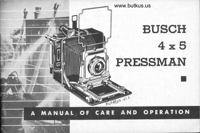
BUSCH 4X5 Pressman User manual
User manual for BUSCH 4X5 Pressman. 32 pages in English. Read the original PDF, download or print a copy without registration.
32 pagesEnglish4.3 MB PDF
Loading your manual…Open PDF directly
Document details
- Brand
- Busch
- Model / document
- BUSCH 4X5 Pressman
- Document type
- User manual
- Language
- English
- Pages
- 32
- File size
- 4.3 MB
- Category
- Film cameras
- Document date
- Not specified in catalog
Search available document text
Find a term, then jump to its page in the original PDF. Image-only pages may not be searchable; check the PDF for exact wording and diagrams.
Page 3 · Read text
BACK VIEW
E Optical Viewfinder Eyepiece and Parallax
g ControlRangefinder A Handle Adjust-  Eyetube          ment Screwg    foc!,slng Hood  m Ha nd le Stra p   Lock Screw
m Revolving Back  @ Focusing Hood
    Release                         Rel ease
tsts Parallax Adjustment on Sports Finder
View original page 3Page 5 · Read text
l
       F[JREITI)RD.I t !  t                                                        il
          Your 4 x 5 camera is the finest, most advanced
            press-type camera on the market. It is compact-
              fully l-inch smaller in all dimensions than any other
          American made 4 x 5 camera-yet nothing is
             sacrificed in rugged construction and desirable features.
          Your camera combines improvements of existing
             features PI.iUS many new developments-all working
            together to make picture-taking easier, faster and
          BET1fER trhan ever before in this film size. Your camera
             will give you years of service with ordinary usage and
             sensible handling. It is guaranteed for a period of
           one year against defects of manufacture and material.
            Congratulations on an excellent choice! As the
            years go by your investment will pay for itself time and
            again in enjoyment, interest and pride of ownership.                                                                                                                   .:l;
                                                                                                                                                                                                               si

                                                                                                                                                                                           fi
L                                                                                                                                                                                       fi
View original page 5Page 6 · Read text
www.butkus.us


rl*1 . PR,ESS DOWN TATCH BUTTON  O RE'YIOVE SLIDE
*j  This .will release_ the door assembly     Be sure the shutter is closed.ftl  pgomittiqg the fingers to grasp th-e    *t"  or tne door.H                     O COMPOSE SCENE IN FINDER,
; O DR.AW DOOR DOWNWARD       Move toward or away from zubject for                                                  desired result.$   l.Vhett.the_side brqce_s click into posi-$   tion the door will be at 90o to the
$   film plane.               O SET ,SHUTTER
$l*                                                S9t gpeed dial of shutter and aperture o PUtt tENs ,nouNT out         oJ lens to correct exposurel Cock
*   With focusing rack in rearmost posi-        shutter.$|  tion pull the lens mount firmlv ae-ainst     thq,          infinity                           grasling                    while                                        the                  .stops$|                        o FOCUS    puu-out               r(nobs.                       by pustrlng                    Locl(                              mov-s$   able knob to the right.-                 pse range finder or focusing scale to                                       determine correct footage. Consult
                                                                              necEssary. O tlFT SPORTS FINDER                 depth of field chart if
    and rear finder e{ect. Or, draw out eye                      O TRIP SHUTTER     tube. of optical -view finder and adjust    paralrax control_                         while observing scene through finder.
 O INSERT FIM'I PACK        O REPTACE SLIDE
    or cut film holder.                                     If using rum pactr pull tab immediately.
flr5
II
View original page 6Page 7 · Read text
lrijliriiii
 ff                                                                                                                                                                                    Digitally signed by mike butkus  iit                           mike            DN: cn=mike butkus,
                                                                                                                                                 o=orphancameras, ou=29,
                                                                                                                                                       email=mike@butkus.org, c=US
                                                                                                                                                                  Date: 2019.01.08 19:59:22 -05'00'  HOTDING THE CAMERA    butkus
tj#
fi#   One of the most important points to observe when hand-holding a camera
      steadiness. To achieve this, the following rules should be noted:
f#
       (a) Avoid using shutter speeds slower than 1/50th of a second. While it islift      possible to get needle-sharp negatives at even L/L0 of. a second, it is only
     due to good luck or extremely steady hands. For consistent sharpness, use
$,iii    L/50th of a second or faster.
i$     (b) Cradle camera in both hands. Press the forearms against sides of the
     body for added rigidity. Keep elbows in. Slip the hand through the strap
      (Y) and curl fingers around the edge of the case. The handle strap can
     be adjusted. Simply loosen one of the locking screws (X) with a coin
     and move to the next perforation.
       (c) Brace back of camera against the faee with the eye close to
      the rear section of the view-finder.
       (d) Squeeze, do not jab the shutter release. Jerking the shutter
      release increases the probability of moving the camera while the
      film is exposed. Use a cable release for hand-held pictures.
     Follow these simple directions for hand-held shots and your
      pictures will be consistently clear and sharp.
View original page 7Page 8 · Read text
www.butkus.us

                      SPORTS FINDER
                     -    The sports finder (R) can be put in proper position by
                                            lifting forward and upward. The rear sight is
                                  positioned in a similar manner. The construction
                                       of the front frame allows  it to be used with both
                        the vertical and horizontal positions of the revolving back.

                  The rear aperture (AA) can be raised and lowered to match
                       distance of subject from camera. This is known as parallaxI             correction and permits you to see the actual area "seen" by the lens.                                         ii;iffiii:i:  i:  i ii:i:  lili:    i t,:   i i,i:   i iii iii:iii
              When using the sports finder, keep the eye as close to the rear
         peep sight as possible. This enables you to see the field of view as it will
              appear on the film. This type of view finder is extremely valuable            ffi
     in sports and fast-action photography.  Its design permits more rapid framing            ffi                for such subject matter. Some photographers learn to use the sports ru
     finder with both eyes open. When doing so they are continually aware of the
                 location, distance and details of the moving subject. Normal vision
         in both eyes, and some practice, are the two important requirements here.
                                           7                       ffi
View original page 8Page 9 · Read text
I

          OPTICAT VIEITFINDER

                  Grasp the eyepiece (T) (rounded rear portion) of the viewfinder and
                 draw it back until a definite click is felt. This permits its use in comfort-
                    able fashion even with the film pack adapter in place. Ifsers wearing
                       glasses will find this viewer easier to employ.
                  Unlike comparable finders this instrument contains a more elaborate
                       optical system which permits coverage for both vertical and horizontal
                       positions of the revolving back, and without an increase in bulk.
                    Before rotating the back of your 4 x 5 Camera be sure to push the view-
                      finder tube (T) forward into closed position.
                PARAIIAX CORRECTION-Turn eyepiece (T) left or right, setting the
                      indicator opposite the footage number to make the correction.ffi. ,E
            TO SET MASK FOR VERTICAI COMPOSITION-Draw mask upward.
                      Insert it from the side, thus changing the position of the mask opening
                   to vertical. Holders should be inserted into the camera FROM THE
              BOTTOM. This prevents interference with the viewer.
                MASKS-Since the 4 x 5 Film Pack Adapter can be furnished with a
               ',ffi         lYa,x4Ya reducing insert, masks are available for that format. On orders
                   for masks-SPECIFY FOCAL LENGTH OF CAMERA LENS ANDf"+{'4ffi                   .;     FILM SIZE.

                                  'i.ffi
View original page 9Page 10 · Read text
www.butkus.us
                FO CUSING THE CAMERA

Two generous-sized, kntrled focusing knobs (F) are provided, one at each
side of the drop-hed. This enables you to foeus with'either hand-a
decided adyantage in many picture-taking situations. The rack-and-
pinion gears of the focusing knobs are so adjusted.that just the proper
degree of tension is provided, preventing any possibility of accidentally
jogging or shifting the lens out of focus once it has been adjusted.
The focusing knob at the right side of the camera (as you hold the camera
with the lens facing away from you) has a smaller, secondary knob (H)
which is the lock-knob. By tightening this knob, after you have estab-
lished sharp, critical focus, the rack (G) is locked securely so it cannot
slip or be jostled out of position. A mere twist of the lock-knob (H) locks
or unlocks the focusing rack (G). It is not necessary to exert considerable
force to lock this control. Normal finger pressure will suffice for all
practical purposes. Any unlocking and re-focusing operations can then
be performed with a minimum of delay. Focusing is the first and most
important step in the photographic process. Your camera offers three
different methods of focusing: (1) the scale (E); (2) the ground glass;
(3) range finder (O). The operation of each is described'in detail on
the following pages
View original page 10Page 11 · Read text
FOIUSING SCATE

      The scale (E) is equipped with a "cursor" similar to that of a slide rule.
          It is actually a small magnifier with an etched indicating line. To operate,
'ill      simply superimpose this line over the line next to the desired footage.
      Use the focusing knob (F) for this purpose. View the scale from directly
      overhead for greatest accuracy.
$      (Estimated distances are never exactly accurate. Depth of field will
ffi      compensate for most minor errors in judgment, but do not rely too much
      upon depth of field to correct your errors and give clear, sharp pictures.
$     For needle-sharp pictures, the focus must be critically established. The
       scale is accurate, but it cannot overcome a glaring error in judgment.
       For perfectly focused pictures every time, determine footage as accurately
       as you possibly can)
      Remember-distances  are measured from t}rre film plane to the subject,
      not lens to subject. Several scales can be installed to accomodate addi-
        tional lenses. This practice allows the use of one range finder with several
       lenses. Simply focus, and transfer the reading of the coupled scale to
      any other scale which matches the focal length of the lens in use.
                                            10
View original page 11Page 12 · Read text
www.butkus.us

                CTOSE-UP PHOTOGRAPHY

The extra-long bellows extension provided in your eamera facilitates
photographing small objects at close range. A normal lens can be used
at double its focal length, permitting film images equal in size to the
actual subject. Focusing must be confined to the ground glass. The scale
(E) and the range finder (O) do not operate at elose quarters. With the
ground glass, the photographer can determine focus, coverage, composi-
tion and depth of field at the same time . . . with great accuracy. When
us.ed beyond normal focusing range, f values change, and some compen-sation must be made in exposure. Generally doubling the focal length
requires an increase of four times normal exposure using any one dia-
phragm setting. Measure from the shutter to the ground glass.
 FL    Focal Length     EXAMPLE: 6" lens; 10" bellows extension V -                       6 x 6   36      1                                     10 x 10- 100-   2.8 FLxFL^=o'fr]--LenstoFilmDistanceIncrease in Exposure
FI|P-BACK INFIN|TY STOPS-Infinity stops (J)
on foeusing rack (G) flip back when you want
to by-pass them with the lens. Infinity stops
are synchronized with your lens. Additional
slops can be added to accommodate a difierent
focal-length lens.
                                  11
View original page 12Page 13 · Read text
GROUND GTASS SCREEN

Open the shutter (B) and expose the ground glass to view'by pressing
catch (Z) at bottom. The hood shields the glass from reflections. Turn
the focusing knobs (F) forward or backward to locate the plane of max-
imum sharpness.
The ground-glass focusing screen may be used with the camera hand-
held or tripod supported. After sliding the holder or adapter between the
camera back and the spring-back unit which contains the ground glass,
the film automatically lies accurately in the focal plane and occupies the
samir position as the ground-glass focusing screen. The ground-glass
shows the image projected by the lens in full negative size, in color, and
up-side-down (because lenses invert images). With a little practice you
will be able to study a picture in this inverted position and determine
critical focus and depth of field. Use the lens at its maximum aperture.
After focusing, the lens must be stopped down to the desired ap'erture.
The actual depth of field can be determined by observing the screen image
while operating the shutter aperture lever to the desired f stop. Close theshutter (B) before withdrawing the dark slide from film carrier.
The screen is scribed for use with 3YE x AYq filr:l packs if an insert is
used in the normal adapter.
By loosening set screw (V) at top, the hood can be removed from the
camera to permit measuring image size, etc.
                                   t2
View original page 13Page 14 · Read text
www.butkus.us

                  THE REVOTVING BACK

     The revolving back permits you to change from vertical to horizontal
      format without removing the camera from the tripod. Used in conjunction
      with the sports finder, it is possible to take hand-held pictures with the
      back in vertical position. To revolve back, grasp knurled knob (W) at bot-
      tom and draw it back. Now turn entire back in desired direction. It is not
       necessary to retain hold on knob (W) once back is out of position. Back
       will click automatically into 90, 180, 2?0 and 3G0 degree positions. To
       return back to normal position, merely draw back on the locating screw
      (w) and turn into position. It will click into place automatically.
     When using revolving feature vertically with camera hand-held-rotate
      back to position holder opening at bottom. In other position holder would
      protrude and prevent use of viewfinder.     You will find this to be one of the most useful features of the eamera. W
      Whatever the subject matter may be, examine it from the standpoint of
      both vertical and horizontal composition. A definite improvement may
       result from this action.
                                           13
L                      ffi
View original page 14Page 15 · Read text
RANGE FINDER
Designed to show the exact focus of the lens at various distances by
superimposing two images in the eye-piece (U), the rangefinder (O)
enables the photographer to establish sharp focus in a minimum of time
by adjusting focusing knobs (F) until both images are superimposed.
Rangefinders are synchronized to each individual lens. The rangefinder
must be re-set if the lens is to be changed, even though focal lengths may
be identically marked. Rangefinders are of particular help where the
need for rapid focusing is felt: sports . . . animal  . . . child photography.
Cameras equipped with rangefinders are accompanied by additional ex-
planatory literature.
Your rangefinder should be checked periodically to insure accuracy.
HOTDERS qnd ADAPTERS-FiIm pack adapters are manufactured es-
pecially for use with your 4 x 5 camera. No matter what make of film
earriers you have, the following precautions should be taken when using
them: (a) be sure holder is seated firmly in camera back before pulling
slide (b) when holders are not in use, pull slides out to relieve pressure
on light traps (c) practice loading until you can do it quickly and
accurately.
                                  L4
View original page 15Page 16 · Read text
www.butkus.us
            FILM HOTDERS AND ADAPTERS

T     Onlv standard American press-type holders and adapters should be used
      with your camera.                      Yhgr^using ftlm carriers, be'slre they are firmly     I     seated in camera back before pulling slide.
 a    CUT FILM HOTDERS-Use standard cut film holders. To load. remove the
      4""F slide and open the hinged end of the holder. open the film in total      darkness. Handling by the edges onlv, locate the notch on one of the
       short dimensions of the sheet of film. When this notch is on the top edge
     and toward the right the emulsion side is facing you. Slip the film into
      the two channels of the holder and slide into plic-e, emulsion side facing
     you. Close the hinge and replace the dark slide.
ll      Film carriers of all types should be periodically dusted. A suction cledner
              assist.lt      will
    4 x 5 FltM PACK_ AD-A_PTER (with 31A x 4Va inseril-Open by pushing
      knurled chrome plated knob at top sideways. 4 x 5 film pacl inserted
      as usual. This adapter can be equipped with an insert that permits the
       use- of smalle-r, more economical 3Y+ x 4Ya film. Just lay inserl in adapter
      with notched short edge toward opening knob. Ths insert will auto-      matically fall into correct                                           fnsert 3Y+ x 4Va film into adapter                                    -position.     with tabs lying in the notched end. Spring pressure will hold flm bnd      insert firmly in position.                  q#$
View original page 16Page 17 · Read text
THE RAPAX SHUTTER

             This shutter is available in three basic types-the standard (non-flash),                3'X"            the      (for instantaneous repeating  electronic flash), and the Full
             Synchromatic (for all types of delay and flash equipment).fur*Wt'ul
         TO PRE-SET THE SHUTTER-The Full Synchromatic RApAx Shutter i'b a
               presetting type of shutter; before exposure can be made, the shutter must
            be set or "cocked". This is accomplished by moving the setting lever,
              extending from the top of the shutter, to the right (with lens facing you)-
             the full length of the slot in the dust shield attached to the lever. 'The
               shutter is now set, and ready for making the exposure by pressure on the
               cable release, or by pressing on the release lever located on the left-hand
               side of the shutter.
           FOR TfME EXPOSURES-"T" or Tirne Ecposure is used for exposures of
              Iong duration. Turn the speed cam (the outside knurled disc) until the
                 letter "T" is at the indicating line on the shutter. Set the shutter with the
                                      release              lever                 on                      the                             top, and                                   by pressure                                                             lever                                                        the                                                       on the                                                                              left-hand                                          bn
                                 (with                      the                                         lens facing                    si.de of                                                              cable                                           you) or                                                   by                                                                     release.                                                                         This                          shutter,                                                                                   action      I
                will cause the blades to open and remain open until the release lever is
              again trifped (in the same direction) to close the blades. NEVER reset the
              shutter when fhe blodes ore open; domoge to the shutter moy result.

                                                    16
View original page 17Page 18 · Read text
www.butkus.us

 FoR ButB ExPosuREs-"8" or Bu-Lb E-rposure is used only for making
 prolonged-exposures. Set the speed indicltor to "8" r"a r"t inl rfr"tt"i as outlineil above; then trip the ielease lever or press on the cable release.
 This will- open the shutter and keep it open   iong as pressure is main- tained. As soon as pressure is relLased-, the""shutler witt close.
 FOR INSTANTANEOUS EXPOSURES-Turn  the speed cam to the exposure
 desired, and set the shutter. (When setting to L/ 4OO sec., a stight-additional
pressure is required to overcome the resistance of the boo'ster spring).
To release, just press the cable release or release lever on the l"fa;c[;%i
the shutter. No harm will befall the shutter if the speed.
indicator is set between any two given markings;- Uut
fot: correct exposures,  it is more satisfactory to -sei the
indicator accurately at the desired e*posure. Speed of
the sh_utter, if used at intermediate settlngs, is noi guar-
anteed at those settings.
FOR QUICK GROUND-GLASS FOCUSTNG   Leave thespe-gd ri_ng set at.the selected speed (any- speed from
Bulb to L/400 sec.), merely cock [he shutter .ird d"p"e""
the Press-focus lever (BB) clockwise. This action will
gpen the blades and keep them open until you have
focused.


                                      L7
View original page 18Page 19 · Read text
RAPAX SHUTTER (cont.)

To close the blades, just lift the Press-focus lever counterclockwise to its
original position. Since the shutter has already b"9! cocke{, you are
reidy to trip the release lever for an exposure. Although the shutter
must be cocked before using the Press-jfocus lever it is not necessary to
recock the shutter before exposing.
TO OPERATE THE SHUTTER FOR SYNCHRONIZED FTASH
To connect the shutter with the flash gun or unit, fasten the end of elec-
trical connecting cord to the connector posts projecting from the lower
right-hand side of the shutter, and to the other end of the synchro outlet
in the battery case. Use cord #4400. (twin post)
It is not necessary to observe polarity when connecting a high speed
electronic flash unit to the shutter. The connector cord may be plugged
in to the shutter either way.
The Synchromatic-Rapax has the synchronizer delay mechanism adjust-
able for synchronization with a given class of lamp by setting the indicator
lever in lhe notched position opposite the appropriate marking on the
delay scale. Note these markings. From left to righton th9 scale_t-hey are:
the white "M", the red "M", the white "X", and the white "Off." Also
note that the speed markings are in black for 400, 200, and 100. The
                                     18
View original page 19Page 20 · Read text
www.butkus.us

                 RAPAX SHUTTER (cont.)

markings 50 and down through B & T are in red. For most efficient syn-
chronization with Class M (20 milliseconds) lamps use the white "M"setting of the synchronizer for the speeds marked in black and use the
1ed "M" setting for the speeds marked in red. If an electronic high speed
fla3h unit of the Class "X" type is to be used, set the synchronizer dLlay                 (BB}
lever at "X".
This gives excellent synchronization at all shutter speed settings. If Class
F lamps are to be used, they will be in synchronization at the red speeds
of 50 and slower when the synchronizer is set at the red "F".
On larger shutters black M-F and X markings replace the whitesettings described in the text.
COCKING THE SHUTTER AUTOMATICALLY COCKS THE SYNCHRONIZER AT ALL                                    , l/5
sETrtNcs oF THE DELAy rNDrcAToR ExcEpr rN THE "oFF" posrrroN.
If you wish to-operatq the Press-focus lever at this point, with the lamp
connected to the.synchronizer, you may do so without danger of settingoff the lamp. (BB)                             ..s.I
The shutter rs hand-trippgd or released, and automatically
s,ynchronizes the peak flash of the lamp with the maximum
shutter opening.
CAUTION: rnn rrME DELAy rNDrcAToR sHouLD BEsET To rHE DE-
                                    19
View original page 20Page 21 · Read text
RAPAX SHUTTER (cont.)

        SIRED POSITION BEFORE SETTING TIIE SHUTTER; IF TIIE SHUTTER IS ALREADY
        cocKED BEFoRE MovrNG THE MrLLrsEcoND rNDrcAToR FRoM "oFF" posrrroN To
       ANY OTHER POSITION. THE SYNCHRONIZATION MECHANISM 1VILL NOT BE COCKED.
 f$     In such cases, simply release and then re-cock the shutter.
       Should the shutter be cocked with the lamp in place, the time-delay$$$         indicator m?V, if necessary, be moved from Red "M" to White "M" orriffi       White "M" to Red "M" but not to the OFF position. rF rr rs MovED To
      AN "oFF" posrrroN wrrr THE SHUTTER cocKED AND THE LAMe rN pLAcE, THE
       LAMe lvrr-r. FLASH. To make this change in setting, simply remove the
      lamp from the battery case and then set time-delay indicator to the
         desired position. If the time-delay lever is at a given setting, it does not
        require re-setting after each exposure as long as the same type of flash
       lamp is used.
       With the time-delay indicator in the OFF position, no electrical eontact
         is made.
       The shutter speeds may be re-set at any time after the shutter is cocked
       without firing the lamp.
       BEFORE PUTTING YOUR CAMERA AWAY, rf rS RECOMMENDED THAT yOU RELIEVE,
                                             20
View original page 21Page 22 · Read text
www.butkus.us

                 RAPAX SHUTTER (cont.)

TI{E TENSION ON TITE CONIBOLLING SPRINGS OT'TT{E SITUTTER BY SETTING TIIE
SHUTTER AT A SLOW SPEED AND TRIPPING.
HERE   f S WHAT lS MEANT BY "M", "F", & "X"-There are in common
use for between-the-lens shutters three general types of flashlamps class-
ified according to their "time-to-peak" ratings as follows:


       TYPE                 IIME.TO.PEAK             TYPICAL EXAMPTES
                                                         Wertinghoure No. 5, ll,  22.    Clqss M       2O milliseconds          G.E. No. 5, 11 ,22.
                                                            Sylvonio 25, 0, 40 etc.
                                                          We:tinghoure 5M    Closs         5 milliseconds          G.E. SM                                                            Sylvqnio 5F
                                                                      Electronic high                                                                                rpeed:
                                                                                                   alc.    Clqss x      O milliseconds          Kodolron,

D}N'T use oil on the shutter. Special greases have been applied, making
it unnecessary to use any additional lubricants. OiL u:i.Ll ruin th.e shutter.
                                    2L
View original page 22Page 23 · Read text
THE SUPERMATIC SHUTTER

              FOR NON-FIASH PHOTOGRAPHY- Set the shutter for automatic ex-
                  posure of. l/400, L/200, I/L00, 1/50 and L/25 second by turning the
                   spEED coNrRoL nrrvc until the left-hand (black) spEED porNrER is opposite
                   the 400, 200, 100, 50, or 25 index line.
                    Set the shutter for exposure of L/L0, t/5, L/2, 1 second, B and T by
                    turning the sprnn coNrRoL nrrrrc until the right-hand (red) spEED porNTER
                         is opposite the 10, 5, 2, L, B, or T index line. Intermediate speed settings
                      will not give intermediate shutter speeds.
                         S,et the lens opening by moving the appnruRE porNrEn until it drops into
                  the click stop beneath the desired f/  opening.
                Cock the shutter by pushing the cocrrNc LEvER in the direction of the
                  BLADE ARREsTER BUrroN until it catches. The shutter must be cocked for
                        all speed settings, including T and B.
               To make an etposure at speeds ranging from L to L/400 second, pressffi                    the nnr,sesE LEVER carefully. To make a Time exposure, press the nrr.resr
                     LEvER once to open the shutter and again to close it. For a Bulb exposure,
                               it will be necessary to press the nnr,sesn LEvER to open the shutter and to
                   continue the pressure to hold the shutter open for the desired length
                   of time.                                  ffi
                                                      22

                                                                         - ..,..... :   .. ..',-3c,-
View original page 23From the M. Butkus archive. Original publisher and archive notices are retained.
Check the model and edition against your equipment.
PDF verified 2026-10-10.