Camera accessories
Chinon Wireless Remote Control User manual
User manual for Chinon Wireless Remote Control. 8 pages in English. Read the original PDF, download or print a copy without registration.
8 pagesEnglish0.4 MB PDF
Loading your manual…Open PDF directly
Document details
- Brand
- Chinon
- Model / document
- Chinon Wireless Remote Control
- Document type
- User manual
- Language
- English
- Pages
- 8
- File size
- 0.4 MB
- Category
- Camera accessories
- Document date
- Not specified in catalog
Contents
Search available document text
Find a term, then jump to its page in the original PDF. Image-only pages may not be searchable; check the PDF for exact wording and diagrams.
Page 2 · Read text
www.orphancameras.com

OPERATING INSTRUCTIONS

Thank you for purchasing this quality Chinon Product.

This remote control set was developed through the most experienced 35 mm SLR camera technology
for use with Chinon CE-4 compact SLR camera and conforms to applicable government
communications regulations. Although a license is not required, please be aware that modifying or
disassembling this unit may lead to violations of such regulations.www.4.butkus.org


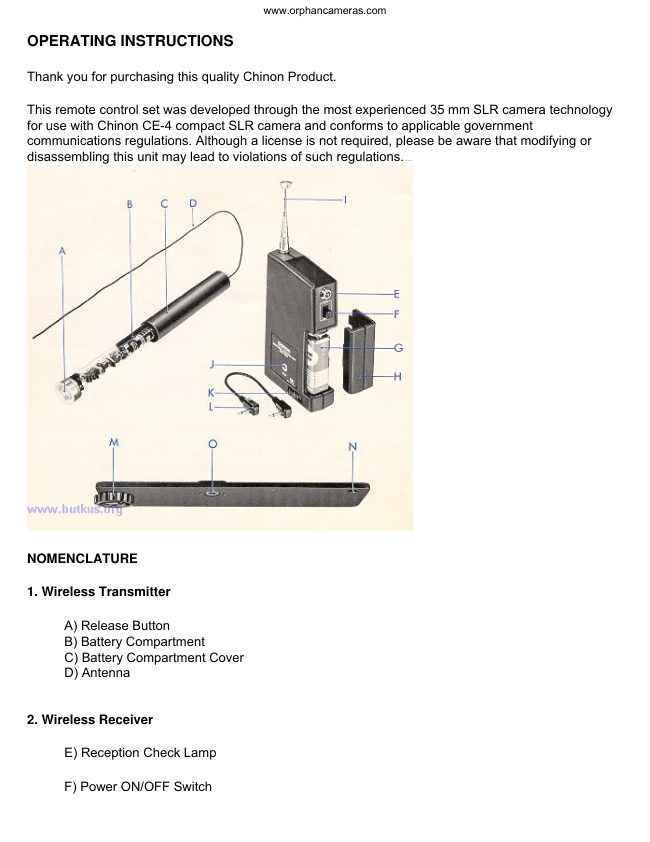
NOMENCLATURE

1. Wireless Transmitter

      A) Release Button
      B) Battery Compartment
     C) Battery Compartment Cover
     D) Antenna


2. Wireless Receiver

      E) Reception Check Lamp

      F) Power ON/OFF Switch
View original page 2Page 3 · Read text
www.orphancameras.com

     G) Battery Compartmentwww.4.butkus.org

     H) Battery Compartment Cover

         I) Antenna

       J) Output Jack

      K) Mounting Screw

      L) Connecting Cord

3. Mounting Bracket


     M) Mounting Screw to Power Winder

     N) Mounting hole to Wireless Receiver

      0) Tripod Socket


BATTERY INSERTION

A. Wireless Transmitter

1. Unscrew and open the battery compartment cover.

2. Install one "AA" size battery.

3. Close the battery compartment cover.

B. Wireless Receiver

1. Set the power switch to " OFF "

2. Press the battery compartment cover in direction to open.

3. Connect and install MN1604 battery (9V transistor type radio battery).

4. Be sure that battery connector wires are not pinched when closing the battery compartment cover.


SPECIFICATIONS

A. Wireless Transmitter (RC-510)
View original page 3Page 4 · Read text
www.orphancameras.com

· Output Power ....................Less than 1mw.

· Frequency .........................27.045 MHz

· Moderation .......................A1

· Oscillator ...........................Crystal control

Occupied Brand Width ......Less than +10 KHz

Spurious & Harmonic ......Less than 4 x 10⁻⁹W

Temperature Stability ........Within +0.01% ( - 20° +60°)

Voltage Stability Within .....+0.01% (voltage 80 - 120%)

Antenna ................................50cm Wire-antenna

· Constant Distance ............Approx. 40 meters (130 ft)

· Battery ...............................One "AA" size battery

· Battery Life .......................Approx.10 hours

Size ....................................28 (D) x 148 (L) mm (1.1~ x 5.82~)

Weight ...............................Approx.10Og. (3.53 oz.)

B. Wireless Receiver (RC-550)

· Frequency .......................27.045 MHz

· Receiver-system ............Single Super heterodyne

· IF .....................................455 KHz

· Sensitivity ......................25 dB

· Band-Width ...................Less than 15 KHz ( - 60 dB)

· Remote Control ............Possible with "Switch ON/OF F"

· Battery ..........................One MN 1604 (9V) Transistor
                      Radio Type
View original page 4Page 5 · Read text
www.orphancameras.com

· Size ..............................110 (H) x 65 (W) X 24 (L) mm
                           (4.2" x 2.5" X 0.94")

· Weight .........................Approx.125 9. (4.48 oz.)

(Specifications are subject to change without prior notice.)

OPERATION

Transmission and Reception Range, as well as receiving quality of a wireless transmitter and receiver
system vary according to surrounding conditions. These functions should therefore be tested before
taking the actual photography.www.4.butkus.org

       1. Rotate the mounting screw (Fig. M) to securely attach the bracket to Chinon Power Winder
      dedicated for CE-4 compact SLR camera.

       2. Use mounting screw (Fig. K) to firmly install the receiver to bracket mounting hole (Fig. N).

       3. Use a connecting cord to connect receiver output jack to the remote control socket of the
     power winder.

       *Set the power switch of power winder to ''OFF " position.

       4. Extend the receiver antenna fully.

       5. Set the receiver power switch to " ON "

       6. Push the release button of the transmitter and ensure that the receiver check lamp
       (Fig. F) lights.

         *If the check lamp does not light, check battery of transmitter and receiver. The check
     lamp does not light if either of the batteries is improperly installed or depleted.

       7. Lock the shutter release button of power winder by sliding the release lock button (only
       for model PW-530).

     *Do not lock the shutter release button of power winder model PW-540.

       8. Set the C/S dial of power winder to the " S " (single frame exposure) or " C
        " (continuous) position.

       9. By depressing the release button, you can control Chinon power winder remotely at a
      distance of approximately 40 meters (130ft).


REMOVAL OF WIRELESS CONTROL SET
View original page 5Page 6 · Read text
www.orphancameras.com

       1. Set the power switch of power winder to " OFF ".

       2. Release the shutter release lock of power winder.

       3. Set the power switch of receiver to " OFF''.

       4. Disconnect the connecting cord from the receiver.


*If you disconnect the connecting cord without releasing the shutter release lock, the shutter may be
released.

EMPLOYABLE RANGE

       1. Noise or faulty operation can be experienced if wireless transmitter and receiver are
      operated at excessive distance from each other.

       2. Transmitting range varies according to surrounding conditions. With new batteries in
      both wireless transmitter and receiver, and in absence of interference from buildings and
      other structures, the transmitting range is approximately 40 meters (130 ft.).

       3. Sensitivity can be reduced due to signal reflections and scattering if used near metallic
       structures or within narrow ferro-concrete rooms. If this type of situation prevails, separate
      wireless transmitter and receiver from such structures by 1 to 2 meters (3 to 6 ft).

       4. Also, the wireless transmitter antenna must hang vertically and the receiver antenna
        fully extended. Bundling or shortening the antennas reduces transmitting range.

       5. Transmission range decreases as batteries become depleted. Observe receiver check
     lamp procedures and replace batteries when required.
View original page 6Page 7 · Read text
www.orphancameras.com


NOTE:

       1. Avoid using in or near airport or aircraft.

       2. Use in countries other than where purchased may be restricted by law.

       3. Avoid using in locations subject to high temperature or Humidity.

       4. Do not lift, handle or bundle wireless transmitter wire. Bundling or stretching may also
     damage the transmitter.

       5. Increasing antenna length or modifying the transmitter structure may lead to damage and in
       addition violate government communications regulations.

       6. After each shooting session, be sure to turn off camera main switch, power winder switch,
       transmitter switch and receiver switch.

* Batteries should be removed when not using the equipment for long periods of time.

    CHINON INTERNATIONAL CORP. TOKYO, JAPAN.
View original page 7From the M. Butkus archive. Original publisher and archive notices are retained.
Check the model and edition against your equipment.
PDF verified 2026-10-10.