Flashes & lighting
Computer Automatic Bounce Electronic Flash User manual
User manual for Computer Automatic Bounce Electronic Flash. 13 pages in English. Read the original PDF, download or print a copy without registration.
13 pagesEnglish2.6 MB PDF
Loading your manual…Open PDF directly
Document details
- Brand
- Computer
- Model / document
- Computer Automatic Bounce Electronic Flash
- Document type
- User manual
- Language
- English
- Pages
- 13
- File size
- 2.6 MB
- Category
- Flashes & lighting
- Document date
- Not specified in catalog
Search available document text
Find a term, then jump to its page in the original PDF. Image-only pages may not be searchable; check the PDF for exact wording and diagrams.
Page 1 · Read text
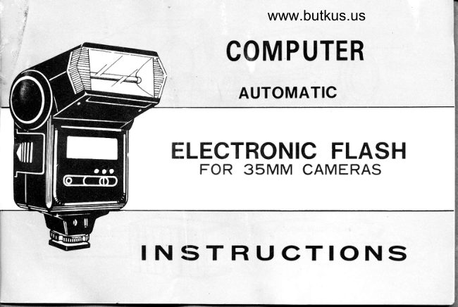
www.butkus.us
     COM PUTER

         AUTOMATIC

  ELECTRONIC FLASH
     FOR 35MM CAMERAS

INSTRUCTIONS
View original page 1Page 4 · Read text
www.butkus.us


  O IDENTIFICATION OF PARTS

1.   Flash Window                    9.   Bounce Angle lndicator
2.   Battery Compartment Cover       10.  Exposure Guide Table
3.  Auto Sensor                                 1 1.   Auto Check.
4.   Auto-Manual Switch             12.  On-Off Power Swr'tqh
5.  PC Cord Socket               13.  Ready Light
6.   Locking Knob                    '14.  Test Button
7.  PC Cord                      15.  Hot Shoe
8.   Bounce Head                  16.  Super Wide Lens
View original page 4
Page 5 · Read text
O INSERTING THE BATTERY
Silde back the Battery Compartment Cover and
insert into the compartment four AA size penlite
Alkaline batteries according to the polarity  in-
dicated in the compartment. Remove batteries
from the unit when it is not used for any length
of time.
   MOUNTING THE FLASH
Raise the rotating shoe lock to its highest position
and slide the shoe into the accessory clip on top of
the camera. After the shoe is inserted as far as it
will go, turn the knob in the opposite direction to
lock.
lf your camera  is equipped with Hotshoe connection
(the flash electrical connection built into the clip)
then no further electrical connection is needed.
lf the camera has no Hotshoe, then use the PC cord
supplied by inserting one end into the PC socket in
the shoe of the flash and the other end into the
flash connection on the camera.
View original page 5
Page 6 · Read text
www.butkus.us
O OPERATING THE FLASH
Turn the switch to the "on" position. Within a few
seconds the Ready Lite will go on indicating the
flash is fully charged and ready to be fired. After
not using for a long time, reform the capacitor by
f iring 3-4 shots with the Test Button.
                                                           Viq
After the flash is  f ired,the Ready lite will go off.                    Feef
Never fire the flash until the Ready Lite comes
on again. When this recycling time is more than
45 seconds, the batteries are weak and should
be replaced.
Be sure to turn the flash off when no longer using
to conserve the batteries. IMPORTANT: Even after
turning off the flash unit the Ready Lite may
remain on because it is powered by the capacitor
and not the batteries. EventuallV,the capacitor will
bleed out and the Ready Lite will be extinguished.
View original page 6Page 8 · Read text
www.butkus.us
    O AUTOMATIC OPERATION
       1. Set the Auto-Manual Switch to the center or
             feft to the position marked "artt6,' (orange
            or green).
       2. On Exposure Guide-Table, an orange,t,, in_
            dicates the automatic orange setting f/stop (Ex.
        ASA100 orange setting: (f2) and a green ,r,,
            indicates the automatic greut setting f/stop (Ex.
        ASA100 green setting f4) see page 5.
      3. Your flash unit will provide correct exposure atI             all distance trom 2.5 to 12m for orange setting
          and 1.2 to 6m for green setting.                   (MANUAL) {AUTO) (AUTO)
                                           WHITE  GREEN ORANGE
                                                               \         \\                             \--o                       b b
                                                             {r  -.)
View original page 8Page 9 · Read text
O WHAT IS A THYRISTOR FLASH ?
 This flash unit will give you automatically correct exposure every time. Merely by setting
 the recommended f/stop on your camera, the sensor in the flash unit measures thedistance
to the subject and adjusts increases or decreases the amount of light output for correct
exposure.
ln addition to this feature., a new Thyristor (sometimes called as Series Control) circuit  is
built into this flash to provide additional unusual features. In the Thyristor circuit, the
amount of energy used is always in proportion to the amount of light needed.
Thus, at any distance from the subject less than the maximum range, there will always be                                                          l
residualenergy in thelcapacitor for the next flash. At close-up distances where very little                                                                                                                                            *ilight is needed, as much as 90% of the energy may remain in the capacitor after the flash.
This residual energy allows the flash to recycle much faster and be ready to flash again
much sooner (as fast as 0.5 second).
Since you are conserving the energy in the capacitor instead of wasting it, you are also
conserving the energy of the battdries which do not have to refill the capacitor every
time. Thus, this unit provides as many as 800 flasheswith one set of fresh batteries dep-
ending on the distance to subject.
IMPORTANT: Flash will not recycle rapidly on Thyristor circuit when used in the
Bounce position-
View original page 9
Page 10 · Read text
www.butkus.us
O BOUNCE PHOTOGRAPHY
A more natural illumination  particularly for portra-
iture can be obtained when the lighting is coming
from overhead. For this reason, the flash head  is
adjustable for Bounce Lighting to bounce the light
off the ceiling and back onto the subject providing
more diffused overhead illumination.
The correct angle of bounce which the  f lash can be
adjusted depends on the distance between flash
and subject so that the reflected light hits the
subject from the front. Use only light colored cei-
lings not more than 2.5 meters high.
AUTO CHECK. Trre auto sensor will only be ef-
fective within the range shown on Page 2. In order
to'determine whether the distance you are shoot-
ing is within this range. Auto Range Check is pro-
vided for testing. Aim the flash at the subject and
fire with Test Button.  lf the Auto Check flickers,
vou are safely within range. lf  it does not flicker,
change to orange auto position and test again.
 lf still too far, then you must move closer to sub-
ject or change to Manual operation. Note; Auto
Check will not ooerate in the bounce position.
View original page 10
Page 11 · Read text
. PUTTING IT TOGETHE R
1.   lnsert batteries; mount  f lash onto camera;  if
necessary, connect PC cord to Vour camera.
2.  Turn switch on; test fire with Test Button;
wait for Ready Lite before taking picture.
34. For Manual operation: turn Sensor to White
and use exposure table to determine correct f/stop;
38. For Automatic Operation: turn Sensor to
Orange or Green and set camera on Automatic
f/stop as shown on table.
4. Set the correct bounce angle for the (approxi-
mate distance to subiect.) different lighting effects-
5.   Press the shutter release of your camera; the
llash will do the rest.
View original page 11
Page 12 · Read text
www.butkus.us
SPECIFICATIONS

                    ASA25  ASA1OO     400
Guide Number (in meter):                  lz         24        48
Flash Duration:                  1/30,000 to 111,000 sec.
Recycle Time (Fresh Alkaline):   Manual 6 sec. Auto 0.5 to 6 sec.
Number Flashes:                Manual 120, Auto 120 to BOO
lllumination Angle:             35 to S8mm lenses
                                      Orange             G reen
Automatic Range:                                     2.5-12m              1.2-6m
Auto F/Stop:            ASA25 Orange f 11.2         Green   f /2
                      ASA10O Orangef/2          Greenf/4
                      ASA40O Orange  f 14           Green f/B
Color Temperature:                 ldeal for color and black & white film
Mou nt ing   :                  PC cord/or Hot Shoe
Power Source:                 Four 1.5V Alkaline AA Batteries
View original page 12Page 13 · Read text
. CAUTION

1. To avoid being damaged by the leakage of battery electrolyte, remove the
    batteries from the unit when not using.      u             .

2.  For safety, remove the unit from the camera before replacing the batteries.

3. Do not attach your hand to the hotshoe when replace the batteries.

4. Do not expose the unit to sunlight and high temperature over 45oC too long.
View original page 13From the M. Butkus archive. Original publisher and archive notices are retained.
Check the model and edition against your equipment.
PDF verified 2026-10-10.