Camera accessories
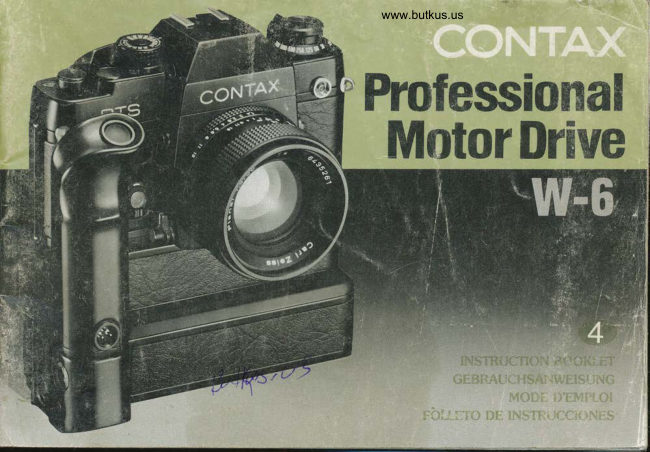
Contax Professional Motor Drive W-6 User manual
User manual for Contax Professional Motor Drive W-6. 68 pages in English. Read the original PDF, download or print a copy without registration.
68 pagesEnglish4.0 MB PDF
Loading your manual…Open PDF directly
Document details
- Brand
- Contax
- Model / document
- Contax Professional Motor Drive W-6
- Document type
- User manual
- Language
- English
- Pages
- 68
- File size
- 4.0 MB
- Category
- Camera accessories
- Document date
- Not specified in catalog
Search available document text
Find a term, then jump to its page in the original PDF. Image-only pages may not be searchable; check the PDF for exact wording and diagrams.
Page 2 · Read text
-rra,rk                yolr for puichasinE the Contax Frofessional          Vielen Danx dats Sie sich fur rlen Contax Prori-
        Nrctor fJrrve {PrflD W-6). The PMD W-6 represents the       Moiorantrieb (PMD W-6) entschieden haben. Der PMD
       culmination of * thorcughgoing quest for a full-scaie    W€ ist der Hohepunki einer sotgfaliigen Entwicklungs-
      muiar d|ive t,lrat e,lables photcgraohing wilh iully           arbeit fr.lr einen universeilen Motorantrieb, der Fotogra-
        auir:rralic operation. The Pl'ilD unit is equipped wiih a      fieren in vollautomatischenr Betrieb ermoglicht. Der
           tr,.ri:"-in irrlerval tirne.' (iniervalonreter) v/hich enabies I      Profi-Motorantrieb  isi mit e!nern eingei:rauten Inten/all-
       s€lt'ngs ranEing from a high-speed operation up to 5       ausloser {lntervalometer) ausEestattei, welcher neun
        fci'rt a maxinruni ii.terval shooting of 60 seconds,         Einsteilungen zwischen Flochgeschwindigkeitsbetrieb
       pern',1[:ng aulomatic operation ;n the a.ito mode and       bis zu 5 Bildern pro Sekun'je und einern maximalen
       ar all sl;uiter speedr'. lt also has an autotnat;c shutoff     Autnahmeintervali vcn 6C Sekunden. Automaiikbetrieb
         1.o picr€ni overwinding of film while iaking piciu!'es,          Lrei Einstellung der Kamera auf automatischen Betrieb
      a*d a pow*r $upply s6{Jrce for the PMD unit that         und das bei allen VerschluRzeilen gestattei.. Ferncr
       dire*ly power$ camera's circuitry. The PMD Power          besitzt er eine Absci,altautomatik, um ein Uberdrehen
      Faek fsatures an eleciromagnetic release button and     des Films beirrr Aufnehrnen zu verhindern und eifie
         ren(,i:: cor'irol capabilliy. and it :ncorDorates a            Stromversorgungsgueile  zur diiei(len Speisung des
        .nuchar.i:rn essentiai lor high-speed continuous           Kameraschaltungssystems.  Besoitderc Merkmale des
       shooti ru Jefore using the PMD W-6, please               PMD-Batteriebehalters sind ein elektfomagnetischer
        familial;:.e yourself ,r'Jtth the contents of this                Ausloser, FernauslOsefunKtion utrd ein fur schnellen
         ir'S:ruct,trr booki-'t sc' thar you will know how to           tiauerbetrieb ausgelegter Mechanismus. Lesen $ie bitte
      npsiat€  ii properly and enjoy k:ng ye,trs cf trouble         vor Inbetriebnahme de$ PMD W-6 diese Bedienungsan-
       fre* ltse.                                                      leitung aufmerksam durch. so diib Sie mit seinen Funk'
                                                                tionen vertraut werden. und ihn richtig bedienen kon-
                                                                nen. Diese kieine Muhe macht sich in jahrelangem,
                                                                storungsfreien Betrieb b€zahlt.
        This insirrj{li;Dn brokie'f is noi lirirted 1o the operat;on oi.1he Ph,'lD        In dreser Bedrenungsanleitung werdcn nicht nur der lllD W'b und
            'yV.8 a:d lle PMD Power Fack whrclr comprise the trasrc             der PMD-Baueiiebehalter,  yys;srrg di€ G:undkompcnenten  des P'oi.
i          co:,r:;1  . 'n it !; the Professronal lrloLor Drive System Dul aiso          Motoranlriebssysrems  darstellen, sondet,t a:ch dre PMD
        .cv":l r.c rrrpf iion of thc PMD Clontrol Corcjs and lhe PNID          Steuerkaoel und die Tasche  fll' den PN4D-Barteriebenslter
        ;)owe. Pack ji.cket so be sure to save lh:s as a han?y retere4ce.      behandeil. Bewanren Sre diese tsecrenungsanleitung cesha,b zum
                                                                         spateren f.l?chschlager gul auf
      2
View original page 2Page 4 · Read text
g
  g
Power Adapter
Fremdstromadapter
Adaptateur d'alimentation
Adaptador de alimentaci6n

                                                         PMD Control Gords 100/300
                                                     1gD-{fr    pMD-Steuerkabet 100/300    m.-^4
                                                                              Cordons de commande PMD 100/300
                                                                                 Cables de control PMD 100/300


           PMD Power Pack                              PMD Power Pack Jacket         AC Control Box
               PMD-Batteriebehalter                           Tasche f0r PMD-BatteriebehAlter              NetzanschluBgeriit
               Bloc d'alimentation PMD                             Etui pour bloc d'alimentation PMD               Boitier de controle secteur
               Paquete alimentador PMD                Funda para el paquete alimentador PMD            Gaja de control de CA
View original page 4Page 5 · Read text
www.butkus.us


250 Film Back
250-Filmr0ckwand
Dos-magasin  250
Respaldo para pelicula 250
View original page 5
Page 6 · Read text
<PMD W.6>
    l) Shutter Release Button
  O Camera-Mount Guide Socket
  O Release Socket
    O LED Film-End Indicator
       lg  Interval Lock Release
               Button
            /- O Interval Dial
      7 O fitm-newind Release Lever
    ?@ Countdown Dial
         I O Frame Counter
                    Mount'Screw         C (D Camera              I'             Handle
              f I O PMD Power Pack/Tripod
             Socket
        l'lO Camera Coupling Terminal
 tp Camera-Mount Guide Socket
 ,'/O Power Pack Connector
   (0 Exlernal Power Socket (withE t/      Socket Cap)
Itz lD Grip
, 1, O Power Adapter Contact
1( O Film Drive Spool
'iY O Camera Mount-Screw
View original page 6Page 7 · Read text
www.butkus.us


              Tripod Socket
         PMD Mount-Screw Handle
               Battery Check Button
               Battery Checker
               Shutter Release Button
         PMD Connector
           PMD-Mount Screw
               Battery Cover Release Button
               Battery Compartment Cover
         PMD Battery Cases
              Terminals
View original page 7Page 8 · Read text
Venmo @mike-butkus-camera  Ph. 2083
PayPal Name  Lynn@butkus.org      www.PayPal.me/lynnbutkus
View original page 8
Page 9 · Read text
ffnmd*rwmhmry ffrmpmrm$ee*s'e

m lnstalling the Power Adaptor    + Anbringen des Fremdstromadapters
                                                 e+ Einlegen det' Batterien# Battery Installation
                               # Ansetzen des Motorantriebsm Mounting the Motor Drive
View original page 9Page 11 · Read text
The PMD Power Pack uses twelve 1.5 V AA-size penlight
   batteries or 1.2 V Ni-Cd batteries which are fitted into two
   battery cases of the power pack. High pertormance
  manganese alkaline batteries are recommended.
 E  Push upwards on the battery compartment cover
   release button and open the battery cover.
 A  Insert six penlight batteries into each of the
   battery cases by matching their polarity with the (+  )
  and (-) signs indicated on the battery cases. lf the
   polarity is mismatched, a reverse current breaker will
   operate to prevent any current from flowing through
   the circuitry.

 g   Insert the battery cases into the left and right sections of the
   battery compartment, making sure that the battery case
   terminals line up correctly with the contacts inside the battery
   compartment.
  Then close the battery cornpartment cover.


                                                                       www.butkus.us

16
View original page 11Page 12 · Read text
www.butkus.us


(Battery Check)
Press the battery check button to see  if batteries are functioning
properly.  lf the needle jumps into the green band of the checker
window,  it indicates that voltage is adequate. When the needle
points to the red band of the battery checker, it is an indicaton
that the batteries are weak and need to be replaced.
lf Ni-Cd penlight batteries are used, the checker will not point to
the green band because the voltage rating of such batteries are
of a slightly lower voltage than the other types. Although this
does not affect performance,   it would be advisable to check for
any signs of change in condition from time to time.
o Use the battery checker button only when necessary, to
avoid battery drain.
View original page 12
Page 13 · Read text
(Precautions with Batteries)                         (Hinwelse zu Batterlen)
o When changing batteries, replace all 12 batteries at    o  Beim Batterienwechsel alle 12 Batterien gleichzeitig
the same time. A mixed set of old and new batteries  will       auswechseln. Alte und neue Batterien zusammen
be incapable of delivering an adequate charge.               verwendet liefern nicht die richtige Spannung.
o  Batteries exposed to cold temperatures (subzero      o  Batterien, die niedrigen Temperaturen (unter 0 Grad)
centigrade)will not always perform adequately and there      ausgesetzt sind, bringen manchmal nicht ihre volle Leistung.
will be times when the camera will fail to advance the film     Es ist moglich, daB die Kamera in diesem Fall den Film
at the preset intervals, and could even result in                  nicht zu den voreingestellten Intervallen transportiert, ja
malfunction of the system. To prevent this, disconnect the     sogar eine Betriebsstorung des Systems ist nicht ausge-
power pack from the motor drive unit and use it as a          schlossen. Um dies zu vermeiden, trennen Sie den Batterie-
remote power source in conjunction with the PMD Power      behdlter von der Motorantriebseinheit ab und setzen Sie ihn
Pack Jacket (see page 56)and the PMD Control Cord (see     als Fern-Spannungsguelle  zusammen mit der Tashe fUr
page 54)to protect the batteries from the cold. When          PMD-Batteriebehdlter (siehe Seite 57) und dem PMD-
batteries temporarily weakened by cold temperatures are      Steuerkabel (siehe Seite 55) ein, wodurch die Batterien
restored to normal surrounding temperatures, they will        gegen die Kdlte geschUtzt werden. Wenn Batterien, die
recover their normal output and be acceptable for further     vorUbergehend durch niedrige Temperaturen beeintrdchtigt
satisfactory service.                                     worden sind, in einen normalen Temperaturbereich gebracht
o When not using the power pack for long periods of        werden, entwickeln sie wieder ihre normale Leistung und
time, remove the battery cases from the power pack and     konnen weiterhin verwendet werden.
the batteries from the cases to pevent leakage that could   o Wenn Sie planen, den Batteriebehdlter fUr ldngere Zeit
damage the contacts.                                              nicht zu verwenden, nehmen Sie die Batteriemagazine aus
o  Since stauring of the battery contacts with grease or     dem Batteriebehdlter und die Batterien aus den Magazinen
perspiration can cause poor electrical contact, make  it a      heraus, um ein eventuelles Auslaufen der Batterien, wodurch
point to wipe the contacts clean with a dry cloth before        die Kontakte beschddigt werden wtirden, zu vermeiden.
placing the batteries into service.                o  Fett und SchweiR auf den Batteriekontakten konnen die
                                                       Ursache frir einen schlechten elektrischen Kontakt sein.
                                                  Machen Sie es sich deshalb zur Regel, die Kontakte vor
                                          dem Einsetzen der Batterien mit einem trockenen Tuch zu
                                                                 sdubern.
View original page 13Page 14 · Read text
www.butkus.us


The PMD W-O is mounted direAtly to the base of the camera,
and the PMD Power Pack is normally mounted directly to
the base of the motor drive. Since the power pack is fitted
with its own release button, it can be used with the PMD
Control Cerd lgr remote control photography.
(Profeeelonal Motor Drlve W€)
The Professional Motor Drive screw-mounts to the bottom of the
camera. Align the motor drive's camera-mount screw with the
camera's tripod socket (and see that the camera's motor drive
mount guide studs are properly seated in the camera mount
guide sockets on the PMD). Then, screw the motor drive firmly
into the camera, turning the screw clockwise. Fold the mount-
screw handle in after mounting.
View original page 14
Page 15 · Read text
<PMD Power Pack>
The PMD Power Pack is mounted by first inserting the power
pack's PMD Connector into the Power Pack Connector at the
base of the motor drive (and then simultaneously align the power
pack's PMD-mount screw with the motor drive's power pack-
mount socket), and then stack the motor drive on top of the
power pack. Next, erect the PMD mount knob on the base of the
power pack, and secure the power pack by turning the knob
clockwise. Fold the mount-screw handle in after mounting.
View original page 15
Page 16 · Read text
www.butkus.us


                                               Scsfme&sme  Qperatian ans Sfrooffng         ffe#remc"erugy esrrd

  @ lnterval Dial                   w trntervall-E instellscheibe
  s Frame &unter                   s Bildziihlwerk
                              w Einlegen des Fiims und Weiterspulen  * Film Loading and Winding On
  o Shooting                       e Aufname
  o Film Rewind                   w Filmnickspulung
  o Using with Other Contax           e Gebrauch mit anderen Contax
      Accessories                             Zubehorteilen


26
View original page 16Page 17 · Read text
The PMD unit is equipped with a built-in interval timer
(intervalometer) which enables 9 seffings tor automatic
operation, covering high-speed operation up to 5 fps in
addition ,to 3,2, and 1 fps, and at 2, 5, 10,30 and 60 second
interuals.
(Setting the Dial)
To set the dial, press the interval lock release button, and turn
the dial until the desired setting aligns with the index (white line).
In-between settings may not be used so be sure to set the dial
on click stop positions only.


                                                                                                                                                                       Digitally signed by Mike Butkus

                                                                                                                                            email=mike@butkus.org,                                                                                                                                            c=US                                Mike Butkus  DN:org,Date:cn=Mike Butkus, o, ou=Butkus.                                                                                                                                                   2025.03.04 20:35:26 -05'00'
View original page 17Page 19 · Read text
It is possible to shoot at all settings of the interval dial in the
camera's Auto mode; however, the rate may vary depending on
the shutter speed. The shutter speeds given in the following table
may be used in conjunction with the respective settings of the
interval dial. When shutter speeds not within the given range are
used, advancing of the film will begin after activation of the
shutter has been completed.

                            Shutter Speed Rango (Auto/Manual)
                            VerschluBzeitenbereich  (Auto/Manual)                                                                                                                                              '                             Plages.   .     des vitesses aloUturation                                         -'                           -'--                               ?;6ri;iiil;,mail;'i
                        Margen de velocidades del obturador
                                   (Autdmanual)
        H           112000. 1/60 sec.
          1/3           112040., 1/60 sec.
         1t2            112000 "  'll8 sec.
              1                :,tzooo n, 1/2 sec     (Excluding B)                                       (AuRer B  )         2               1/2aoo.,, 1 sec.
         5                                    (excluyendo B)
         10              112000.,, 4 Sec.
         30
      s (60)
View original page 19Page 20 · Read text
www.butkus.us


The frame counter featured on the PMD uses a
countdown sysfem that registers a declining balance to
indicate the number of frames left on the film. When the                                                                                           fr
counter regisfers "0", the PMD automatically turns itself
oft.
Depress the countdown dial and turn it in direction of the arrow
until the number of frames of the loaded film is aligned with the
counter index" (Avoid turning the countdown dial in the opposite
direction as it may cause damage.)When  the end of the film has
been reached, the index will point to "0" and the motor drive will
automatically stop. The LED film-end indicator will simultaneously
light to indicate that the end of the film has been reached. The
LED film-end indicator goes off when you set the counter to any
position other than "0" or when you set the interval dial to OFF'
The countdown dial may also be set to stop film advance after a
predeterminded number of frames by setting the dial to the
desired sequence (for a sequence of 10 shots, for example, set
the dial to 10, etc.). Since the camera's exposure counter
(sequential type)will also be operating, you can check  it to see
how many frames you have exPosed.                                                                                               I
                                                                                                                   I
View original page 20Page 21 · Read text
The counter can also be locked for times when you do not wish
    to use it, or when it is not necessary such as when shootlng
   more than 36 Jrames in continuous sequence using the 250 Film
   Back (Optionally available). To lock the counter, set the dial to the
   "CL" (stands fo counter lock) position.
   r    lf the countdown dial is set higher than the number of frames
   on the loaded film, the perforations on the film may be damaged
    during operation of the automatic film stop.


36
View original page 21Page 22 · Read text
www.butkus.us


  When the power adapter is installed in the camera's battery
  compartm-ent, the camera's film advance lever cannot be
  opeiated manualty to advance the film. ln this instanCe the
  film must be wou'nd on automatically with the camera's
  shutter release.
                      drive's frame counter to the CL position, and n  Set the motor
  the interval dial to any setting other than OFF.
  At this time, if the camera's film advance lever is left uncocked,
  the motor drive will be activated, advancing the film for one
  frame.


 A  Load film in accordance with the camera's instruction
  manual. Wind on a single frame of film by pressing the camera's
   shutter release btltton and then check to see that the film is
   being wound onto the take-up spool.


3B
View original page 22Page 24 · Read text
www.butkus.us


                                                                sett;ng. E  Rotate the interval dial to the desired interval
 E  Turn the countdown dial of the counter to correspond with
   the number of frames on the film or with number in the sequence
   you wish to shoot.
  g  Focus, compose the subject and check the exposure. Then
   depress the shutter release button on either the motor drive or
   the power pack. When using either release, the film will advance
    at the preset interval for as long as the release is pressed and
   held down. When the finger is removed Jrom the release, the film
    will be advanced for the next shot. When the interval dial is set at
   "S" for single{rame shooting, pressing of the release button wili
    trio the shutter and then advance the film for the next shot
   before turning off the motol drive.
   The release button on the power pack is handy for taking shots
    in the vertical position.
    When using the PMD W-6 with the RTS ll Quartz, do not take
      pictures using the mechanical shutter system.


42
View original page 24Page 25 · Read text
Ausschalten des AE-Lock nach    .  When switching off the AE Lock after                                                  .  Zum
   shooting with lhe camera's AE Lock,  it can be                                            Fotografieren  unter Zuhil{enahme dieser
    easily done if the tiny knob on the lever  is                                               Funktion empfiehlt es sich, den kleinen Knopf
   accessed and used as shown in the lllustraition                          am Hebel wie in der Abbildung gezeigt zu be-
    .  When the camera's release button is                                                dtenen.
                                                                                                     der Ausloser der Kamera bei   pressed while shooting with the interval dial in                      o Wenn
    operation, only a single frame exposure will be                                   Aufnahme mlt aklivierter lntervall-
   made regardless of the interval dial setting                                                 Einstellscheibe gedriicket wird, erfolgl nur
    .   For long sequences, or when shooting at                                            eine Einzelbildaufnahme,  ungeachtet der
   wide intervals for long periods of time the                                                  Einstellung der Intervall-Einstellscheibe.
                                                                                               langen Aufnahmeserien bzw.   Cable Switch S (available as an optional                                                    .   Bei
   accessory) can be used for continuous                                          Aufnahmen mit grolJen Intervallen uber
   automatic release at the predetermined                                                  langere Zeit kann der Kabelausloser S
    interval by connecting  it to the release socket                                       (Sonderzubeho0 fur fortlaufende automatische
   on the motor drive. lf the release button is                                           Auslosung zum vorbestimmten Intervall an die                                                                                               Wenn                                                                                                  werden                                                                                                  angeschlossen                                                                                        anl Motorantrieb            in position,    locked                                          it will not be necessary 1o conlinuously hold        'derAuloserbuchse                                                                                                                                standig                                                                                                             er dann nicht                                                                                                                                                  ist, braucht                                                                           Ausloser eingerastet              release button.         the   down    .  When using the shutler speed dial's "8" (bulb) setting, use       niedergehalten zu werden.
   the camera's shulter release button. l{ the Cable Switch S is          .  Wenn die VerschluBzeiten-Einstellscheibe  auf "8" (Bulb)
    used, plug the switch into the camera's release socket                  gestellt wird, ist der Ausloser der Kamera zu verwenden.  Bei
   Shots in the bulb setting cannot be made using the motor drive's    Gebrauch des Kabelausloser S den Schalter an die
    release button or the release socket                                Ausloserbuchse der Kamera anschlieBen Aufnahmen  bei
    .  When batteries are badly worn, the motor drive may stop in      "8"-Einstellung sind mil dem Ausloser bzw. der Ausloserbuchse
    mid-operation, and a buzzing sound will be heard When this        des Motorantriebs  nicht moglich.
   happens, immedialely  turn the interval dial to OFF and replace        .   Bei sehr schwacher Batteriespannung  schaltet der
   the batteries with a fresh set.                                            N/otoranlrieb mitten im Betrieb ab und ein Summton ertont. In
                                                            diesem Fall stellen Sie die Intervall-Einstellscheibe  unverzLiglich
                                                                      auf OFF und erselzen die Batterien durch einen neuen Satz.


44
View original page 25From the M. Butkus archive. Original publisher and archive notices are retained.
Check the model and edition against your equipment.
PDF verified 2026-10-10.