Film cameras
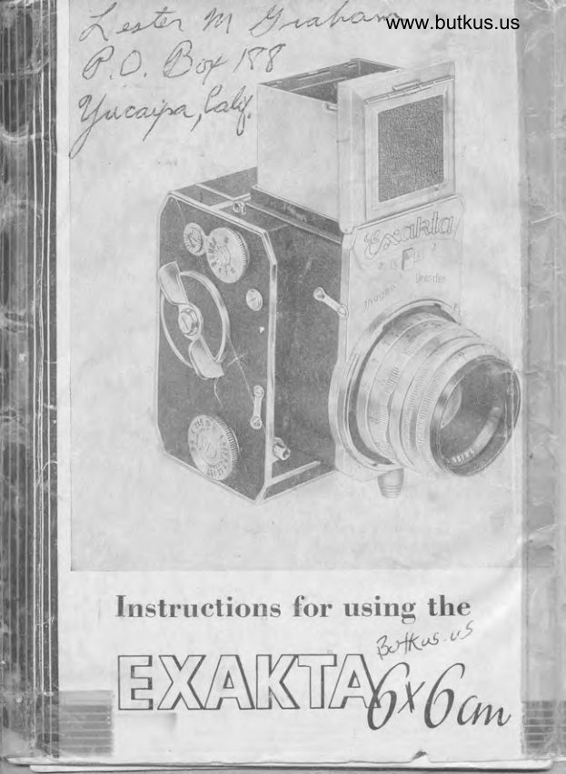
Exakta 6x6 vertical shutter User manual
User manual for Exakta 6x6 vertical shutter. 20 pages in English. Read the original PDF, download or print a copy without registration.
20 pagesEnglish2.3 MB PDF
Loading your manual…Open PDF directly
Document details
- Brand
- Exakta
- Model / document
- Exakta 6x6 vertical shutter
- Document type
- User manual
- Language
- English
- Pages
- 20
- File size
- 2.3 MB
- Category
- Film cameras
- Document date
- Not specified in catalog
Search available document text
Find a term, then jump to its page in the original PDF. Image-only pages may not be searchable; check the PDF for exact wording and diagrams.
Page 6 · Read text
fl                               www.butkus.us
{
      '14 :  Focusing ring with distonce scole
    15 :  Diophrogm presetting ring
    16 :  Diophrogm scole ring
     17 :  Lens
     t8 :  Knob for fostening lens
    19 :  Flosh-connecting nipple (DlN 19003)
    20 -  Adjusting disk for flosh connection    21 :  Tripod socket on side of comero
    22 :  Comero support
    23 :  Shutter releose knob
    24 :  Speed-setting knob for 1/roth s6c. to 12 secs., ond
              1/5th sec. to 6 secs. with self-releose (speed-regu-
             loting mechonism)
    25 :  Locking lever for shutter releose
    26 :  Reverse knob for exposure counter
    27 :  Winding disk                                                                                               .
    28 :  Speed-setting knob for 1/zsth to 1/1s0oth sec.,
        TondB
    29 :  Exposure counter
    30 :  Comero bock
    31 :  Loc*ing lever for comero bock
    32 :  Blonk plote for film notes

                                                                                                                                                                                                                                                                                                                                                                                                                                                                                                                                                                                                                                                               I    33 :  Extinguisher for blonk plote (32)
    34 :  Window for film-wind indicotor
    35 :  Film-key
    36 :  Feeler device for film leoder
   37 :  Film pressure plote
    38 :  Lorge film-sliding roller
    39 :  Lower film chomber
   40 :  Flop for lower film chomber
    41 :  Driving mechonism (upper film chomber)
    42 :  Upper film chomber
   43 = Rotchet wheel   44 :  Film gote with focol-plone shutter
                                                                         illFlt,
View original page 6Page 8 · Read text
www.butkus.us

Before inserting the Jirst_film, you must become perfectly
fomilior with your EXAKTA 6x6 ond leorn exoctly how to
hondle it. This is why the instruktions for inseriing ond       1
chonging the film hove been left to the lost.
                                                        .4-!-{
Removing ond ottoching the cqmerq bqck    ,_fAii
To unlock the comero bock (30), the lever (31) must be swung
olong the surfoce of,the comero body, clockrivise, holf o rototion
upwords,  i. e. in the\rpirection of the lighthood (l). push the
comero bock (30) obo'rrt 3 to 4 mm. to the left (looking ot the
bock of the comero) ond.toke it'off. - When reploiing thecomero bock, toke the comerg,lhto your left hond, ihe cornero
bock into your right hond        ttoch the bock so os to leove
o spoce of not more thoru3 to E mm between the projecting
porrport oTof rnethe comerocomerg bgdybgdy onctond th€'\   rrght-hondright-hond edgeedge ofof thethecomero bock, os in Fig/4. Ploce the hck in on ongulor position
to the comero oncj,,",fet the bottom edge of the bock exoctly
into the groove of the comero body. Now fold the upper
port of the bock ogoinst the comero body ond push  it


                                                      Fig, 4
View original page 8Page 9 · Read text
3 to 4'irm tb the right, until it st6ps. Swing the'locking lever (31)
         of the comero bock holf o rototion onti-clockwise downwords
          in the direction of the comero bose. Comero body ond comero
         bock ore now firmly connected ogoin.
                                                                                                                                                                                        -t       Opening ond closing the lighthood  ,
           Tilt the locking lever (7) towords the comero bock: the light-
        hood (1) springs open. - When closing the lighthood, turn in        the flops one ofter the other, os morked by the numbers 1,2It,  ond 3: first the flop with the eyepiece, then the right-hond
       ond ofter this the left-hond llop, ond lostly, the lighthood copL        which will click in oudibly.
        Shutter ond filmtronsport                                                                                                 .
         ore coupled (no inodvertent double exposures, ond no blonks !):
        the shutter is releosed by piessure on the shutter releose
       knob (23), shutter wind ond film tronsport ore octuoted by
       meons of winding disk (27).
                                                     toke hold    vi@                    bhsl!gr-!g!-wog!d -gd,      oitnffiingmediskholf
      o rototion clockwise until  it stops, ond let it run bock. In resting
          position, the red dot of the winding disk (27) hos to be ot
        upper left. Only in this position con the shutter be releosed.
        Releosing is impossible ot ony between stops. lf o number  is
          visible in the exposure counter (29), the winding disk (27)
        connot be rototed os long os the shutter is wound up. With
       the red F in the exposure counter (this oppeors ofter the
       number 12), the shutter releose is locked, but the winding
         disk (27) con be turned (importont for film tronsport without
         shutter winding, ot the beginning ond end of eoch film). To
        set exposure counter on the number 1 in ploce of the red F
         (or the numbers 2to12): push the reverse knob (26) upwords
         in the direction of the lighthood (1).
       The shutter
         Inston#exposures ol rf 25th to 1/166sth sec.: Lift the speed-setting
        knob (28) before or ofter winding the shutter, turn the knob
           until the desired speed stonds ogoinst the morking dot in the
        center ond let the knob (28) jump bock. The knob (28) moy
       be turned in either direction, however, there is no tronsition
        between T ond 1/12th sec. The numbers indicote froctions of
       o second, e. g. 25 :  r/2bth sec.
View original page 9Page 10 · Read text
www.butkus.us

fime exposures of ony desired        Set the knob (28) on T
:lB-,'rT=
                                 (23) is reloxed.
Automotic speed regulotion lrom                                                                                  1 f 13th sec. to 12 secs. (immediote
running down of the shutter):                     Set the
knob (28) on T or B. T
     se os for
                         ). Lift the                the
rotote it unti      desired  block number stonds ogoinst the
morking dot on the middle  disk, ond then let the outer ring
jump bock.
Exposures with self-releose (deloyed action)i
o) Shutter speeds from 1/sth sec. te 6secs.: Set the shutter
   os described just before, but odjust the knob (24) to the
   desired red speed number.
b) Shutter speeds from 1/25th to 1/roooth sec.: Set the knob (28)
   on the desired speed number, e. g. 1/166th sec., but not on
   T or B. Lift ond turn the outer ring of knob (24) os described
   before ond set it on ony one of the red numbers.
In connection with knob (2a), the btock numhe+s e^n
immediote.       -----;1-----.. exposure, whereosr      the red numbers indicote self-releose (oetoyeo ocilonI:
13 seconds exoire before the shutter opens.
The releose knob (23) is designed to toke o coble releose.
A locking device prevents unintentionol octuoting of the shutter:
By holf o rototion of the locking lever (25) clockwise upwords
in the direction of the lighthood (1), the releose knob (23)
is bolted.
The lens ond its odjustment
The lens (17) is interchongeoble: Push the knob (18) in the
direction of the comero bock, turn the lens to the left(looking
otthe comero front) untilthe red dots 12o ond 12b (Fig.5) stond
ogoinst eoch other. Lift the lens off the comero front. - Wheninstolling the lens, first ploce it on the comero so os to moke
the red dots meet ond then turn it to the right until  it clicks in.

4
View original page 10Page 11 · Read text
Focusing is performed by rototing the focusing ring (14) with
distonce scole. To set the diophrogm, turn the diophrogm
ring (16). (The smoll numbers2,8l3,5: lorge operture :  short
exposure, less depth of field, the lorge numbers 22116 :  smoll
operture: longer exposure, greoter depth of field). Detoils
ore given on the depth-of-tield scole (13): To the left ond
right of the focusing mork is the desired diophrogm number,
opposite which is indicoted the ronge of distonce within which
the exposure will be sufficiently shorp.
Lenses with diophrogm presetting device hove on odjustoble
stop ring for the diophrogm ring, On most lenses, the
pre-setting ring (15) behind the diophrogm scole hos to be
pushed bock towords the comero (Fig, 5), whereupon the dio-
phrogm ring (16) must be rototed until the operture (:dio-
phrogm number) with which the exposure is to be mode, stonds
ogoinst the red morking dot. Now let the presetting ring (15)
spring bock into its originol position. Focusing con be performed
with the lens ot full operture ond, immediotely before releosing
the shutter, without chonging the position of the comero, the
diophrogm ring (16) is turned bock to the "pre-set stop",                                                                -With other lenses, there moy be slight deviotions concerning
the employment of the "diophrogm pressetting device",


                              :-16


   Fig. 5
View original page 11Page 12 · Read text
www.butkus.us

How to use the lighthood
The ground-gloss imoge is enlorged by the interchongeoble
                                                                                                                                                                                                                                       I                                                                                                                                                                        I ig hthood (1 )' Add itionog ro, n'd-g loss mo g n if ieiu nde rneoth the
Jnlorg"tent  is goined by the mognifying lens (4)' Fig'2: Push
the kiob (6) downwords in the direction of the orrow' With
the mognifying lens (4) in working position, push the two side
flops of- the li!hthood slightly inword, using light pressure of
thumb ond index finger, cousing the flops to snop into the
ponel (5) of the mojnifying lens (protection ogoinst outside
iignt). Wh"n using the mognifying lens (4), hold the comero
close to your eYe!
To fold the mognifying lens (4) bock into its originol position,
roise the mouniof theJens, thereby disconnecting the lighthood
flops from the lens ponel ond push the lens ponel into the
lighthood until it clicks in.


                                                          Fis. 6
View original page 12Page 13 · Read text
The lighthood moy olso be converted into o direct-vision frome
         finder: bring the mognifying lens (4) into working position
       ond open up the hinged !ighthood finder flop (8). The squore
        opening in the reor flop (3) of the lighthood serves os eye-
         piece. - Subjects in very ropid horizontol movement should be
        token with the comero held in the horizontol position (Fig. 6).
       The lighthood is interchongeoble (extro focusing systems ore
 I       in preporotion): Close down the lighthood before removing
1dI            it from the comero. Press down the knob (10), liftthe lighthood
        obove the knob (10) ond toke  it corefully out of the beorings.
      When replocing the lighthood, first slip it into the beorings
        from the bock of lhe comero (two pins in the lighthood  fit
         into two holes in the frome of the beorings) ond then fosten
                it ot the front obove the knob (10). (The lotch snops in oudibly).
       To exchonge the mognifying lens (ground-gloss mognifier),
        toke off the lighthood. Push up the locking lever (11) os for os


            Fig.7
View original page 13Page 14 · Read text
www.butkus.us

it will go (Flg.7), tilt the comero corefully, ot.the some time
tokinq'holi 6f tire mognifying lens in the lighthood Jrone' To
inrertln" ground-glosJmognifier,  or o speciol mognifying lens,
push up tfle lockiig lever (11), ploce the lens (its flot surfoce
iowords the comerd mirror), cut-in groove first, into the comero
i-,  tn" reor ond let it slide intolhe frome ot the front. Not
until this hos been occomplished, moy the locking lever (11)
ipring bock into its originoi position, Toke core not to touch
if;" jrouna-gloss surfJce oi the lenses with your fingers!
Looding the film
Negotive moteriol: Roll film 6x9cm for 12 exposures.6x6cm
(2ti+*2rl+").While the tilm is being looded, the red F must
 Le'uitiUie in the counting mechonism (29)' lf necessory, turn
the knurled knob on the counting disk until the F oppeors.
Remove the comero bock, os described in section 1'
 Inserting on empty film spool into the upper iilm chomber:
Turn the film key'no(35) quorter of o rototion to the right, ond the red dots will    longer be opposite eoch other. Drow out
 ihe film key (35) until it-stops. Pioce on 9mp!y film spoolwith
 the long riit'on the left,  i. e. on the side where the rotchet
 wheel 1iS1 is, on to the driving mechonism (41).in the.u.pper
 iif. ai*b"i  (qz), On the rishl-hond side (film-key.side) the
 ;;;"i  must be loid into the-film chomber (42) ond the film
 llv igSl pushed in, so thot the peg of the film key co.tched tliJ iornd hole in ihe spool. Now turn the film key (35) with                                                             red                                                    the                                        ond                                                              left,                quorter                                   to the                              rototion                   o                         of       oressure slioht                  'below)                                                           spool                                                           film                                    The                                       emptv                                 ogoin.                          meet                              will           ond l;i;i"b";e
, is held tight on both sides.
 Inserting the unexposed film into the lower iilm chomber:
 Open the lower film chomber (39). Unfold the flop (40)' -Smpletety           remove the gumstrip from the film. Unroll obout
 1O|' (4")'of the protecfive poper' but hold the film tightto
 ovoid penetrotion bt tignt. Put the roll film into the lower film
 .horU!t, with the colo'red, printed surfoce inword, so thot the                                                             film-sliding                                 the lo_rge                          oround                   drown        leoder              be           con fop",                                                     the empty                                                (37) to                                           plote                              film pressure                      the               ocross          ond  i"ti"i (Sg)
 ,p"d iFig.8). The block surfoce of the protective poper must be
  I
View original page 14
Page 15 · Read text
visiblel Hold the protective poper tight' Close the lower film
chomber (39). Introduce the pointed leoder of the protective
poper into the long slit of the empty spool (the slit must be
completely filled ouiwith the poper). Turn the rotchet wheel(43)
in the direction of the film pressure plote (37),  i. e' towords
the protective poper, thereby rolling up the poper leoder.until
the spool core is covered by one loyer of poper. Turn -down
the poper point projecting from the spool slit with your finger.
The poper strip must now lie perfectly flot ond tight on the
f ilm pressure plote (37), block surfoce upwords    !

Whot to do before toking your picture
Attoch comero bock os described. Toke core thot the bock is
ottoched from the for right os shown in Fig. 4 (spoce between
comero bock ond projecting port of the comero body not more
thon 3 to 4 mm), otherwise protective poper might be domoged   !
Turn the winding disk (27) seven times from its resting point
to the stop, letting  it run bock eoch time. Before this performonce,


   Fig. B
View original page 15
Page 16 · Read text
www.butkus.us

 the red F must be visible in the exposure counter! After the
 seven rototions, moke only short movements with the winding
 disk (27), closely observing the progress of the film ond the
 window for film-wind indicotor (3a). As soon os the film leoder
 reoches the feeler device (36), the light signol in the
window (34) will jump obout 2 to 3 mm to the right (Fig. 9),
                               whereupon the red
                               dot of the windino
                                      disk (27) hos to bE
                                wound only for obout
                                       II5    mm more,
                                  with noticeoble
                                   drought of the film.
                            The first section of
                                           film is now in the film
                                           gote. Push the reverse
                            knob (26) for  the
                                    counting mechonism
                              Fig. 9       upwords in the direc-
                                            tion of the lighrhood,
ond the exposure counter (29) is set on No. 1. With the
locking mechonism out of oction, the comero is reody for the
exposure. Moke no odjustments on the counting mechonism
during the l2exposures, otherwise film tronsport will be uneven.
The blonk plote (32) is designed for moking notes concerning
the kind of negotive moteriol in the comero, e. g. DLC :  doyl
light color film, or ISS 21 /10, etc. Only use blunt writing
moteriol (o motch or something similor), ond no scrotching
points. To extinguish the writing, turn the knob (33).
Moking the exposure
      1) Open the lighthood
      2) Set the shutter speed (exposure time)
      3) Focus ond view the reflex imoge
      4) Stop down the lens
      5) Releose the shutter
      6) Wind the shutter ond film tronsport (simultonecusly
         setting the mirror ond counting mechonism) by
           turning the winding disk (27)
          without further observing the signol in window (34).

10
View original page 16Page 17 · Read text
The performonces No. 2 to 4 con, if desired, be corried out rn
 different succession. All the performonces ore repeoted until,
 ofter the 12th exposure, the red F oppeors in the exposure
 counter (29).
 Exposures ot l1zl,th sec. ond shorter con be mode   f rom your hond,
 without o frlF6?llTor longer exposures, o tripod should be
 used, inffoct it moy be necessory. There ore two tripod sockets,
one in the bose plote ond one in the right-hond side of the
 comero, for fitting  it either in the verticol or horizontol position
 (21), os seen from the front.

Chonging the film
After the rcd F oppeors in the exposure counter (29), octuote
the winding disk (27) repeotedly until the light signol in the
window (34) recedes to the left ond winding becomes eosier.
Remove the comero bock, turn the film key (35) quorter of o
rototion to the right ond pull  it out. The exposed film con now
eosily by token out of the comero ond the gumstrip posted
down to ovoid unrolling. - Ploce the empty spool out of thelower film chomber (39) into the upper film chomber (42) os
described before.

Ffoshlight connection
is designe d  for rggulor floshes (Vokublitjl6nd flosh tubes
(electronic floshesJ. In both coses, the cobFtbfa  is connected
to the contoct ni'pple (19). The ignition of flosh tubes being
procticolly without deloy, the odjusting disk (20) is set on 0
by turning the milled control knob in the direction of the orrow
(the 0 is underneoth the red dot). In connection with flosh
                                                   ,<,5ii,'l:[liih:occording to o speciol toble still in preporotion in which ore
contoined numbers referring to the flosh bulb ond to the
corresponding shutter speed (these numbers ore only reference
volues ond not milliseconds morking the ignition deloy). Never
turn the odjustment disk (20) ogoinst ihe direction of the
grrow. This might leod to on unintended contoct.


                                                                        11
View original page 17Page 20 · Read text
www.butkus.us
    NOTICE CORRECTION                     I
                                                                                   1
                                                                                            Ia
THIS REPLACES INSTRUCTIONS ON PAGE 2
    FIGURE 4 FOR REPLACING BACK.
  Affer the bqck is loqded, in order to replace
the back on the camera body, hang the back by
aligning the two catches on the left side of back
on to ihe two pins of the body gently. (See Fig. l.)
Then press the back down on the rght side2 and
at the same iime exert pressure on the left side
inwardlyr to make sure the back is aligned correctly.
(See Fie. 2)
 When replocing the bqck be careful not to
move the locking lever (#31) accidenfly as this will
prevent ihe back from closing properly.
    lf the above mefhod is not used it may tend to
lear the paper backing and film. When advancing
{ilm by winding be certain the winding disc l#27l'
is wound fully clockwise and firmly againsi the stop.
Only ihen will the winding disc automatically return
lo its original position. Do noi release shuifer unfil                                                           ;winding disc is in original posiiion.
                                                            t
View original page 20From the M. Butkus archive. Original publisher and archive notices are retained.
Check the model and edition against your equipment.
PDF verified 2026-10-10.