Film cameras
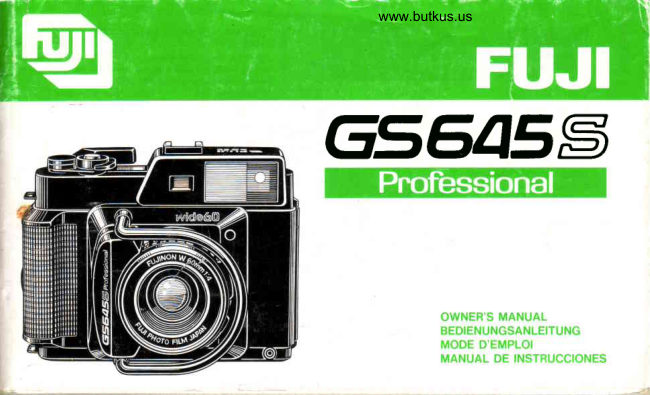
Fujifilm Fuji GS645S User manual
User manual for Fujifilm Fuji GS645S. 62 pages. Read the original PDF, download or print a copy without registration.
62 pagesOriginal document5.6 MB PDF
Loading your manual…Open PDF directly
Document details
- Brand
- Fujifilm
- Model / document
- Fujifilm Fuji GS645S
- Document type
- User manual
- Language
- Check the original document
- Pages
- 62
- File size
- 5.6 MB
- Category
- Film cameras
- Document date
- Not specified in catalog
Search available document text
Find a term, then jump to its page in the original PDF. Image-only pages may not be searchable; check the PDF for exact wording and diagrams.
Page 10 · Read text
www.butkus.us
m       EV 4 - 18 coupled range with ISO/ASA 10O film; GPD  HOW TO USE
            ohotocell (incorporated in viewfinder); two LR44 1'5V
           alkaline-manganese batteries; pressing the  shutter   READYINGTHE CAMERA
                                on power switch'zotraI         release halfway down turns
        o Film Advance
           Film advance lever on camera top, 184" winding angle'      1. Attaching the shoulder straP
            28' stand off, self-cocking shutter, 12O/22Oroll film         (Fig.1) A. Buckle
            switchover.                                                        B. HooP
        o Others                                           Pass one end of the strap through the camera's strap lug'
          Lens protector;palm grip with tripod socket; switchable    pass it back through the hoop and buckle and adiust the
            pressure plate for 12O and 22O roll film with 12O' 22O     strap length with the buckle' Do the same with the other
             indicator in camera back.                            end of the straP.
        o Dimensions                                         a Move the hoop when you pass the strap end through it'
           1 4 7 m m W x 1 1 4 m m H X 9 o m m D                    The strap will pass throughit easier if you do'
         o Weight
          766 g. (without batteries)'                                      2. Attaching the viewfinder eyepiece (Fig' 2)
         o Accessories                                    The vieMinder eyepiece is screwed into the eyepiece
            Soft case, shoulder straP, lens hood'                       socket.
          Notice:                                                o The viewfinder eyepiece that comes with your camera
          Specificationsare subject to change without notice'                 is designedfor people with normaleyesight'lf you can-
                                                                      not see clearly throughit, use an eyepiecethat fits your
                                                                      eyesight.
                                                                                                                            lf you are nearsighted,use an eyepiece with a minus
                                                                          diopter,and if you are farsighted,use one with a plus
                                                                        dioPter.
                                                              o The eyepiece socket of your GS645S has a 19mm
                                                                 diameterand a O.75mm-pitchscrew thread' lt will take
                                                             any commerciallyavailablediopter-adjustableeyepiece'
View original page 10Page 11 · Read text
rightanglefinder, etc.                                                   4.  Putting on the  filter and lens hood
    Fuji does not supply these accessories.                           (Fig. 6)  A. Lens hood
                                                                                 B. Filter
 3. Loadlng the batteries (FiS.g)                             To mount the  filter or the lens hood, just screw  it into the
With a coin, loosen the battery compartment cover screw       front of the lens banel. (Fig. 6)
and remove the battery compartmentcover. Insert the two       o  Filters are commercially  available. Be sure to ask  for
 batteries that come with your camera in the battery com-       49mm filters.
 partment,plus and minus ends correctly as illustratedin      o  Use the lens hood that comes with your camera.
the battery compartment,then replace the cover and tight-
en the screw. (Figs.3. 4, & 5.)                                          5. Pufting on the lens cap
 o Be sure to use either two LR44 alkaline-manoaneseor          (Fig 7)  A.  Lens cap
   two SR44 silver oxide batteries.                             o  The lens cap  is fitted into the lens hood. Just press in
 o The battery power required to operate your camera's         the two  projections on the  lens cap,  fit the cap  into
   exposuresystemcorrectlyis 2.4volts or more.lf the LEDs         the lens hood, then release the projections. That's all.
    in the viewfinderturn on, the batteriesare producingsuf-        To prevent accumulating  dust and debris on the lens
,   ficient voltage,but if they do not turn on, you'll have to          glags, make  it a habit to put the lens cap on as soon
   change the batteries.                                         as you are through taking pictures. (Fig. 7)
 o Do not use an alkaline-manganesewith a silver oxide,         Tiny abrasion marks  will develop on the lens surface
   or an old with a new battery because such pa.iringcan                   if you are not careful when you wipe  off dust and debris
   result in battery leakage or ruptured battery casing and         from   it with a  silicon  cloth  or other similar material.
   cause irreparabledamageto your camera.                       Caution  is required because  abrasion  rnarks and con-
Caution:                                                         taminants on the lens glass will reduce the sharpness
 o The batteries can be extremely dangerous if swallowed.           of the lens by an appreciable amount.
  Do not leave them within reach of little children.             a  Your camera is designed for taking pictures with the lens
 o Discard used batteries into a used battery collection         hood on. The lens cap  is therefore made for fitting  into
   box, if any, at your photo dealer.                                  the lens hood.
                                                         Be careful when you clip the lens cap directly into the
                                                                          lens barrel front because   it can easilv  fall off.
View original page 11Page 12 · Read text
www.butkus.us                                                                                  "120"m                                                                                                        to the center peg, and  if you are using 220             6. Using the soft case                                     marked
           o  The camera  is placed  in the  soft case  with the lens       film, fit the other hole to the center peg.
            hood on, and the case  is closed with  its zip and stick     The  pressure plate  indicator  in the camera back  (below   zotrU)  I             fasteners.  (Fig. 8)                                             the  film reminder  slot)  will show you which  side  of the
         Use  it when  carrying the camera about  or when  putting   it     pressure plate you have set. (Figs.11, 12)
                                                                                     Selector)         away because  it is a good protection against dust, abrasion,     (Film                                                                                                                                                                  f ilm ...'..............." "'30 exposur es                                                        22O r oll            nicks, and dents.                                                              120 r oll film '.....       """"15  exposur es                     /
       LOADING THE FILM                                  120 half-length roll film""""'7   exposures
                                                                         a Be sure to move the pressure  plate to the correct  side
           1. Opening the camera back (Fig. 9)                           because  the  film  will  not move  into the  exact  focal
        To ooen the camera back, erect the camera back lock        plane  if you don't. (120 roll film is attached to an opaque
        and oress it down toward the camera bottom.                    backing paper over  its entire length but such paper  is
        To close  it, keep the lock erect, press the camera back       used only on the ends  of 22O roll film as leader. The
         againstthe body, then snap the lock down (Fig.9).                thickness  of the backing paper causes a  shift  in the
         o The camera back won't close unless the camera back         position of the focal plane and the pressure plate adjusts
             lock is erect.                                                             for  this  difference  while  keeping  the  film  flat on  the
                                                                                     focal olane at one and the same time).
           2, 12Oi22O roll film switchover (Fig.10)                       a Your film box says your',|20 roll will yield 16 exposures,
         o Be sure to set the PressurePlate and Film Selector        but this  is merely an indication that the film length  is
               for the type of roll film (120or 22Olyou are using.             capable of accomodating  that  number  of  6  x  4.5cm
          (Film  Selector)                                                frames. On account of improved film flatness and clipping
                  lf you are using 120 film, move the film selector so that         of the film end during processing, however, there  is a                              "120"                               and if you are using 220 film'       chance of losing the last frame. Your camera is therefore                  it uncoversthe number
                                            "220" (Fig. 1O).           quoted as a 1S-exposure camera when  using 120  roll        move it so that it uncoversthe number
         (Pressure Plate)                                                        film.
                  lf you are using 120 film, press down the pressureplate     o   lf you are using 120 half- length  rolls of Fujicolor Pro-
          with your fingers, slide  it and  fit the hole on the side        fessional Type S and Type  L  films, be sure to move
. 1 4
View original page 12Page 13 · Read text
4'
   the pressure plate to the 120 side. You can take 7 frames       start mark on the paper leader lines up with the arrow near                                                                                                                      ra   but the  film advance  lever will not become  free even      the top side center of the film channel(Fig.15),then close
    after you expose the 8th frame.                            the camera back.                                                                                                                                                                                   (5z                                                                                                                                                                                                         IIJ a  After exposing 7 frames, wind the film and press down      o Remember, the camera back won't close unless the
   the shutter release. Repeat until you wind up the entire       camera back lock is erect.
    roll and the exposure counter stops. Be sure to keep an          .. Avoiding film slack
   eye on the exposure counter while taking pictures.          While winding the paper leaderon the take-up spool, press
                                                                                                         it down lightly against the camera body with your finger
3. Loading the take-up spool and film                     and wind it firmly on the spool.
   (Fig.13)   A.  Press                                To preventthe film from slackening,keep it taut with the
O Pop out the spool knobs  by pressing  in the spool knob       film advance lever until you close the camera back.
   release buttons (small red buttons  in the supply and       (Start mark positioning with 22O roll film)
   take-up sides). (Fig. 13)                                                      r   lf you are using 22O film, be sure to set the NORMAL
@ Take out the empty spool, fit  it into the take-up chamber      LEAD mark (solid line with arrows)on the film opposite   (located on the same side as the film advance  lever),                                                               the start mark on the camera. Do not use the LONG
   then press in the take-up spool knob.                   LEAD mark (dotted line).
O Load the film in the film chamber (located on the same          (Fig. 16) A. Set this mark.   side as the viewfinder eyepiece), then press in the film
   loading knob (Fig.14).                                                                    5. Winding the film and positioningit for the first shot o The take-up  spool and  film  roll can be loaded easier                                                              After loading the film, wind the film advance lever as far   by fitting in the top (camera top) side first.                                                     as  it will go five or six times. The exposurecounter will                                                                      "S"                                                         switch from                                                                                  to "1" (first frame)and the shutterwill cock4. Positioning the film  start mark  (Fig.15)                                                       by itself. (Fig. 17)Pull out  the  film  leader paper, pass   it through the  film                                                       o Tear off the top of your film box and insert it in the filmchannel,  insert the  tip  into the  slot of the take-up  spool,                                                        reminder slot in the camera back. lt will remind youthen wind the paper leader around the spool with the film                                                     which film you are using(Fig.18).advance  lever.
Stop winding the  film advance  lever as soon as the film
View original page 13Page 14 · Read text
www.butkus.us
                   ADJUST]NGTHE CAMERA         SETTINGAND
                                                                                                                                                                                                                                                                         'r     I 600                                                                                       25       50        J00      200      400      800                   ETC.        CONTROLS,
                1. Unlockingthe shutter release                                      32 40    64 80    125 160   250 320   500 640   10001280
                (Fig.19) Locked
                  (Fig. 20)  Unlocked
            To unlock the shutter release to take pictures,push the     3. Setting the shutter speed and aperture rings
                shutter release lock to the front. To lock  it' push it back        (Ftg. 221  A. APerturering
              sb tnat it uncovers the letter                                              "L" (Lock) (Figs.19, 2O).                      B. ShuttersPeed ring
                                                                                C. Setting mark (index mark)
                 2. Setting the film speed selector (Fig. 21)                   Shutter speed and aperture are set by turning the shutter
                  (Fig. 21) A. Film speed selector                     speed and aperturerings.Use the small knobs on the rings
            The underside of the aperture ring is engraved with film     to turn them.
            speeds in ISO (ASA)numbers.                           o  Both the shutter speed and apedure rings are provided
            To set the camera for the speed of the film you are using,        with click stops at each step and are set to the red
                turn the film speed selector (thin ring located between the      marks on the lens barrel(Fig' 22).
               shutter speed and aperture rings) and set the red spot on      You cannot use intermediateshutter speeds.
               the selector opposite the number that matches the speed
                of the film in the camera.(To turn the film speed selector,    4. Focusing the lens
                insert your fingernailin the dent providedon the ring and        (Fig. 23)  A.  Bright frame
               turn it while holding the aperlurering still to preventboth                B. Double-imagefocusing sPot
                rings from moving together.)(Fig. 21)                      Look through the viewfinder eyepiece, center your subject
              o The film speed selectorhas click-stopsettingsfor ISO/      in the viewfinder,and turn the distancering until the doubleI            ASA 25 to 1600in 1/3-stepincrements.The scale shown    image in the yellow double-imagefocusing spot correctly
               below representsthe numbersand white dots inscribed    coincides(Fig. 23).l   t               on the film speed selector.
View original page 14Page 15 · Read text
'1
o Be sure to align your eye with the center of the view-           will make up for the slightlynearerpoint on which you'll        ro
   finder eyepiece because the double-image focusing        have to focus.
   spot will move off center of the viewfinder and orevent   precisefocusing if you don't.                                                                                                                    ozLlj
5. Composing your picture
   (Ftg.zal  A. Moving top and left frame lines
Composeyour picturewithin the brightframe.As you focus,
the top and left sides of the brightframe will automatically.
move to correct for parallax. There is hardly any parallax,
however,and you'll get properlycentered pictures because
the field of view at nearest focusing distance (1 meter) is
 9'lo/oand 9Oo/oat infinity (co).
6. Using the depth of field table (Fig. 25)
Depth of field  is the zone of sharpness in front of and
behindthe point on which the lens is focused and it varies
with the lens focal length, aperture and shooting distance.
Your camera is provided with a depth of field scale on the
lens top on both sides of the lens setting mark, but for
more detailed readings,refer to the accompanyingdepth of
field table (FiS. 25).
Example: lf you are shooting with your camera's 60mm
          lens from a distance of 5 meterswith an aperture
           of f/8, everythingbetween 3.29 and 10.67meters
         from the camerawill come into sharp focus.
o To take infrared pictures, measure the distance of the
  subject with the focusing ring and set that distance to
  the infraredmark (locatednext to the index mark).This
                                                                                 17
View original page 15Page 16 · Read text
i    www.butkus.us
m
zatr(n     DEPTH OF FIELD TABLE FOR1 YOUR EBC1.2FUJINONW1 . 6omm5     F4 LENS2         3         Permissible5        circle1of0 confusion:oo0.05mm-   );----C;ug
                    4          0.96-1.05 1.14-1.27  1.40-1.61  1.82-2.21 2.60-3.54  3.96-6.79  6.51-21.81  18.25- co
                 5.6        0.95-1.07  1.12-1.30  1.37-1.66  1.76*2.32 2.47 -3.83  3.65-7.99   5.70-  oo    12.94-cn
                 8         0.93-1.10  1.09-1.35  1.32-1.74 1.68-2.49 2.30-4.33 3.29-10.67 4.85  -  oo     9.19- oo
                   1 1        0.90-1.14  1.O5-1.42  1.26-1.87 1.57-2.77 2.11-5.33  2.85-20.47 4.01 -  oo      6.53-  co
                1 6         0.86-1.21 1.00- 1.53 1 . 1 8- 2 . 1 0  1.45-3.32 1.88*7.99  2.47 -  s:,    3.23 - oo      4.66- oo
              22         0.82-1.33  0.93-1.74 1.09-2.53  1.31-4.64 1.64-27.98 2.06 - co    2.54-  ut      3.33-  co

          7. Setting the aperture selector (FiS. 26)                        (a O LED on but + LED barely on: About 1/3 stop over.
       QSet the film speed selector, then set the shutter speed      (3) O and * LEDs on at the same time but O LED barely
             for the type of picture you are taking.                      on or just off: About 1 stop over.
       OUnlock the shutter release,look through the viewfinder     (4) Only + LED on: 1 stop or more over dependingon how
          and press the shutter release about halfway down to          far the aperture ring is turned.
           turn on the LEDs on the right hand side just outside of      (5) O LED on but - LED barelyon: About 1/3 stop under.
           the bright frame.                                          (6)0 and - LEDs on at the same time but O LED barely
           Next, turn the aperturering and adjust it so that you'll       on or just off: About 1 stop under.
          leave only the circularcenter LED on.                         (7) Only - LED on: 1 stop or more under dependingon how
              .i( Readingthe LEDs)  (Fig. 26)                                        far the aperture ring is turned.
          (1) Only O LED on: Correctexposure
18
View original page 16Page 17 · Read text
8. Checking the light angle                                1O. Taking long-exposure pictures (using the T button)        T                                                                                                                                                                          IYour camera is equipped with a GPD light-meteringphoto-         (Fis.29)  A. T(Time)button
cell  in the viewfinder. lt measures the  light which  is     To take long-exposurepictures,open the shutter by pressing                                                                                                                                           oz                                                                                                                                                                       IJJreflected by a semi-transparentmirror after  it enters the     down the T button (the shutter speed ring can be set
viewfinder'sobjective lens. lt  is highly effective against     anywhere).
diagonalbacklightingand does not reqLireexposurecom-     To close the shutter, press down the shutter release.
pensationwhen taking diagonally backlighted portraits,etc.      o The T button will not operate unless the shutter has
However,it must be shielded in directly backlightedand        been cocked (by winding the film advance lever).When
brightly top-lighted situations.                                    the shutter is cocked, the top of the T button will be
                                                                       level with the top edge of its socket.
9. Winding the film and pressing down the shutter release      o The top of the T button is kept level with the top of
   (Fig. 271  Vertical position                                                  its socket to prevent pressing it down inadvertently.
               "1" lf the number                      is showing in the exposure counter, the        The T button is activated by pressing it down. You can
shutter blades will open and close when you press in the        use the front end of your cable release if you wish (Fig.
shutter release.                                                          2el.
A single stroke of the film advance lever will wind the      Caution
required length of film, cock the shutter, and advance the           lf you turn the shutter speed ring while the shutter blades
exposurecounter at one and the same time.                  are open during time exposure,it will get stuck in the mid-
(Fig.28)  Horizontalposition                             way. Do not operate the shutter speed ring or self-timer
The main cause of fuzzy pictures is camera shake. Be      during time exposurebecause malfunctionmay result.
sure to hold the camera still and press the shutter release
gently down (Figs. 27, 281.                                   11. Using the self-timer
(Using a tripod)                                              (FiS.30) A. Self-timerlever
 lf you are shooting indoors or nighttime pictures with a     Push the self-timer lever all the way down then press down
shutter speed of 1/3O-secondor slower, use a tripod and a      the shutter release.The shutterwill trio in 8 or 9 seconds
cable release.                                                (Fie.3o).


                                                                                     19
View original page 17Page 18 · Read text
www.butkus.us
   m       12. Taking flash pictures (Fig.31)                                     of tension will tell you that the trailing end has left its spool
                 Small, clip-on type flashes are clipped into the accessory      and that winding has been completed.   lt  will take about             zotr       shoe on the camera toP (Fig. 31)                                      five  strokes  of  the  film advance  lever to wind  the  film
      Q
                I         Your camera has an x-contact  (Fig' 32)'  that  is, electronic       completely.
                 flashes will synchronize with  all shutter speeds.                  Next. ooen the camera  back, take  out the exposed  roll of
                 o   lf you are using a flash bulb, use an M-class bulb with       film and seal the end to prevent the roll from unwinding'
                   a shutter speed of 1/3O-second or slower.  lf the shutter      o The empty  spool  is transferred  to the take-up  side  for
                 speed  is 1/60-second or faster, the flash will discharge         taking up the next roll of film.
                    but  it will not synchronize properly and a large part of
                   the light will be lost.                    CAMERACAREAND MAINTENANCE
                Note:
                Your camera  requires a flash  with a 50'  coverage  for the       1. Checking the camera before shooting
                 longer picture dimension and a 39' coverage for the shorter     Beforeloadingfilm in the camera,make it a habitto perform
                  picture dimension.  lf you are using a small size flash, be      the followingchecks.
                sure   it  is a  wide-panel  unit  that  is compatible  with an            I  Film advance unit
                                 f :35mm  on a 35mm format. But  if  it has a different vertical       Open the camera back and, while watching the take-up
               and horizontal covering angle, the picture frame must be         spool, wind the film advance lever to make sure the
                 positioned  to   fit  into  that  angle, otherwise  light  fall  off         lever and the spool holderare operatingsmoothly.
                along the edges will result. (Fig. 33)                                     @ Camera back interior
                            B.  Flash covering angle (flashes with  different       on the camera back and two on the body) to make  l               (Fig. 33)   A.  Light fall off                              Open the camera back and turn the three rollers (one
                                   vertical and horizontal covering angles)             sure they are properlyattached and are working smooth-
                            C.  6  x 4.5cm  format  (50"  for  longer  and  39"            ly. Also, check the film pressurespringsin the take-up
                                     for shorter Picture dimensions)                   and supply chambers to make sure they are properly
                                                                           attached and can exert sufficient pressureon the film.
                  13. Unloading the film                                   €  snutter r               After you complate exposing a  roll of  film, wind   it up to       Check the various shutter speeds through the camera
                  the very end with the film advance lever. A sudden release        back. You can more or less tell whether the shutter is
    20t
View original page 18Page 19 · Read text
operating  at the  right speed  or not by the amount  of          with an air blower.                                                                                                                                                                                    rU'
           light  it passes through and by the sound  it makes.         @; Next, moisten a sheet of lens cleaning paper with a small
   @ Aperture                                                amount of Fuji lens cleaning fluid and wipe the lens gen-       Open  the camera  back and  turn the  aperture  ring  to             tly with  it in a circular motion. Always start from the cen-                     J(,zut
       make sure the aperture blades open and close smoothly.           ter then gradually move out to the edges.
      6  Flash synchronization                      @ Finally,  after   all  contaminants  have  been  removed,l
          Clip on the  flash, open the camera back, open up the         wipe  off the remaining lens cleaning  fluid with a dry
         aperture fully, set the shutter speed ring to the speed         sheet  of  lens  cleaning  paper. Again,  start from  the
        you want, then press down  the shutter release.   lf light          center in a circular motion then move out to the edges.
       comes  in through the lens, flash and shutter speed are      Caution:
          correctly synchronized.                                       Breathing a mist on the lens surface then wiping   it off with
   @ Exposure  indicators                                                silicon cloth or other similar material is the worst thing you
        Look through the  viewfinder,  press the shutter release      can do. Never do  it because this is one of the main causes
         about  halfway down,  then  turn the  shutter speed and       of scratches on camera lenses.
         aperture rings as  well as the  film speed  selector  to
       make sure the LEDs respond correctlv.                           3. Precautions
         Better still if you can use a place of fixed brightnessas          r  Always load and unload film in subdued light.
       a criterionfor checkingthe consistencyof the response.    o  In hot weather, do  not leave your camera  in a closed
     lmportant:                                                            car  or  in  moist  places  except  temporarily  for  a  very
    Camera trouble can cost you dearly both materially and         short time.
     otherwise.                                                    o Always  clean  your  camera  before  and  after  taking
                                                                              pictures. Clean the interior with an air blower, and wipe
      2. Cleaning the lens                                                          off exterior with silicon cloth.
    Scratches on the lens surface can reduce its sharonessfar      o Put your camera away where  it is cool, dry, and free of
    more than you would think. lf the contrast of your picture        dust.
    seems somehow insufficient and  it doesn't look crisp     o  Always  check  your camera  before  taking  pictures  to
    enough,the cause is usuallyscratcheson the lens surface.      make sure that all your pictures will turn out right.
       (t, First, blow off dust from the lens surface completely
                                                                                       21
View original page 19Page 20 · Read text
g
                                                             EINSTELLEN DER BEDIENUNGSELEMENTE   28
         Diese Anleitung enthalt alles, was Sie tiber die         1. Entriegeln des Auslosers                       28
          Bedienung und Pflege lhrer Fuji GS645S Professional          2. Einstellen des FilmempfindlichkeitswAhlers   28mc{@o        wissen m0ssen. Lesen Sie die Anleitung daher bitte         3. Einstellen von VerschluBzerten- und Biendenring 29
          aufmerksam durch.                                            4. Scharfeinstellung des Objektivs                 29
                                                                         5. Sucherfeld und Parallaxe                       29
                                                                         6. Gebrauch der Scharfentiefentabelle           29
                                                                              7. Wahl der gewunschten Blende                      31
      INHALTSVERZEICHNIS                                     8. Uberorufen des Lichtwinkels                        31
                                                                         9. Filmtransport und Betatigen des Auslosers             3.1
       BEZEICHNUNG DER TEILE                           23       lO. Langzeitbelichtung (Gebrauch des "T"-Knopfes)  32
       TECHNISCHE DATEN                                23       11. Gebrauch des Selbstausl6sers                32
       BEDIENUNG                                                     12. Blitzaufnahmen                              32
       VORBEREITUNGEN                                  24       13. Entnehmen des Films                          33
                1 . Anbringen des Tragriemens                         24     PFLEGE UND WARTUNG DEF KAMERA            33
          2. Anbringen des Sucherokulars                      24       1. Uberprufen der Kamera vor dem Fotografieren    33
         3. Einsetzen der Batterien                           25      2. Reinigen des Oblektivs                         34
         4. Aufsetzen von Filter und Gegenlichtblende          25      3. Vorsichtshinweise                            34
         5. Aufsetzen des Objektivdeckels                     25
         6. Gebrauch der Kameratasche                       26
        EINLEGEN DES FILMS                              26
          1. Offnen der Kameraruckwand                      zo
          2. Umschalten zwischen 12Oer- und 220er-Rollfilm     26
          3. Einlegen der Aufwickelspule und des Films          27
          4. Ausrichten der Filmstartmarke                      27
          5. Vorspulen des Films auf die richtige Stellung   fur
             die erste Aufnahme                                28

22
View original page 20Page 21 · Read text
BEZEICHNUNG DER TEILE                                              Q7,l Filmstartmarke                                                EO
                                                                            €s) nolle f0r Erfassung der FilmaufwickellAnge
 il-) Objektivschutz                                    Qd Filmandruckplatte (2,' Einstellmarke                                     @0 Spulen-Rndruckfeder                                                                                                                           @F:ITo
€)- Verschlu Bzeitenring                                                     f1l Spulenknopf-Entriegel  ung
(f Blendenring                                                          @2) Aufwickelspule
l5) Scharfei nstel  lri ng
G-l Aufsteckschuh                              TECHNISCHE DATEN(f "T"-Knopf (fur Zeitaufnahme)
@ Auslosersperre                            o Kameratyp
(0 Ausloser                                       6 X 4.5-cm-Format, mit Entfernungsmesser.
(1, Fi lmtransporthebel                          o Film
Ii,r BildzAhlwerk                                                           Rollfilm 120 (15 Aufnahmen) und 22O (30 Aufnahmen).
(| Aufwickelspulenknopf                        o Objektiv
[tl Batteriefachdeckelschraube                        EBC Fujinon W 60 mm t/4, 7 Linsen in 5 Gruppen,
[4] Batteriefachdeckel                                                 Bildwinkel 60'.
(3 Stativgewinde                            o VerschluB
(t-d Filmeintegeknopf                                           Mechanischer ZentralverschluB Copal Nr. 00; 1 - 1/500
dl,l Tragriemenose                               s und T;  X-Blitzsynchronisation,  Selbstausloser
iiD Kameraruckwandsperre                                          vorhanden.
(-9,1 Stativgewinde                            o Sucher
Qol, Sucherfenster                                        Gekuppelter Doppelbild-Entfernungsmesser;  ScharJ-
€l-, Sucherokular                                                     einstellbereich 1 m -.oo; Leuchtrahmen mit automa-
0i) Synchrokabel-Anschlu B                                    tischem Parallaxenausgleich;  zeigt g1 % des Bildfelds
f,! Filmwdhler                                                     bei 1 m, 90o/o bei Unendlich; VergroBerung 0,5x; Ldnge
t-2d Fi lmandruckplatten-Anzei ge                                 der Grundlinie 40 mm, effektive Ldnge 20 mm; 3 LED-
0!- Memoschlitz                                                   Belichtungsanzeigen.
0b Fokalebenenschiene
                                                                                              23
View original page 21Page 22 · Read text
l
 (]      o Belichtungssteuerung                           BEDIENUNG
            Externe Lichtmessung (durch Einstellen von 3 Leucht- tltc-|,       dioden); Filmempfindlichkeitseinstellung  von ISO/ASA    VORBEREITUNGEN
         25 bis 1600 (15-33 DIN) mit 1/3-Schritt-Rastpositionen; o()I                                                                          1. Anbringen des Tragriemens        LW 4 bis 18 gekoppelter Bereich bei Film mit ISO/ASA                                                                           (Abb. 1) A. Schnalle           100 (21 DIN); GPD-Fotozelle (im Sucher eingebaut); zwei                                                                  B. Halter            1.S-V-AIkali-Mangan-Batterien  (LR44); Stromversorgung                                                                   Ein Ende des Tragriemens durch eine der Tragriemenosen           nach halbem Eindrucken des Auslosers.
      o Filmtransport                                                fuhren, danach durch Halter und Schnalle zuruckfuhren,                                                              und die Lange des Tragriemens mit der Schnalle einstellen.            Filmtransporthebel oben auf der Kamera, Durchschwenk-
            winkel 184' mit 28' spiel, selbsttdtig spannender Ver-     Danach das gleiche Verfahren auf das andere Ende des
          schluB; Umschaltmdglichkeit zwischen 12Oer- und      Tragriemens anwenden.                                                o Beim Durchfuhren des Tragriemens durch den Halter             220er-Rollfilm.
           r  Sonstiges                                                       empfrehlt es sich, diesen etwas zu bewegen, da sich der
           Objektivschutz; HandflAchengriff mit  Stativgewinde,       Riemen dann leichter durchschieben  laBt.
            Filmandruckplatte kann fur l2Oer- und 220er-Rollfilm                                                                        2. Anbringen des Sucherokulars (Abb. 2)             eingestellt werden. Anzeige von jeweils "120" oder                                                          Das Sucherokular wird in die Okularfassung eingeschraubt
            "22O" in der Kameraruckwand.                     o Das mit lhrer Kamera gelieferte Sucherokular setzt ein
      o Abmessungen                                           normales Sehvermogen voraus. Falls Sie nicht klar           147 mm (B) x 114 mm (H) x 90 mm (T)                                                              durch das Okular sehen konnen, besorgen Sie sich      o Gewicht                                                                              bitte ein Okular, das fur lhr Sehvermogen  korrigiert          766 g (ohne Batterien)
      o Zubehiir                                                weroen Kann.                                                   Wenn Sie kurzsichtig sind, benotigen Sie ein Okular
          Weiche Tasche, Tragriemen, Gegenlichtblende.               mit einem negativen Dioptriewert, bei Weitsichtigkeit
         Zur Beachtung:                                                                                ein Okular mit einem positiven Dioptriewert.
        Anderungen der technischen Daten bleiben iederzeit    o Die Okularfassung lhrer GS645S hat einen Durchmesser
          vorbehalten.                                             von 19 mm sowie eine Gewindesteigung von 0,75 mm
                                                            und nimmt daher alle im Handel erhaltlichen Okulare
24
View original page 22Page 23 · Read text
mit Dioptrieneinstellung, Winkelsucher usw. auf            o Gebrauchte Batterien bei lhrem FotohAndler in einer
Dieses Zubehor wird nicht von Fuji geliefert.                  Sammelbox    f ur benutzte Batterien ableoen.  falls                                                                    vorhanden.                                                                                                                                                                                         t(Jat-33. Einsetzen der Batterien (Abb. 3)
Die Schraube des Batteriefachdeckels mit einer Munze      4. Aufsetzen von Filter und Gegenlichtblende                                           IIJo
losen und den Deckel abnehmen. Die zwei mit lhrer Kamera          (Abb. 6) A  Gegenlichtblende
mitgelieferten  Batterien so in das Fach einlegen, daB die               B. Filter
Polaritat der Kennzeichnung im Batteriefach entspricht,    Zum Anbringen des Filters an der Gegenlichtblende
danach den Deckel wieder anbringen und die Schraube      schraubt man es einfach vorne auf den Obiektivtubus.
festziehen. (Abb. 3, 4 & 5)                                     (Abb. 6)
o Achten Sie darauf, entweder zwei Alkali-Mangan-  (LR44)     o Filter sind im Fachhandel erhdltlich. Verwenden Sie mit
   oder zwei Silberoxid-Batterien(SR44) zu verwenden.              dieser Kamera nur 49-mm-Filter.
o Die zum einwandfreien  Betrieb des Belichtungssystems     a Verwenden Sie ausschlieBlich die mit lhrer Kamera
   lhrer Kamera erforderliche Batteriespannung betragt           gelieferte Gegenlichtblende.
   mlndestens 2,4 V. Die Batterien liefern ausreichende
   Spannung, wenn die Leuchtdioden im Sucher aufleuchten;       5. Aufsetzen des Objektivdeckels
   ist dies nicht der Fall, so mussen Sie die Batterien         (Abb. 7) A. Objektivdeckel
   erneuern.                                   o Der Objektivdeckel  wird in die Gegenlichtblende  einge-
o Auf keinen Fall eine Alkali-Mangan- zusammen mit         paBt. Dazu drucken Sie die zwei Vorsprunge auf dem
   einer Silberoxidbatterie, oder eine alte zusammen mit         Objektivdeckel nach innen, setzen ihn in die Gegen-
   einer neuen Batterie verwenden, da eine solche Kombina-         lichtblende ein und lassen danach einfach die Vor-
   tlonAuslaufen  grner Batterie oder Bersten eines Batterie-        sprunge los. Das ist alles.
  gehauses zur Folge haben kann, was u. U. zu einer          Bitte machen Sie es sich zur Regel, den Objektivdeckel
  so schwerwiegenden Beschadigung lhrer Kamera fuhrt,        immer aufzusetzen, sobald Sie mit dem Fotografieren
  daB sich diese nicht mehr reparieren laBt.                              fertig sind, um eine Ansammlung von Staub und Schmutz
Vorsicht:                                                       auf dem Oblektivglas zu verhindern. (Abb. 7)
 .  Batterien sind auBerst gefAhrlich, falls sie versehentlich       Wenn Sie beim Abwischen von Staub oder Schmutz mit
   geschluckt werden. Daher immer sicherstellen, daB sie       einem Silikontuch oder ahnlichem Material nicht sehr
   fur Kinder nicht leicht erreichbar sind.                             vorsichtig vorgehen, konnen winzige Kratzer auf der
                                                                                                     25
View original page 23Page 24 · Read text
o           Oberflache des Objektivs entstehen. Da solche Kratzer     a Die Kameraruckwand laBt sich nur schlieBen, wenn die
          und andere Verunreinigungen auf dem Glas die SchArfe         Kameraruckwandsperre ausgeklappt  ist.
          des Objektivs beeintrachtigen,  empfiehlt es sich, beim
                                                                    Umschalten zwischen 12Oer- und 22Oer-Rollfilmm{0oI         Reinigen mit auBerster Sorgfalt zu verfahren.                  2.
      o lhre Kamera ist auf das Fotografieren mit angebrachter          (Abb. 10)
           Gegenlichtblende  ausgelegt. Daher laBt sich der Objek-     o Filmwahler und Filmandruckplatte mussen fur den
            tivdeckel in die Gegenlichtblende  einpassen                    jeweils verwendeten Rollfilm (12Oer oder 22Oerl ein-
         Gehen Sie vorsrchtig vor, wenn Sie den Objektivdeckel           gestellt werden.
            direkt auf die Vorderseite des Objektivtubus  aufsetzen,          .r Filmwiihler."
          da er dabei leicht herunterfallen kann.                Den Filmwahler so bewegen, daB bei Verwendung von
                                                                                l2Oer-Rollfilm die Zifler '120", bei Verwendung von 22Oer-
         6. Gebrauch der Kameratasche                                      Rollfilm dre Liffer "220" erscheint. (Abb.10)
      o Die Kamera wird mit aufgesetzter Gegenlichtblende  in              .,. Filmandruckplatte    :'
            diese weiche Tasche gelegt und diese mit dem ReiBver-      Bei Verwendung von l2Oer-Rollfilm die Filmandruckplatte           schluB und Haftfilzen geschlossen. (Abb. 8)                                                                              mit dem Finger herunterdrucken, schieben und das Loch auf        Sie schttzt lhre Kamera beim Tragen und Aufbewahren                                                                   der mit '120" gekennzeichneten Seite uber den Mittelstift        vor Staub, Kratzern und anderen Beschadigungen  des                                                                       einpassen. \Nid 22Oer-Rollfilm benutzt, so ist das andere         AuBeren.                                                                Loch uber den Mittelstift einzupassen.
                                                        Anhand der Filmandruckplatten-Anzeige  in der Kamera-
                                                        ruckwand (unterhalb des Memoschlitzes) konnen Sie
      EINLEGEN DES FILMS                                          jederzeit nachprufen,  auf welche Seite die Filmandruckplatte
                                                                                 jeweils eingestellt  ist. (Abb. 11,121          1. Oflnen der Kamerarijckwand  (Abb.9)
      Zum Offnen der Kameraruckwand die Kameraruckwand-          .r FilmwShler  .'
                                                                                                                                 . ....        " 30 Aufnahmen         sperre ausklappen und nach unten drucken.                        22Oer-Rollf ilm
     Um sie wieder zu schlieBen, die Kameraruckwandsperre      12Oer-Rollfilm             .. '15 Aufnahmen
        ausgeklappt lassen, die Ruckwand gegen das Gehause      120er-Halblanqen-Rollfilm'7 Aufnahmen
        drucken und anschlieBend die Sperre einklappen (Abb. 9)
View original page 24Page 25 · Read text
o Achten Sie darauf, die richtige Seite der Filmandruckplat-    o Nach 7 Aufnahmen den Film weitertransportieren und
   te zu verwenden, da sich der Film anderenfalls nicht       den Ausloser wiederholt betatigen, bis der Film ganz   in der exakten Fokalebene bewegt. (120er-Rollfilm  ist         aufgespult  ist und sich die Anzeige des Bildzahlwerks                            r(JaF:)   in seiner ganzen Lange                                                 einem                        auf der Ruckseite                                             mit                                                                      nicht                                                            mehr                                                                                         dndert.                                                                                                                                                                                                                                                                                       Lrjo   lichtundurchlassigen                                                                     ber                      Schutzpapier                                   versehen,                                                         Berm                                                                                Fotografieren                                     doch                                                                                          empfiehlt sich eine standige Kontrolle
   220er-Rollfilm dient dieses Schutzpapier nur als Vorspann        des Bildzahlwerks.
  an den Enden. Die Starke des Schutzpapiers bewirkt
   eine Verschiebung  der Fokalebene, und die Filmandruck-
   platte kompensiert diesen Unterschied und sorgt      3. Einlegen der Aufwickelspule und des Films                                                      (Abb.13) A. Drucken   gleichzeitig fur eine gute planlage des Films auf der
   Fokalebene.)                         Q Die Spulenknopf-Entriegelungen  (kleine rote Knopfe
o Auf der Filmverpackung  ist angegeben, daB eine Rolle        rn der Filmvorrats- bzw. Aufwickelkammer) drucken.
   120er-Film fur 16 Aufnahmen ausreicht, doch handelt      um die Spulenknopfe heraustreten zu lassen. (Abb. 13)
  es sich dabei lediglich um die Feststellung, daB sich   @ Die leere Spule herausnehmen, in dre AutwtcketKammer
  auf der Gesamtlange des Films eine solche Anzahl von         (auf der Seite des Filmtransporthebels) einlegen und
  Aufnahmen im 6 x 4,5-cm-Format unterbringen lassen.        danach den Aufwickelsoulenknoof  eindrucken.
  Aufgrund der verbesserten Planlage des Films und   @ Den Film in die Filmvorratskammer (auf der Seite des
  Abschneidens des Filmendes bei der Verarbeitung          Sucherokulars) einlegen und anschlieBend den Film-
  besteht jedoch das Risiko, daB die letzte Aufnahme         einlegeknopf wieder eindrucken. (Abb. 14)
  verlorengeht. Aus diesem Grund geben wir fur lhre     o Aufwickelspule und Film lassen sich leichter einlegen,
  Kamera bei Verwendung von 120er-Rollfilm maximal      wenn zuerst die Oberseite (auf der Oberseite der
  15 Aufnahmen an.                                            Kamera) eingepaBt wird.
. Bei Verwendung von i2Oer-Halblangen-Rollfilm der
  Typen Fujicolor Professional S und L ist darauf zu achten.      4. Ausrichten der Filmstartmarke  (Abb. 15)
  die Filmandruckplatte auf die mit "120" gekennzeichnete    Den Filmvorspann herausziehen, durch den Filmkanal
  Seite zu schieben. Danach konnen Sie 7 Aufnahmen      fuhren und die Spitze in den Schlitz in der Aufwickelspule
  machen; der Filmtransporthebel wird jedoch auch nach       einsetzen. Danach den Vorspann mit Hilfe des Filmtrans-
  der B. Aufnahme nicht frei beweqlich.                         porthebels auf die Aufwickelspule aufspulen, bis die Film-
                                                                startmarke auf dem Vorspann auf den Pfeil in der Nahe der
                                                                                               27


                                                                                                                                                                                                                                                                                                                                                                                                                                                                                                                                                                                                                       I
View original page 25Page 26 · Read text
oberen Mitte des Filmkanals ausgerichtet  ist (Abb. 15), und    o Den Deckel der Filmverpackung  abreiBen und in den
        dann die Kameraruckwand  schlieBen.                             Memoschlitz in der Kameraruckwand stecken. Auf diese
      a Achten Sie darauf, daB sich die Kameraruckwand  nur        Weise haben Sie eine exakte Kontrolle daruber, welcherImc{QoI          schlieBen laBt. wenn die Kameraruckwandsperre ausge-         Film sich in der Kamera befindet. (Abb. 18)
            klappt ist.
                                                 EINSTELLEN DER BEDIENUNGSELEMENTE          Zur Vermeidung von zu schlaff aufgespultem Film
       Den Filmvorspann beim Aufspulen auf die Aufwickelspule                                                                                         1. Entriegeln des Auslijsers
          mit dem Finger leicht gegen das Kameragehause drucken,         (Abb. 19)  Verriegelt
        und den Vorspann  straff aufspulen.                                 (Abb. 20)  Entriegelt      Um den Film nicht zu locker werden zu lassen, sollte er
         mit dem Filmtransporthebel straff gehalten werden, bis Sie    Um den Ausloser zum Fotografieren zu entriegeln, dre Aus-                                                                            losersperre nach vorn schieben. Zum Verriegeln die AuslG         die Kameraruckwand schlieBen.                                                                          sersperre so zuruckschieben, daB der Buchstabe "L" (Verrie-
            Startmarkenausrichtung  mit 22Oer Rollfilm    '                     gelt) erscheint. (Abb.19, 20)
      a Wenn Sie einen 22Oer Film benutzen, unbedingt die
        "NORMAL LEAD" (normale Fuhrung) -Marke (Volline       2. Einstellen des Filmempfindlichkeitsw6hlers  (Abb. 21)
           mit Pfeilen) am Film auf die Startmarke der Kamera         (Abb. 21) A. Filmempfindlichkeitswahler
               einstellen.                                           Auf der Unterseite des Blendenrings sind die Ziffern der
                                                                                                                                                                                                                                                                                                                                                             I SO-(ASA)-Werte   ei ngraviert.          Nicht die "LONG LEAD" (lange Firhrung) -Marke
            (gepunktete Linie) benutzen.                     Um die Kamera auf die Empfindlichkeit des verwendeten
            (Abb. 16) A. Auf diese Marke einstellen.                   Films einzustellen, den Filmempfindlichkeitswahler (der
                                                             schmale Rrng zwischen dem VerschluBzeiten- und dem
         5. Vorspulen des Films auf die richtige Stellung fi.ir die       Blendenring) drehen und den roten Punkt am Filmemp-
             erste Aufnahme (Abb. 17)                                     findlichkeitswahler auf die gegenuberliegende  Zahl am
       Nach dem Einlegen des Films den Filmtransporthebel  funl      Blendenring ausrichten, die der Empfindlichkeit des in die
         oder sechs Mal bis zum Anschlag durchschwenken. Danach      Kamera eingelegten Films entspricht. (Mit ernem Finger-
                                                                  nagel rn der Kerbe im Filmempfindlichkeitswahler  gleich-
                                                                                   zeitig den Blendenring festhalten, so daB sich beide Ringe
View original page 26Page 27 · Read text
nrcht gleichzeitig drehen konnen, und dann den Filmemp-       4. Scharfeinstellung des Objektivs
findlichkeitswahler                   drehen). (Abb. 21)                                                                         Leuchtrahmen                                                                  (Abb. 23) A.                                                                                            FIE  Der Filmempfindlichkertswahlero                                   besitzt Raststellungen                                                                                  Doppelbild-Fokussierpunkt                                                             B.                                                                                                                                                   :)l   fur     ISO/ASA-Werte von 25 bis 1600 (j5 - 33 DIN) in j/3-                                                         Durch                                                          das                                                                        Sucherokular                                                                                             blicken,                                                                                                        die                                                                                  Kamera                                                                                           so bewegen,                                                                                                                          IJ.Io]   Schritten.                                                   daB                                                                    sich                                                            das                                                                        Motiv in der                                                                                            Mitte des                                                                                          Suchers                                                                                                                         befindet,                                                                                                            und
    ln der nachstehenden Tabelle sind sowohl die Zahlen als     dann den Scharfeinstellring drehen, bis sich das Doppelbild
  auch die dazwischenliegenden  wei Ben Punkte, die sich       innerhalb des gelben Doppelbild-Fokussierpunkts  richtig in
  auf dem Filmempfindlichkeitswdhler befinden, abge-       ein einziges Bild auflost. (Abb. 23)
    bildet.                                     a Achten Sie dabei darauf, lhr Auge genau auf die Mitte
                                                           des Sucherokulars auszurichten, da sich der Doooelbild-
  ?5    50                      | 00   200   400  800                | 600           Fokussierpunkt anderenfalls aus der genauen Mitte des
                                                            Suchers verschiebt, so daB eine prazise Scharfeinstel-
      32 40   64 80          I 25   I 60  ?50 32A 500 640     | 000   I 280              lung unmdglich wird.

                                                               5. Wahl des Bildausschnitts
3. Einstellung von VerschluBzeiten- und Blendenring               (Abb. 24) A. Bewegliche Leuchtrahmen-Seitenlinien
   (Abb. 221 A. Blendenring                                          oben und links
           B. VerschluBzeitenring                  Den gewunschten Bildausschnitt innerhalb des Leucht-
          C. Einstellmarke (lndexmarke)                rahmens anordnen. Beim Fokussieren bewegen sich die
VerschluBzeit und Blende werden wunschgemaB durch     obere und die linke Seite des Leuchtrahmens zum paralla-
Drehen des VerschluBzeiten- und des Blendenrings einge-      xenausgleich automatisch. Ein Parallaxenausgleich ist
stellt. Verwenden Sie zum Drehen die kleinen Vorsprunge,      jedoch kaum notig, da das Bildfeld dieser Kamera bei der
die sich auf den Ringen befinden.                            kurzesten Entfernungseinstellung  (1 Meter) 91 %, und bei
o Sowohl VerschluBzeiten- als auch Blendenring verf ugen      Einstellung auf Unendlich ( ') 90% betrdgt, so daB lhre
   bei jeder Stufe uber eine Raststellung und werden auf     Aufnahmen immer richtig in der Mitte positioniert sind.
   die roten Marken am Objektivtubus eingestellt (Abb. 22).
   VerschluBzeiten, die zwischen diesen Rastpositionen      6. Gebrauch der Schdrfentiefetabelle  (Abb. 25)
   liegen, konnen nicht verwendet werden.                     Unter Schdrfentiefe versteht man die SchArfenzone vor uno
                                                                                        2s
View original page 27Page 29 · Read text
r l                                                                                                                                                                                                                                                                tll-7. Wahl der gewljnschten Blende                              8. Uberpriifen des Lichtwinkels              o1                                                                         I@   (Abb. 26)                                                        lhre Kamera verfugt uber eine GPD-Lichtmessurgs-Foto-       F,
Q Zuerst den Filmempfindlichkeitswahler und dann die      zdle im Sucher, die das Licht miBt, das von einem halb-   VerschluBzeit entsprechend der beabsichtigten  Aufnah-       durchsichtigen  Spiegel reflektiert wird, nachdem es in das         ifIt!o
  me einstellen.                                                 Sucherobjektiv  eintritt. Dadurch werden diagonale Gegen-                                           I
O Den Ausloser entriegeln, durch den Sucher blicken und        lichteffekte besonders wirksam eliminiert. so daB bei
   den Ausloser etwa halbwegs herunterdrucken, um die       Portrataufnahmen  mit diagonalem Gegenlicht keine Be-
  LEDs auf der rechten Seite gerade auBerhalb des       lichtungkompensierung  erforderlich ist. In Situationen mit
   Leuchtrahmens  einzuschalten.                              direktem Gegenlicht und starkem Oberlicht jedoch muB
   AnschlieBend den Blendenring drehen und so einstellen,       die Kamera abgeschirmt werden.
  daB nur die runde LED in der Mitte anbleibt.
 . Ablesen der Leuchtdioden , (Abb. 26)                       9. Filmtransport und Betdtigen des Auslijsers
(1) Nur "C"-LED leuchtet auf : Richtige Belichtung.                 (Abb. 271 Hochformat
(2) "C"-LED ist an, aber "+"-LED leuchtet nur schwach:     Wenn das Bildzahlwerk "1" anzeigt, offnen und schlieBen
   Etwa 1/3 Blendenstufe zu hocfr.                          sich die VgschluBlamellen, sobald Sie den ALrsloser
(3) "O"- und "*"-LEDs leuchten beide, aber "C"-LED nur       betatigen. Mit einer einzigen Schaltbewegung des Filnr-
   schwach an oder gerade ausgegangen : Etwa .l Blen-        transporthebels wird der Film um die richtige Lange
   denstufe zu hoch.                                                   weitertransportiert, der VerschluB gespannt und gleichzeitig
(4) Nur "+"-LED an: .1 Blendenstufe oder mehr zu hoch, je      das Bi ldzAhlwerk weitergeschaltet.
   nachdem wie weit der Blendenring gedreht wurde.             (Abb. 28)  Breitformat
(5) "C"-LED an, aber  " -"-LED leuchtet nur schwach   : Etwa        Die Hauptursache unscharfer Auf nahmen  ist ern Verwackeln
   1/3 Blendenstufe zu niedrig.                                der Kamera. Achten Sie daher immer darauf, die Kamera
(6) "C"- und "-"-LEDs leuchten beide, aber "C"-LED nur          stillzuhalten und sacht auf den Ausloser dr(rcken. (Abb.27,
   schwach an oder gerade ausgegangen : Etwa I Blen-        28)
   denstufe zu niedrig.                                                                                   '' Verwendung eines Stativs "(7) Nur "-"-LED leuchtet: 1 Blendenstufe oder mehr zu      Bei Innen- oder Nachtaufnahmen  mit einer VerschluBzeit
   hoch, je nachdem wie weit der Blendenrinq oedreht       von 1/30 s oder langsamer empfiehlt sich die Verwendung
   wurde.                                                        eines Stativs und Drahtauslosers
                                                                                                                                 31
View original page 29Page 30 · Read text
10. Langzeitbelichtung  (Gebrauch des "T"-Knopfes)          danach den Ausloser betatigen. Der VerschluB wird ca. 8
             (Abb. 29) A. "T"- Knopf                                  oder 9 Sekunden spater ausgelost. (Abb.30)
      Um Aufnahmen mit Langzeitbelichtung zu machen, den
          VerschluB durch Eindrucken des "T"-Knopfes offnen (dabei       12. Blitzaufnahmen (Abb. 31) Imc{ooI
        kann der VerschluBzeitenring  beliebig eingestellt werden).      Bei Verwendung eines kleinen aufsteckbaren Blitzgerates
      Um den VerschluB danach zu schlieBen. den Ausloser      wird dieses in den Zubehorschuh auf der Oberseite der
          betatigen.                                             Kamera gesteckt. (Abb. 31)
       o Der "T"-Knopf laBt sich nur bei (durch Durchschwenken        lhre Kamera verf ugt uber einen X-Kontakt (Abb. 32) , so
          des Filmtransporthebels) gespanntem VerschluB betati-     daB ein elektronisches BlitzqerAt mit allen Blitzzeiten
          gen. Bei gespanntem VerschluB bef indet sich die       synchronisiert wird.
            Oberseite des "T"-Knopfes auf einer Hohe mit der     o Bei Verwendung eines Vakublitzes sollte eine Birne der
            Oberkante seiner Fassung.                                  M-Klasse  nrit einer VerschluBzeit von 1/30 s oder lang-
           r Die Oberseite des "T"-Knopfes schlieBt fluchtgerecht        samer benutzt werden. Bei einer VerschluBzeit von 1/60 s
             mit der Oberkante seiner Fassung ab, um ein verse-         oder schneller entladt sich der Blitz zwar, wird aber nicht
             hentliches Drucken auf den Knopf zu verhindern. Der          richtig synchronisiert, so daB das Licht groBtenteils
             "T"-Knopf wird durch Eindrucken  betatigt. Dazu konnen           verlorengeht.
            Sie das Vorderende des Drahtauslosers verwenden.          Hinweis   :
            (Abb. 29)                                                 Mit dieser Kamera muB ein Blitzgerat verwendet werden,
          Vorsicht   :                                              das frir die langere Bilddimension uber einen Ausleucht-
      Wenn der VerschluBzeitenring gedreht wtrd, wahrend die      winkel von 50" . fur die kirzere Bilddimension uber
         VerschluBlamellen bei Langzeitbelichtung  offen sind, bleibt      einen Ausleuchtwinkel von 39" verfugt. Bei Verwendung
          er in der Mitte stecken. Bei Langzeitbelichtung  auf keinen      eines kleinen Blitzgerates  sicherstellen, daB es sich um
           Fall den VerschluBzeitenring oder Selbstausloser betatigen,       ein Gerat mit Weitwinkel-Adapter  handelt, das mit einem
      da anderenfalls eine Betriebsstorunq hervorruft werden      35-mm-Objektiv im 35-mm-Format kompatibel  ist. Falls
          kann.                                              das Blitzgerat einen anderen senkrechten und waage-
              -11.                                                              rechten Ausleuchtwinkel  aufweist. muB der Bildrahmen so
           Gebrauch des Selbstausliisers                                      positioniert werden, daB er in diesen Winkel paBt, da es
            (Abb. 30) A. Selbstausloserhebel                              anderenfalls zu Lichtabfall an den Kanten kommt (Abb. 33).       Den Selbstausloserhebel eanz nach unten schieben und32
View original page 30From the M. Butkus archive. Original publisher and archive notices are retained.
Check the model and edition against your equipment.
PDF verified 2026-10-10.