Light meters
GOSSEN Luna-Pro F User manual
User manual for GOSSEN Luna-Pro F. 31 pages in English. Read the original PDF, download or print a copy without registration.
31 pagesEnglish0.9 MB PDF
Loading your manual…Open PDF directly
Document details
- Brand
- Gossen
- Model / document
- GOSSEN Luna-Pro F
- Document type
- User manual
- Language
- English
- Pages
- 31
- File size
- 0.9 MB
- Category
- Light meters
- Document date
- Not specified in catalog
Search available document text
Find a term, then jump to its page in the original PDF. Image-only pages may not be searchable; check the PDF for exact wording and diagrams.
Page 2 · Read text
Section III gives you "Helpful Hints" for special shootings--action, snow and sand, sunsets, night and more--the
type of information you need for that extra creativity.

And Section IV provides you with full details on the "Accessories" for your Luna-Pro F--to turn it into a true
exposure system.

We sincerely hope that this manual will be of help to you and will answer most of your exposure measurement
questions. If it does not, feel free to contact your BMC specialist dealer. In addition, our Consumer Service
Department is available for help with special requests.

Congratulations!

The Luna-Pro F is the only combination flash and daylight meter with null meter readout--the only system that
gives you all the critical information you need for perfect pictures faster and more accurately than any other
exposure meter.

The Luna-Pro F is a very flexible, versatile and adaptable photographic light metering system, while at the same
time being very simple to use. In order to get maximum benefit from the state of the art design of this precision
instrument, please take a few minutes to read this instruction manual.

Your new Luna-Pro F utilizes the latest advances in silicon blue sensors and also high performance electronic
circuitry including integrated circuits to provide fast, accurate, repeatable readings under the most difficult
professional conditions.

The Luna-Pro F is the result of significant research and development by Gossen GmbH, Erlanger, West
Germany, Europe's largest manufacturer of precision electrical instruments since 1919, and one of the
outstanding pioneers in exposure meter design since 1932.

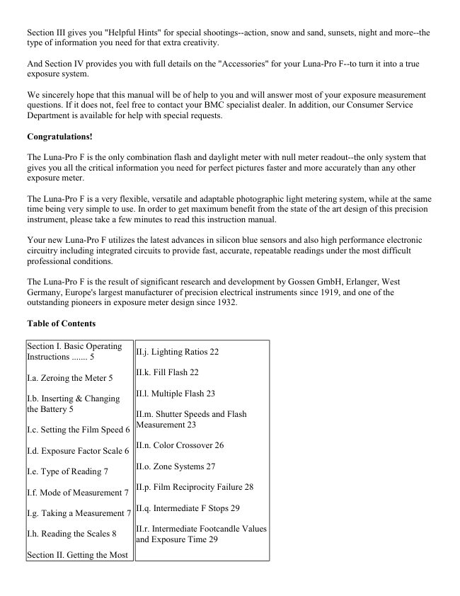
Table of Contents

Section I. Basic Operating
                                          II.j. Lighting Ratios 22Instructions ....... 5

                                    II.k. Fill Flash 22
I.a. Zeroing the Meter 5

                                          II.l. Multiple Flash 23
I.b. Inserting & Changing
the Battery 5
                               II.m. Shutter Speeds and Flash
                         Measurement 23
I.c. Setting the Film Speed 6

                                    II.n. Color Crossover 26
I.d. Exposure Factor Scale 6

                                    II.o. Zone Systems 27
I.e. Type of Reading 7

                                    II.p. Film Reciprocity Failure 28
I.f. Mode of Measurement 7

                                    II.q. Intermediate F Stops 29
I.g. Taking a Measurement 7

                                        II.r. Intermediate Footcandle Values
I.h. Reading the Scales 8
                         and Exposure Time 29

Section II. Getting the Most
View original page 2Page 3 · Read text
Out of Your Luna Pro 11     Section III. Helpful Hints a.... 30

II.a. Continuous or Stored     III.a. Choosing Between Action
Readings 11                Stopping Ability and Depth-of-Field
                        30
II.b. The Null Method of
Measurement 12                III.b. Snow & Sand ............ 31

II.c. Exposure Correction      III.c. Sunsets 31
Dial 13
                                    III.d. Night Lighting 32
II.d. Footcandle Readings 14
                                     III.e. Backlighting 32
II.e. Carrying Case 15
                                         IlI.f. Copying 33
II.f. Methods of
Measurement 15                III.g. Excessive Skylight 33

II.g. Incident Measurement    III.h. Bellows (Extension) Factor 34
17
                            Section IV. Accessories 37
II.h. Reflected Measurement  Section V. Appendix 40
18                          Service 41
                              Specifications 42
II.i. Scene Brightness Range  Additional Reference Material 43
20
View original page 3Page 4 · Read text
Operating Parts & Scales


1. Spherical Diffuser

2. Green Zero Check Point

3. Meter Needle

4. Power Switch

5. Electronic Flash
Reference Mark

6. Cine Scale

7. Mode Selector

8. ASA Index Triangle

9. Film Speed Scale

10. Exposure Correction
Dial

11. Computer Dial


12. Battery Test Zone

13. Flash Range Indicator

14. Exposure Time Scale

15. Aperture Scale

16. Battery Test Button

17. Exposure Correction Signal

18. Film Speed Setting Disk

19. Exposure Value Scale

20. Zone System Scale

21. Exposure Factor Scale Index Mark
View original page 4
Page 5 · Read text
22. Measuring Cell Window (under
                                     24 Table of Foot candle and Lux Values
diffuser)

                                            25. Battery Compartment Lid
23. Zero Adjusting Screw


Basic Operating Instructions

The following instructions are a quick operating guide to the Luna-Pro F. For best results, also read the
additional sections describing in detail the different functions and applications of the Luna-Pro F.

1. a. Zeroing the Meter


                                            With the battery removed, check to see that
                                                       the meter needle (3) rests on the green zero
                                                check point (2). If not, turn the zero
                                                       adjusting screw (23) until the needle rests on
                                                       the zero mark.


1. b. Inserting & Changing the Battery


Your Luna-Pro F is supplied with a 9-volt battery which fits into the battery compartment at the bottom of the
meter. Slide the battery compartment lid (25) off and attach the battery to the battery clip inside. Note that the
battery can only be connected one way. Insert the battery into the battery compartment and slide the lid back on.
Check the battery by pushing and releasing the power switch (4) and then pushing in and holding the battery
test button (16). The meter needle should be well within the battery test zone (12).
View original page 5Page 6 · Read text
1. c. Setting the Film Speed


GOSSEN Luna-Pro F


                                              Determine the ASA speed from the data
                                                   supplied by the film manufacturer. Rotate the
                                                        clear film speed setting disc (18) by the raised
                                                    bars until the ASA speed number is opposite
                                                     the white ASA index triangle (8). A detailed
                                 ASA film speed table is on page 40.


1. d. Exposure Factor Scale


                                          Check to make sure that the exposure factor
                                                      scale index mark (21) is at 1. A more detailed
                                                   explanation of this useful scale is on page 10..
View original page 6Page 7 · Read text
1. e. Type of Reading


Select the method of measurement desired,
either reflected or incident. (For details on
incident vs. reflected measurements, see
section 11. f.). For reflected readings slide the
spherical diffuser (1) to


1. f. Mode of Measurement

Select the mode of measurement desired, either flash or daylight (ambient light). For daylight measurement, the
red mode selector (7) should be in the depressed position; for flash measurement the mode selector should be in
the raised position. Depress and release the mode selector to change the mode of measurement (i.e., from flash
to ambient). There is a graphic illustration on the side of the meter which shows the positioning of the mode
selector necessary to take f lash or ambient readings.

Note: The flash mode can be used for taking incident or reflected readings.

1. 9. Taking a Measurement

Follow Basic Operating Instructions steps 1. a. thru I. f.

For daylight measurement, mode selector (7) should be in the depressed position (see Section I. f.). Aim the
meter at the subject for a reflected light reading or at the camera for an incident reading. Depress and release the
power switch (4). Rotate the computer dial (11) until the meter needle is over the "0" null line. Read the desired
combination of f/stop and shutter speed on the computer scales.

For flash measurement, mode selector (7) should be in the raised position (see Section I. f.). Aim the meter as
indicated above. Depress and release the power switch (4). Fire the flash. Rotate the computer dial until the
meter nulls. It is important to note that the red zero mark on the exposure correction dial should remain between
the two red triangles on the meter face when pulling. If the zero mark goes beyond either of the red triangles,
the flash intensity is beyond the range of the meter. When past the right triangle the light level is too low. When
past the left triangle, the light level is too high.

Read the proper f/stop opposite the red flash indicator on the computer dial. This indicator is located between
the 1 and 2 second exposure marks.
View original page 7
Page 8 · Read text
NOTE: When you release the power switch, the value measured at that moment will be automatically read, and
electronically stored by the Luna-Pro F. To conserve battery life, the meter switches itself off automatically
after 30 seconds. and your measurement set on the computer dial remains for convenient and repeated reference.
For continuous measurements, see Section II. a.

1. h. Reading the Scales

The Luna-Pro F has seven scales to give you information on ASA, aperture shutter speed, cine speed, exposure
value (EV), exposure factor (EF) and Zone System values.

The time, or shutter speed, scale is calibrated from 1/4000 of a second to 8 hours and indicates values as
follows:

Hours are indicated 8h, 4h, etc.
Minutes are indicated 30m, 15m, etc.
Seconds are indicated 30,15, etc.
Fractional seconds are indicated,'2, '4, etc.

Note that each section is alternately colored from the adjacent sections for ease of reading. The red 11 indicates
the proper reading point when using the flash measurement mode.

The ASA scale is calibrated in standard ASA values from 0.8 to 100,000 (100K). Intermediate values are shown
by short lines. A complete table listing these intermediate values in on page 40.

CAUTION: Because of the extreme measuring range of the Luna-Pro F it is possible--under exceptional
conditions of very high light levels combined with a very high ASA index--that the computer displays both ends
of the exposure time scale (8h and 1/4000 sec.). When this occurs, the CORRECT reading will be the UPPER
part of the scales!

EXAMPLES:

ASA 25,000 at HIGHEST LIGHT LEVEL:

Scales show above 1/4000 sec. at f/128
but also (below) 8 hours at f/5.6 etc.

Obviously, HIGH ASA and HIGH light level add up to SHORT exposure--1/4000 sec. at f/128.

The aperture or f/stop scale is calibrated from f/128 to f/0.7. Numerical values are shown on the scale at full
f/stop increments. Intermediate values are indicated by short lines at 1/3 stop increments. A table of
intermediate values and the mathematical formula for calculating f/stops are given in Section III.
View original page 8
Page 9 · Read text
The cine scale allows direct reading of
                                                     apertures for various cine speeds (frames per
                                                    second). These speeds correspond to actual
                                                exposure times on the exposure time scale
                                                only for cameras having standard shutter
                                                      angles. For XL cameras or those with
                                                     adjustable shutter angles, consult the camera's
                                                        instruction book for the equivalent shutter
                                                 speeds and read your exposure opposite that
                                                speed on the time scale. Also note that some
                                                        reflex viewing movie cameras use beam
                                                              splitters to provide a light path to the viewing
                                                      screen. These beam splitters reduce the light
                                                        intensity to the film plane, so that a correction
                                                        factor must be applied to the indicated f/stop.
                                         Once determined, the correction can be
                                          programmed into the exposure correction dial.


An EV (exposure value) scale (19) is provided for cameras with shutters calibrated in EV. The LunaPro F EV
scale is calibrated from -8 to + 24. Numerical values are shown for full EV values with intermediate values
indicated by short lines at 1/3 EV intervals Exposure values are used elsewhere | on several scales which will be
explained later. It is I important to remember that a change of 1 EV is I equivalent to a change of 1 f/stop.

An EF (exposure factor) scale is included for making exposure corrections when using filters, bellows,
extension tubes, etc. It is calibrated for exposure factors up to 64. Detailed information on this scale is in
Section II. c. The zone system scale provides you with the capacity to read lighting ranges (in zone system
values I thru IX) directly from the computer dial of the meter. Further information on zone systems can be
found in Section II. k.

SECTION II

Getting the Most Out of Your Luna-Pro F

The preceding condensed instructions gave you information on the basic operating procedures for your Luna-
Pro F. However, this meter is extremely versatile, and the following information will acquaint you with the
many creative possibilities available to you when using your Luna-Pro F.

11. a. Continuous or Stored Readings

The Luna-Pro F is capable of either continuously reading or storing light values. For simplicity of operation, the
read and hold method is used. The continuous method of measurement can be used for the evaluation of
different lighting levels (such as when using zone systems) as well as the measurement of commutative flash.

To operate the meter in the read and hold mode, the power switch ON/OFF button index mark (A) must be
aligned with the square switch position indicator (B). Simply depress and release the power switch. The meter
will automatically read and electronically hold the value of the light level present at the moment when the
button was released. Because advanced electronic circuitry and a silicon blue cell are used in the Luna-Pro F.
the measurement is instantaneous with no memory or lag. The reading will be stored and available for a period
View original page 9Page 10 · Read text
of thirty seconds after the button is released. After this period, the meter automatically turns itself off,
prolonging battery life. Additional readings can be taken at any time by repeating the above sequence.


                                       To operate the meter in the continuous mode,
                                               simply depress and hold the ON/OFF button
                                                               in. The meter will now respond to all changes
                                                        in light values. For long term measurements,
                                                     the ON/OFF switch has a lock position which
                                                                 is indicated by the round switch position
                                                       indicator (C). To activate and lock the meter
                                                   on:


1) Depress and hold the power switch in.
2) Rotate the switch button clockwise until the index mark is aligned opposite the round switch position
indicator.

The meter will now remain on for constant readings until the switch button is rotated counterclockwise opposite
the square position indicator where the read and hold mode will go into operation for one minute, after which
the meter will again turn itself off.

NOTE: Be sure to return the switch button to the read and hold position (square mark) after using. Failure to do
so will result in short battery life.


II. b. The Null Method of Measurement

Laboratory instruments have long used the null method of measurement for obtaining precise readings. This
method has been incorporated into your Luna-Pro F for maximum accuracy and ease of reading.

The basic operating difference between the LunaPro F and a conventional meter is that, instead of using various
points along a complete scale length only one position (the null point) is used for all readings and at all light
levels. This results in greater accuracy and ease of operation. There is no need to change scale ranges or to read
different scales. When the needle is set at the null point, the computer instantly shows a complete read-out of
the measurement.

To expand the capabilities of the Luna-Pro F further, its meter face is also calibrated in 1/3 EV increments from
the null position to + 3 EV for use in scene brightness measurements, zone system applications and lighting
ratio measurements. Additional information on this extremely useful feature will be found in Section II. i.

If the meter needle is placed in "over" or "under" range, the readings on the calculator dial will result in over or
underexposure by the value indicated compared to a standard exposure.

Each numerically indicated major division on the meter face equals one EV (a change of one EV equals a
change by one f/stop or one shutter speed setting); the small intermediate dots are equal to 1/3 EV.
View original page 10Page 11 · Read text
11. c. Exposure Correction Dial

Occasionally, the indicated exposure readings obtained with any light meter must be modified for best results.
This is especially true when using filters or when taking close-up pictures where the longer lens to film distance
results in reduced light at the film plane. To correct for these effects, commonly called filter factor and bellows
(extension) factor, additional exposure must be given to the film. In addition, you may, for various creative
reasons, wish to depart from the standard exposure values. For these situations, the Luna-Pro F with its
exposure correction dial, is ideal.

Normally when making exposure corrections, the correction factor must be calculated and applied each time a
reading is taken. However, with the Luna-Pro F the exposure change can be programmed into the exposure
correction dial. Any readings will then be automatically corrected.

The exposure correction dial is calibrated to work both in EV (exposure value) and EF (exposure factor). Two
index marks are provided at the center or normal positions for each correction method. In addition, the red
exposure correction signal (17) gives a visual indication any time the exposure correction dial is in use.


                                       To use the exposure correction feature,
                                                 determine the correction factor desired, in
                                                         either EV or EF, and rotate the exposure
                                                     correction dial while holding the computer
                                                      ring stationary until the white index mark is
                                                   opposite the correction value desired. Any
                                                   readings now taken will reflect this correction.


For example, assume that a filter with a filter factor of 4x is being used. This represents a change of 2 stops. By
moving the index mark of the EF ring to a position opposite the number 4, the meter readings will automatically
be compensated for the 2 stop difference.

Rotating the exposure correction dial corrects the indicated exposure by changing the shutter speed (and flash
symbol), cine speed, and EV scales. Therefore, this feature can be used for still photography using available
light and artificial light including flash, motion picture photography, and with cameras calibrated only in EV.

After completing "corrected" measurements, be sure to return the correction dial to its "O" position (red signal
will be covered by black tab).

11. d. Footcandle Readings With The Luna-Pro F

The Luna-Pro F is a precision instrument designed to give highly accurate photometric readings specified in
readily usable photographic terms. However, footcandle readings can also be obtained with the Luna-Pro F
either by converting the photographic reading or by use of an accessory snap-on foot candle scale.

A conversion table of EV to foot candle readings is included on the underside of the meter. To determine the
equivalent foot candle reading, set the ASA film speed scale to 50, slide the spherical diffuser over the cell
window for incident readings, point the meter toward the light source, and take an EV reading (null the meter).
View original page 11Page 12 · Read text
Turn the meter over and read the foot candle value opposite the EV reading just obtained. Similarly, lux values
can also be determined. Note that for each change of one EV, the foot candle level changes by a factor of 2.
This is because the EV scale is equivalent to a full stop scale in that each change of one EV or one f/stop results
in either twice or half the amount of light. A formula suitable for calculating intermediate values of foot candles
is given in Section III along with pre-calculated values at 1/3 EV.


                                            The most precise foot candle readings are
                                                     obtained by means of a flat diffuser. When
                                                    using the spherical diffuser of the Luna-Pro
                                                         F. all the light falling on the diffuser from
                                                an angle of approximately 180° is
                                                         integrated for a final reading.


 Since most photographic subjects are three dimensional, this results in more accurate photographic exposures,
but can give improper foot candle readings.

When using the spherical diffuser, footcandle readings are most accurate when reading direct light beams such
as from spots, arc lights, etc.

11. e. Carrying Case


                                       Your Luna-Pro F is supplied with an exceptionally
                                                strong and functional carrying case. It is
                                                constructed of the finest heavy-duty materials for
                                             long life and extra protection for the meter. Extra
                                                  thick material and heavy stitching make this case
                                                   suitable for the abuse encountered in professional
                                               usage. The complete top section of the case is
                                           removable for ease of handling when taking
                                                frequent exposure readings.


To insert the meter, open the case by unsnapping the fastener at the rear of the case and swing the top section
forward. Insert the meter strap through the openings at the rear of the case. Place the meter into the bottom
section of the case and secure with the retaining strap. To remove the top section of the case completely, unsnap
the fastener at the bottom of the case.

11. f. Methods of Measurement

There are two basic methods of obtaining measurements with the Luna-Pro F. incident and reflected light
readings. Both methods are popular and when used properly, both are valid and will give good results.
However, to evaluate properly the ways in which these two methods function, it is necessary to discuss briefly
how the meter operates and how film responds to light. It is beyond the scope of this manual to get into a
detailed discussion of sensitometry, the study of tone reproduction. There are many excellent books available on
the subject some of which are listed in the appendix. This manual will just relate in simple terms, how the Luna-
Pro F works and under which conditions you may wish to use either incident or reflected light readings.
View original page 12Page 13 · Read text
All films have characteristic responses to light which, although they may vary from film to film and with
changes in storage and processing, are relatively predictable. This consistency of response is what allows the
use of light meters and other photographic instruments to predict the final outcome of an exposure.

Film responds to only a limited range of illumination levels before its ability to record that light illumination
level properly is lost. Any instrument designed to measure or expose film must take that into consideration. The
response of the film to light is generally graphically illustrated by what is called a "characteristic curve" or H &
D curve, named for Hurter and Driffield who originated its use.

Although it is not necessary to use such a curve to determine exposures, using one as an illustration will help in
evaluating proper light measuring techniques. A representative sample H & D curve for a film is illustrated
below.


RELATIVE LOG E

This curve shows, among other things, the change of density of the film vs. the "log" of the exposure. With
negative film, as the exposure increases, the negative density increases. It is broken down into three distinct
regions, the toe, straight line portion, and shoulder. In order to record detail properly on film, the light values
(log exposure) should fall within the range where they intersect the straight line portion of the curve. If the
exposure falls into the area of the toe or shoulder, the film will lose shadow or highlight detail respectively. This
is because, once those areas are reached, little or no change in film density occurs with a change in exposure,
and it is the change of density that produces differentiation and detail. Therefore, your light meter must give you
an exposure value that will adjust the measured light so that when it reaches the film, it will fall within the
straight line portion of the film's recording ability.

The H & D curve shown above indicates relative log exposure. However, because different films have different
light sensitivity ranges, which would affect the density vs. log exposure in actual use, the meter must be
programmed for these differences. The ASA film speed setting control on the calculator dial of the meter
accomplishes this programming.

In order for this ASA value to be meaningful, all meters and other light measuring devices that relate to
photographic applications must take into account not only the film speed, but also the reflectivity of the object
being photographed. This is because the film does not know what the reflectivity of a particular object is. It only
responds to light levels. Therefore, all other conditions being equal, a light subject with a low level of
illumination may record on film the same as a dark object with a high level of illumination. To standardize these
varying conditions and to allow you to work with different meters and films, a reflectance of 18% value and the
understanding that it represents a "typical average" is the basis for readings taken with both reflected and
incident methods of measurement. However, under the same lighting conditions, different readings for the same
scene can be obtained when using both methods, depending on subject reflectivity.
View original page 13
Page 14 · Read text
This may seem strange at first, but it is true, and sometimes causes confusion. To eliminate this confusion
(something no meter or other device can do), you must consider your subject matter and how you want it to
appear on the film. For simplicity, the discussion of this evaluation method will be broken down into a
discussion of incident and reflected light measurements.

11. 9. Incident Measurement

When reading incident light, the spherical diffuser is placed in front of the measuring cell window and pointed
toward the camera, i.e. opposite the subject being photographed, so that the diffuser will receive the same light
intensity and distribution as that falling on the subject. The reading at this point indicates the strength of the
light, but does not indicate the light value reflected from the subject into the camera lens and onto the film. It
does not indicate the light value that would be reflected into the lens from an 18% average reflective subject.


                                     Therefore, when working with subjects that are primarily
                                   very light or very dark, the incident exposure reading
                                      indicated should be adjusted to compensate for the difference
                                        in reflectivity from the 18% standard. When the subject is
                                   very light decrease the exposure by 1/2 to 1 f/stop. When the
                                      subject is very dark, increase the exposure by 1/2 to 1 stop.
                              The amount of change to the exposure will depend on your
                                 judgment as to the degree of variation in subject reflectivity
                                from an average scene (18% reflectivity).


Situations may arise where you have extremes of light and dark subjects, all of which are important in the same
scene. Under these conditions, the meter should be used in the reflected light method as described under scene
brightness range and zone systems.
Incident light readings are most valuable when determining exposures where the subject is inaccessible and
receives the same illumination as the meter. They also allow you to determine the individual strengths of
multiple light sources striking one subject by reading each source independently. In most cases with average
subject matter, the incident method is a fast, simple and accurate way to determine exposure.

11. h. Reflected Measurement

When reading reflected light the meter is pointed toward the subject from the camera position without the
spherical diffuser (1) over the measuring cell. Light reflected from the subject passes through a collecting lens
onto the measuring cell. This is the same type of path the light takes when exposing film in your camera. The
meter cannot "read" any single element in its field, such as a face or highlight; it integrates all the light reflected
throughout the measuring field, and indicates an exposure which will record the total picture on the basis of an
overall 18% value.

In most cases, you can simply use this reading to get a perfectly exposed picture. However, there are a few
situations where the readings should be modified.
View original page 14Page 15 · Read text
The Luna-Pro F has a measuring angle of 30° when taking a
                                          reflected reading. The light from all objects within that 30°
                                   measuring range will be averaged to give you the final
                                        reading. If you have one or more objects that are
                                          significantly lighter or darker than the rest of the scene, the
                                        objects will bias the reading away from the average. In
                                      cases such as this, the meter should be moved in closer to
                                        the main subjects of interest or one of the accessory spot
                                     attachments used to eliminate the effect of the light or dark
                                          areas. As an alternative, an incident reading can be taken.


When measuring a subject that departs significantly from an 18% reflective surface, you may wish to modify
your readings. This is because the reading indicated will make the subject appear on the film as if it were 18%
reflective.

In certain cases, you may not want the subject being measured to fall into that category. For example, if a
reflected reading is set in your camera when measuring a brilliant white bridal gown, the resulting image of the
gown on the film will appear with the same density as if it were 18% gray instead of white. Here again, you
may wish to use an incident reading or compensate the reflected reading by increasing exposure. The same is
true for very dark objects, i.e., a black tuxedo, except the exposure would be decreased.

Reflected readings are particularly useful when trying to evaluate the relative range of reflected light from
various subjects that may have different reflectivity and may be receiving different amounts of light. Because
the reflected reading measures the light reaching the lens, differences in subject reflectivity and level of
illumination are accounted for. Therefore, you can determine the extremes and distribution of light from the
scene just the way your film will record it. This technique is covered in sections Scene Brightness Range and
Zone Systems.

II. i. Scene Brightness Range


                                                In order to assure proper exposures for highlight
                                         and shadow detail in scenes with a wide range of
                                                      light intensity and subject reflectivity, the extent of
                                                 the lighting range must be determined. The
                                        LunaPro F is ideally suited to this type of
                                         measurement because of its null meter design.


To utilize this function, you must first determine by testing the limits of exposure change for highlight and
shadow areas from average that are acceptable to you with your film. Once this is done, the calibrated reference
scales on the meter will automatically indicate if you are within acceptable limits of the film.
View original page 15Page 16 · Read text
For example, if your testing with a particular type of film shows that you could accept an exposure change from
average of UNDER (under exposure) 2 to OVER (over exposure) 2 1/2 EV, your total range would be 4 1/2 EV.
Using reflected measurement, you could then read the light from the most important area of the scene and then
null for that reading.


Then, without further adjustment of the calculator dial, you could take light readings from highlight and shadow
areas and read the EV variance of these areas. If, in this case, the readings fall within the UNDER 2 to OVER 2
1/2 EV range, your exposures will be good. However, if for example, your readings resulted in UNDER 3 and
OVER 1, you would lose shadow detail, even though the total range is still only 4 EV. A simple solution would
then be to reread the shadow intensity and rotate the computer dial until the meter needle is opposite 2 on the
UNDER side which is within the film limits.


                                         Then recheck the highlights which should now
                                                 read OVER 2. You would then use the new
                                              exposure setting indicated on the computer dial.
                                        The scene brightness range has not changed, but
                                                   the meter has adjusted to your exposure so that
                                          you are working within the range of the film. To
                                                 see this graphically in terms of film response see
                                                   the H & D curves to the right.

                                                                      It is important to note that this exposure
                                               adjustment method works best when using
                                                 negative films because different density levels
                                             can be adjusted for in printing. With
                                                 transparency films, this type of exposure
                                               adjustment should be used very carefully
                                              because you are viewing the original without the
                                                     benefit of printing correction.


With transparencies, about 1 EV is the largest practical shift if your main subject is close to 18% reflectance.


                              Situations may arise where the meter shows a range of light intensity
                                that is beyond the total range of film acceptance. In these cases, the
                           use of fill light to lighten shadows or a "gobo" (a device to block or
                         modify light such as a dark card) to soften highlights may be
                               indicated. When the proper corrective action is taken, the scene
                             brightness range can again be checked to be sure the limits of the film
                              are not exceeded. Modifying the lighting can also be used instead of
                               shifting the exposure as mentioned above if so desired, as in the case
                             of transparency film where the main subject is close to 18%
                              reflectance such as with some skin tones.
View original page 16Page 17 · Read text
11. j. Lighting Ratios

Lighting ratios, the relative strengths of different lights in a scene, can be used to create certain moods or
effects. Sometimes, manipulation of lighting ratios is needed to hold detail in shadow and highlight areas.

To determine a lighting ratio, take an incident reading of the main light and null the meter. Then, without
readjusting the computer dial, read the other light or lights in the scene. When reading the secondary lights,
deflection of the meter needle will indicate the strengths of those lights in relation to the main light. The method
of reading lighting ratios is similar to that described under Scene Brightness Range.

11. k. Fill Flash

When lighting ratios are very high, the difference of the light levels in the areas of direct light and shadow may
be so great that the film will not be able to record detail in both areas at the same time. If this occurs, a useful
technique for bringing lighting ratios to a more manageable level is fill flash.

By using supplemental flash, generally electronic flash, a sufficient level of light can be introduced into the
shadow areas to make proper recording of detail possible. The Luna-Pro F is a useful tool in determining the
relative strengths of available light and flash illuminating the scene and can help to adjust to the proper lighting
ratios.

Example Method I:

Assume you are shooting a scene where, in order to hold detail in a shadow area, you want the shadow exposure
to be 2 stops under the mid-tone reading.

1) Take an incident reading and null the meter.
2). Without moving the computer dial, read. in the shadow area. The needle deflection indicates the shadow is 3
stops under your mid-tone (incident) reading. If you wish, electronic flash can be used to bring more light into
the shadow area and bring the shadow illumination into the desired range.
3) Select your working aperture and shutter speed from the initial incident reading (i.e., at 1/125th second).
4) Since you wand the shadow area to be 2 stops under the mid-tone, set the flash mark (5) at f5.6 (2 stops
under f11).
5) Take a reading (with the Luna-Pro F in the flash mode) with the flash unit directed toward the shadow area.
6) Manipulate the flash unit (changing the position or power control) until the meter needle deflects to the null
point. Make sure that little, if any, ambient light strikes the measuring cell of the meter.

If you have a leaf shutter camera and are not able to adjust the flash, you card determine fill flash exposure by
adjusting the. aperture and shutter speed settings.


Example Method II:

Follow steps 1 to 3 as indicated for Method I.

4) Fire the flash into the shadow area and take a reading with the Luna-Pro F in the flash mode. Let us assume
that the flash is not powerful enough to bring the exposure into the two stop range and the Luna-Pro F indicates
an exposure at f4.

5) Change your initial exposure to 1/250th second at f8. Note that this will give you the same exposure value as
1/125th second at f11.
View original page 17
Page 18 · Read text
6) The flash reading of f4 is now within the desired two stop range of the mid-tone reading at f8.

When doing any work with flash, you must work within the camera's 'sync' speed (the shutter speed at which
the flash will synchronize with the shutter).

II. I. Multiple Flash

Occasionally the light output from a singular flash may not be sufficient to enable you to work at the f/stop
desired. When this happens, multiple flashes may resolve the problem. The Luna-Pro F can assist you in
measuring the cumulative exposure of multiple flash.

Example:

The indicated f/stop, after your initial flash measurement is full; you wish to work at f22. Adjust the computer
dial until the red flash reference (5) lines up with f22. With your Luna-Pro F in the flash mode, reset the meter
and leave the power switch in the continuous read position. Repeatedly fire the flash. Count the number of flash
needed to null the meter (bring the meter needle to the zero point).

It is important to note that for each f/stop increase desired you must double the number of flashes. Therefore, if
your desired f/stop is more than a few stops away from the indicated f/stop, this method becomes impractical.

II. m. Shutter Speeds and Flash Measurement
Most electronic flash units have a relatively short duration. Therefore, actual film exposure by the flash is not
affected by changes in camera shutter speed as long as synchronization is maintained. However, changes in
shutter speeds will alter the effect of ambient light on the overall exposure. (As the shutter speed changes, the
portion of the total exposure caused by the flash remains constant, but the portion caused by the ambient light
will vary.) As long as the flash output is considerably higher than the ambient, this effect can be ignored. But
when the level of ambient light exposure approaches that of the flash, attention must be given to the effect of
shutter speeds. The circuitry of your Luna-Pro F is designed to indicate the f/stop which will produce correct
overall exposure with a shutter speed of 1/100th to 1/125th second. If the ambient light is extremely bright, and
a different shutter speed is used, the indicated f/stop may have to be modified to compensate for variations in
ambient exposure caused by the change in shutter speed. To determine if compensation is required, two parallel
measurements must be taken from the same position:

1. Normal measurement (flash and ambient light) with the Luna-Pro F in the flash mode.
2. Measurement of the ambient light with the LunaPro F in the ambient/daylight mode.
3. Compare the different F-Stops indicated for a shutter speed of 1/125th second in flash and ambient modes.

Any difference between the two readings calls for an f/stop modification as shown in the table below.

1. Combined measurement (flash and ambient light) with the Luna-Pro F in the flash mode.
2. Measurement of the ambient light with the Luna-Pro F in the ambient/daylight mode.
3. Compare the different F-stops indicated for a shutter speed of 1/125th second in flash and ambient modes.
Any difference between the two readings calls for an f/stop modification as shown in the following table:
View original page 18
Page 19 · Read text
Example:
Luna-Pro F indicates f8 for a flash reading and f5.6 at 1/125th second for an ambient/daylight reading. The
difference (f8 and f5.6) is one stop. If the shutter speed to be used is increased to 1/500th second the table below
indicates that the lens must be opened up by 2/3 stop from the reading indicated by the Luna-Pro F. The higher
the shutter speed (1/500th second vs. 1/125th second) will decrease the ambient light contribution to the
exposure. Opening up the lens 2/3 f/stop will increase the ambient light contribution, bringing the ambient/flash
ratio back to the original.


II. n. Color Crossover
The proceeding discussion concentrated on the effects that lighting can have on film, either black and white or
color. However, with color, three separate emulsions are on the film each of whose individual response may be
different. In normal exposure situations all three layers will track reasonably well, resulting in accurate
rendition of color as well as density. However, at the extremes of exposure levels, deviations in the
characteristic response of individual color layers of the film can result in a condition called color crossover.
This condition results in a color shift in an area of under or over exposure that cannot be corrected without
affecting the colors of the properly exposed areas of the scene. It is therefore very important to avoid this
condition which shows itself as color shifts in the shadows and highlights.

II. o. Zone Systems
There are times when the lighting range cannot be brought within the acceptable limits of the film because of an
inability to fill or use "gobos" (as spelled in manual) such as when photographing landscapes. When these
situations arise, the exposure levels can be adjusted so that the most important parts of the scene receive proper
exposure. This can be done with either black and white or color film. However, some detail, either in the
highlight or shadow areas, will be lost.

When using black and white film, another technique is available to extend the capabilities of the film to record
extreme lighting ranges. It is called the zone system. Instead of relying on standard measurement and exposure
techniques, the zone system combines special measurement techniques, modified exposures, and altered film
processing to expand the range of light values that the film can accept. In doing so, detail can be recorded which
would otherwise be lost.

A complete discussion of this technique is far beyond this manual. References are given in the appendix which
should help you become familiar with this very useful photographic tool.

The Luna-Pro F is well suited for use with most zone systems because of its null meter principle of operation
and the zone system scales (20). Most systems are based on a central zone, representing a certain lighting level
called Zone 5. From this level, the range of light from highlight to shadow is measured and referred to this
central zone. The level of variance from the central zone determines the amount of exposure correction and
processing modification, if any, that is needed. With most meters, the zone equivalents must be marked on the
face or transferred to another sheet to correlate with changes in light level. However, with the LunaPro F. the
computer dial can be used to adjust the meter needle at any light level. Any subject can be nulled for and light
variations from that level read in zone system values I thru IX directly off the meter face in EV. This means that
you can always set null for Zone 5. Or, you may wish to bias the reading in one direction.
View original page 19
Page 20 · Read text
Simply turning the computer dial of the Luna-Pro F allows you to put the meter needle anywhere from -3 to + 3
EV from a normal value.

To use the zone system scales of the Luna-Pro F. take a measurement of a central zone (Zone V), noting the
corresponding EV values for each zone value. Using the EV scale as a reference point, measurements of
highlight and shadow areas can then be translated into zone values.

Example:
Take a reading of a central zone or mid-tone (Zone V) and null the meter. Assume the EV indicated for Zone V
is '8'. Note the EV values indicated for the other zone values. In this example:

Zone I = EV 4 Zone VI = EV 9

Zone II = EV 5 Zone VII = EV 10

Zone III = EV 6 Zone VIII = EV 11

Zone IV = EV 7 Zone IX = EV 12

Zone V = EV 8

Now you can take a reading of a highlight area, null the meter and note the EV indicated. Assuming the
highlight reading corresponds to an EV 12, the zone value would then be Zone IX (see chart above). Now take a
shadow reading, null the meter and note the EV indicated. Assuming the EV value is '5', the corresponding zone
value would be a Zone II.

The zone system scale of the Luna-Pro F enables you to easily measure zone system values and establish
information regarding tonal range in a scene.

In the example above, Zone V (a mid-tone) is used as a reference point; however, with the Luna-Pro F you can
select any zone or light level as a reference. A reading is taken of a particular area, the meter is nulled and the
EV value noted (i.e., EV = 7). If you would like that area to be represented as a Zone III rotate the computer
dial until EV 7 is directly above Zone value lilt At this point, a reading of the appropriate apertures and shutter
speeds will render the particular area measured as a Zone III.

With a little practice, you will be amazed at the ease of obtaining this specialized information.

11. p. Film Reciprocity Failure
All photographic exposure meters rely on a principle of film exposure called reciprocity, to function properly.
Basically, the film integrates or adds up light during exposures to produce the latent image. Within certain
limits, the same image density is achieved for short exposures of high intensity as with long exposures of low
intensity, as long as the product of intensity times time is constant. When the exposure times get very long or
very short, however, this reciprocity effect is lost, and an accurate prediction of exposure, and color balance
with color films, cannot be determined solely by the meter reading. It is therefore important to check the
instructions supplied with the film in use to determine when reciprocity failure can be expected, how severe it
will be, and how to correct for it. Here again the Luna-Pro F greatly assists in exposure determination because
the corrective filters suggested by film manufacturers to adjust color shifts from reciprocity failure have an
effect on exposure. These filter factors can be programmed into the Luna-Pro F and the new, corrected f/stop
read directly.
View original page 20
Page 21 · Read text
11. q. Intermediate f/stops
The Luna-Pro F is calibrated in 1/3 f/stop increments with numerical indications at full stops. A table is
included below with the actual numerical values of the 1/3 stop increments listed for levels from f/0.7 to f/128.
Values not listed can be calculated from the formula that follows.


For example, if you wish to stop down 1/4 stop from f/4, take the square root of 2: which equals 1.414 and raise
it to the power.25 which is the decimal equivalent of 1/4 stop.


11. r. Intermediate Foot candle Values and Exposure Times
Calculation of intermediate values of foot candles and exposure times is basically the same as calculation of
intermediate values of f/stops except that the value square root of 2 is replaced by 2 in the formula.

For example, you have a foot candle level 1/2 stop above 700 as represented on the chart on the back of the
Luna-Pro F.

New foot candle level = (old level) (2(f/stop change))
= (700) (2( ))
= (700) (1 .41 4) = 990

SECTION III

Helpful Hints

111. a. Choosing Between Action Stopping Ability and Depth-of Field
After taking a light reading with your Luna-Pro F you will have a choice of readings to use which may look like
this:

Time:            1/1000            1/500             1/250             1/125
f/               2                   2.8              4                   5.6

Time:             1/60              1/30               1/15               1/8
f/               8                11               16               22


All of them will give good exposures, but, in terms of photographic results, they are all slightly different.

When shooting action, you generally need a faster shutter speed to get a sharp photograph. Speeds from 1/125
to 1/1000 are generally used, with the choice depending upon the relative speed and direction of travel of the
object. Objects moving toward or away from you can be stopped with a lower shutter speed than those moving
across your field.
View original page 21
From the M. Butkus archive. Original publisher and archive notices are retained.
Check the model and edition against your equipment.
PDF verified 2026-10-10.