Light meters
Gossen Sinar six User manual
User manual for Gossen Sinar six. 39 pages in English. Read the original PDF, download or print a copy without registration.
39 pagesEnglish3.0 MB PDF
Loading your manual…Open PDF directly
Document details
- Brand
- Gossen
- Model / document
- Gossen Sinar six
- Document type
- User manual
- Language
- English
- Pages
- 39
- File size
- 3.0 MB
- Category
- Light meters
- Document date
- Not specified in catalog
Search available document text
Find a term, then jump to its page in the original PDF. Image-only pages may not be searchable; check the PDF for exact wording and diagrams.
Page 4 · Read text
www.butkus.us
   Read these Instructions   !
      The SINARSIX has been designed-through years of development and testing-
         particularly for the expert user of the large-format camera in order:
       to reduce more effectively than was previously possible, the large wastage due to
        incorrect exposure;
    o to eliminate tiresome calculations;
    O to do away with the complications in the determination of exposure times affected
      by reciprocity  failure, and when using of photographic materials of different sensi-
          tivity, etc.;
       to measure light on the film plane without the adverse effects of the ground-glass
       screen or fresnel lens, or errors caused by wide angle lenses and camera movements.
      to enhance the exposure quality of your pictures and to control it more reliably
       than hitherto.
        In other words: to render exposure measurement as accurate and yet as simple as
     possible.                                                                      r
     What is of particular significance to the professional  is the fact that the measuring
       area of the SINARSIX amcunts to no morethan about 1f .soof the 4xb in. or 9x12 cm
       format. For the photographer using large-formats this provides the facilities of
        selective image field measurement, which is impossible with small formats.
         In order to secure these important advantages, you have purchased your SINARSIX.
     Now you must use it properly.This involves unlearning part of your previous measur-
        ing habits. These new Instructions will re-train you step by step and in the simplest
       possible manner.
       Give yourself time; peruse each chapter-with the SINARSIX at your elbow-until
      you have mastered its operation.                                                     -       Your patience will be rewarded.


 '{]
'.*


w
          Text and lllustrations                                            Printed in Switzerland
         Copyright Carl Koch, Schaffhausen/Switzerland                Reprints - also of extracts - prohibited
                                                                               3
View original page 4Page 5 · Read text
-
   How to work with the SINARSIX
          Selective exposure measurement in the image plane, is designed to measure accu-
           rately at one-or several-points in the image and to convert the result into correct
         exposure as simply as possible.


       The Simple and Fast
    RAPID Method
          for Direct Application


     Aids:
        The SINARSIX meets the practical photographer's desire to be relieved of calculating
         chores. The scale of the SINARSIX is provided with special aids for this very purpose.

           In addition, the logical evolution of the vast possibilities of image plane measurement
         with the SINARSIX leads to:-

    More advanced Measuring Techniques
          particularly with reference to that important factor: the Contrast Value of lmage
         (cvr).


      And then:
     Operation and Maintenance
         of your SINARSIX.
       Note:
       Do not proceed to a new chapter unless you are completely familiar with the preced-
         ing one!


       lmportant:
      When reading the lnstructions, fold out the last page with the designations of the
         parts of the SINARSIX!
View original page 5Page 6 · Read text
www.butkus.us


           Operation
   and RAPID Measurement
                        for Direct Application


Operation in General                                      9

The RAPID Measuring Method                         13


lmportant for Operation: Part 4, Operation and maintenance of the SINARSIX
View original page 6Page 7 · Read text
Operation in General

Unpacking and Assembling the SINARSIX
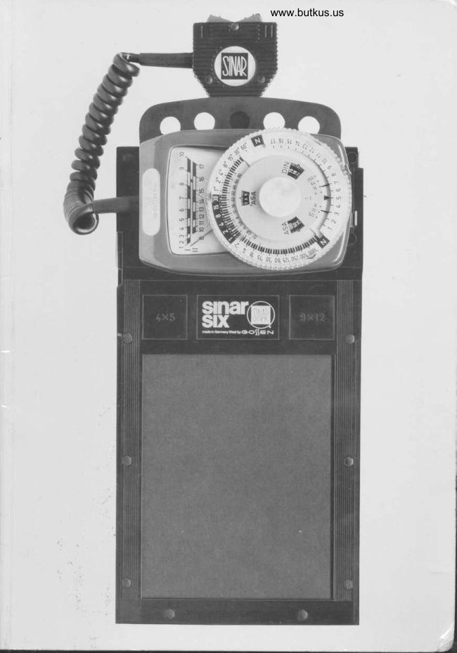
Remove measuring instrument (D) with the photo-resistance probe (C) and the
light-meter cassette (A) from its packing. Assemble the SINARSIX as shown in
Fig. A. Priorto inserting the photo-resistance probe (measuring field C 1, facing to-
wards the camera - lens), open the probe-locking lever (A 1) in the direction of thearrow. To apply the measuring instrumedt to the light-meter cassette, swing the lock-
ing lever (D 1) in the direction of the arrow as far as it will go and hold  it there. The
instrument can now be inserted in the recesses provided for the purpose in the
light-meter cassette. Exert light pressure on instrument and release lever. This will
be locked together automatically by spring pressure.

Manipulations During the Measuring Operation
                           o Prior to inserting the SINAR-
                                        SIX in the camera back, focus the
                                         camera as usual (Fig. 1).


                                               Fig. 1
                            o Set sensitivity of photographic
                                                     material. To this end, the plexiglass
                                                          dial which ensures that there can be
                                no accidental displacement must
                                      be removed first. The DIN or ASA
                                                  indication in the frame (showing
                                         50 ASA) corresponds to the white
                                                       principal indicator  (cf. arrow Fig.2).
                                        Note: The adjustable auxiliary in-
                                                dicators are swung out (as is the
                                                    auxiliary diaphragm scale). To be-
                                           gin with, they need not be used;
                                            their operation is described  in
                                                     Part Two of the Instructions.


                                      Fis.2
View original page 7Page 9 · Read text
Fix probe locking lever and close
             slide for measurement (to avoid
          extraneous light through the
           ground-glass screen) (Fig. 6).


                                Digitally signed by mike
                         butkus
                        DN: cn=mike butkus,mike        o=orphancameras, ou=29,
                          email=mike@butkus.org,
                      c=US
                            Date: 2018.09.06 17:57:44butkus -04'00'
   Fis.6
      o Actuate measuring rocker:
              (left) for poor light (right) for
             bright light.
            Please make sure that the rocker is
           always fully depressed so that the
             protective shield of the photo-re-
             sistance is fully opened (Fig.7).
            Remarks:
          Actuate the measuring rocker
           only with the SINARSIX inserted
            in the camera! (Reason: cf. Part
             Four, Operation.)
           In the ,lower scale range (O to
           about 4 and 1 0 to about 1 2), the
             indicator needle of the CdS expo-
           sure meter rises only slowly. The
             rocker should therefore be depres-
          sed until the needle has come to
               rest; then take a reading.
    Fis.7     lf the SINARSIX has been kept
           unused in the dark for some time,
         the photo-resistance should be
             "stimulated"  first by a brief expo-
             sure to a brighter image area.


      o After measurement, remove light-
            meter from camera (Fig. 8). Insert
             film cassette and expose as indi-
   Fig.8  cated by SINARSIX.
                                                       11
View original page 9Page 10 · Read text
www.butkus.us
 Note:
o The light slide of the SINARSIX may, if desired, be entirely removed from the
   light-meter cassette by depressing its lock (A 3); this is possible specially with came-
   ras provided with a perfectly light-tight protection behind the ground-glass screen.
o  lf the image on theground-glass screen is observedfrom oneside and a measure-
  ment taken at the edge of the field, the shadow of the probe is somewhat displaced
   relative to the position of the marked measuring field. This is, however, insignificant.
  What is decisive for the positioning is the measuring field indicated (C 2).
o In order to ensure easy reading in any position and for the purpose of changing
  formats, the measuring instrument can be separated from the light-meter cassette.
   For release swing lever (D 1) in the direction of the arrow as far as it will go. lf desired,
  the measuring instrument may also be applied to the light-meter cassette rotated
  through 180".
o For transport the photo-resistance probe should always be inserted in the cassette
  housing as far as it will go.
o Please note the battery and zero-point check in Part 4 of the Instructions:
  Operation and maintenance.
View original page 10
Page 11 · Read text
The RAPID Measuring Method
The RAPID measuring method requires some experience in the evaluation of the
subject,  i.e. in the appropriate selection of the measuring point. lt may be applied in
most cases provided that a medium gray suitable for measurement can be found in,
the subject
The area to be measured is best chosen on the subject, better than on the
ground-glass screen   !
The method  is thus based on the visual determination  of the mean gray value of the
subject. To this end; the best procedure is to determine on the subject, with your
eyes half closed and critically comparing other subject areas, the point which is
to be obtained as a medium gray in the picture. Then measure the point
selected in the image and set it as the Exposure Value (EV) directly to the black
Midpoint Indicator (M). The scale is now ready for reading the shutter time (cf.
Fig. 9).


                                                                        Shutter


 Fig.9
View original page 11Page 12 · Read text
www.butkus.us
 This introductory stage of RAPID measurement is based on measuring directly
 with the operating diaphragm of the lens. The aperture isthus preselected, and
 the corresponding shutter time to provide the correct exposure is read directly oppo-
 site the principal indicator of the scale as shown. Shutter times not accurately corre-
 sponding to the principal indicator are compensated by appropriate small corrections
 of the diaphragm setting.
 Remark: The auxiliary diaphragm scale, which provides additional possibilities  in                                     Ithe SINARSIX, is swung out in Fig. 9; its function will be described later in Part Two.


Note:
There is no simpler method of image field measurement with such a comparatively
small risk of erroneous assessment. This method is most exact  if the area of medium
gray in the subject (which is to be reproduced as a medium gray in the picture)  is
determined accurately.
Apply this RAPID measurement to begin with until you are quite familiar with the
SINARSIX; only after successful application proceed to the use of the aids and more
refined measuring methods; the one-point method (Part Three) often provides a
good complement to the RAPID measurement.
View original page 12
Page 13 · Read text
T_


                 Aids


         They provide: more possibilities - further simplifications

       Pre-selection of the Different Sensitivities
       of Photographic Materials                                17

      The Auxiliary Diaphragm Scale                        19

      The Reciprocity Failure Scale


                                                                                         15
View original page 13Page 16 · Read text
www.butkus.us
 The Auxiliary Diaphragm Scale
   Different from the common exposure meters, the auxiliary diaphragm scale of the
  SINARSIX is not coupled to one of the scale functions, but is independently adjusta-
   ble. This arrangement has been specially developed for image field measurement in
   this way.
o Allcorresponding apertures and shutter times are indicated without conversion.
o Measurements can be made with the lens diaphragm wide open, again indicating
  the corresponding diaphragm values and shutter times. This gives the SINARSIX
   effectively higher sensitivity without conversion.
   All corresponding shutter and diaphragm values are indicated using the Recipro-
   city Failure Scales S and X - at a single glance and without conversion.
  The auxiliary diaphragm scale is swung from its concealed into its operative position
   in the direction of the arrow and operated on the following simple principle:
   Set the aperture used for the measurement to that sensitivity indicator whicl refers
   to the photographic material.

                                                      Fig. 13a shows the following ex-
                                                ample:
                               o Aperture used in measuring =
                                                                            f 5.6.
                            o Photographic material used: 50
                                  ASA (set to white principal indica-
                                                               tor).
                                     The aperture 5.6 of the auxiliary
                                           diaphragm scale should be set to
                                                the white principal indicator of the
                                            photographic material employed.
                                     The corresponding apertures and
                                                       shutter times can then be read.


                                            Fig. 13 a
                                                      Fig. 13b shows the following ex-
                                                ample:
                                                                                                lf some other photographic material
                                                                  is employed (e.g. as signalized bY
                                     the red auxiliary indicator), set
                                              the diaphragm used for the mea-
                                         surement to this indicator. The
                                              corresponding values of aPerture
                                    and shutter times can again be
                                                        read.


                                              Fis. 13 b
                                                                           19
View original page 16Page 17 · Read text
Note:
a With the SINARSIX measurements can betaken with the diaphragm of the lens
   fully open or with the working diaphragm.


  Advantages of measuring with the diaphragm open:
o The SINARSIX becomes "faster" for border-line cases (interiors, macro-pictures,
   dark subjects, etc.)


  Advantages of measuring with the working diaphragm:
a In measurements near the edge of the field of the lenses (shifts, swings,-
   wide-angle), the vignetting by the lens mount is measured correctly as well; this
  depends on the diaphragm employed. (The lens mount is known to have a stronger
   vignetting effect when the diaphragm  is open than when it is closed.)
     It is therefore highly recommended to measure with the working diaphragm in such
  cases in order to avoid overexposures.
o Intermediate shutter times should not and often cannot be set. Intermediate
  exposure values should therefore be set by means of the aperture which is much
  more suitable for this purpose.
o The control lever of the auxiliary diaphragm scale is provided with a cup to avoid
   accidental movement of the plexiglass dial when it is operated.
   In turn, it is only half the height to prevent  it from being inadvertently shifted when
  the plexiglass dial is rotated.
o  lf on taking a measurement directly with the working diaphragm, the correspond-
  ing apertures and shutter times are of no interest, swing the auxiliary diaphragm
  scale in the clockwise direction back to its covered end position. (Shutter times not
  accurately corresponding to the principal indicator are compensated by appropriate
  small corrections of the diaphragm without using the auxiliary scale.)
  Never use guess work to correct results obtained; this would inevitably lead to
   incorrect results.
View original page 17Page 18 · Read text
www.butkus.us
                      The Reciprocity
                             Failure Scale
                                       The separate calculation of the ex-
                                                 tension of exposure time necessary
                                          because of reciprocity failure be-
                                  comes superfluous with the Sl-
                                  NARSIX by using the appropriate
                                               interchangeable scales.
                                 The SINARSIX is provided with
                                       three interchangeable  plexiglass
                                                          dials:
                                     O Dial N bears the usual linear
                                                    shutter time sequence.
                                    o Dial S bears a shutter time se-
                                         quence taking care of average re-
                                               ciprocity failure; for color and
                                         black-and-white material- (data
                                            without guarantee).
                                           Fig. 14 I  Dial X provides space for mark-
                                         ing your own reciprocity failure
                                            according to individual manufac-
                                                      turers' data. (For marking, remove
                                                                circlip. The metal scale can then be
                                         removed from the plexiglass disk.)
By themselves and, more particularly, in combination with the auxiliary indicators
showing the Exposure Values of photographic materials of different sensitivities,
these Reciprocity Failure Scales vastly simplify the determination of shutter times.
It is recommended to mark on the dial involved the correction  filters frequently re-
quired for color exposures. (Cf. Fig. 14; data without guarantee. Note manufacturer's
indications.)   rj


                                                                                   21
View original page 18Page 19 · Read text
ar
                               \)
       More Advanced
     Measuring Technique


Terminology                                                 25

Contrast Value (CV) of Photographic
and Copying Material                                      26

Subject Types                                                  29

Two-point Measuring Method                           31

One-point Measuring Method                       33

Measurement of a G ray Card                        35

General Notes on the Measuring Methods
View original page 19Page 20 · Read text
www.butkus.us
Terminology
 (also cf. back cover D 7, 10, 11, 12)


The terms used in applying more advanced measuring techniques to professional
equipment demand clear organisation with internationally  applicable abbreviations.
Where practicable, these abbreviations are repeated in the text of these Instructions.
L = Light Value = any figure of the SINARSIX indication rangeEV : Exposure Value = the light value employed for exposureM : Midpoint = calibration point of SINARSIX
CV = Contrast Value = difference between brightest and darkest areas     (CVS : Contrast Value of Subject; CVI : Contrast Value of lmage)      Contrast Value Limitl = limit of CVI (right : bright side; left = dark side)


rAt these limits, detail is as a rule just visible.
                                                                   25
View original page 20Page 21 · Read text
Contrast Value (CV) of Photographic and
 Copying Material
  We strongly recommend checking and, if necessary, limiting the Contrast Value (CV)
   since the exposure margin is known to shrink as the contrast to be reproduced
            i ncreases!

  As Contrast Value is the next important factor for good exposures after the sensi-
   tivity of photographic material, the SINARSIX has a special scale (D 13) forthis
   purpose. Please note that the numbers on this scale are alternatively located at left
  and right in order to achieve better legibility.
  The indicators (D 12) showing the limit of Contrast Values of lmage can be adjusted
   by means of the control lever (D 11).
  As the SINARSIX measures the image, the Contrast Value (CV) of the lmage (CVl)
   is determined. This is generally lower than that in the subject itself because of
   scattering of the light.


  The following limits of the Contrast Value of lmage should be observed in
   practice (deliberate effects always excepted). These data are to be regarded as
  guiding values, in particular for color pictures. However, it is advisable to observe
   these values, and double them for black-and-white pictures.

  For projection and viewing
O For transparencies (slides) up to 1 :250, for prints up to 1 :32.
o The CVI of negatives should also be adjusted to no higher than 1:250.

  For reproduction and filing for future uses of all kinds
o Reversal positives and negatives up to 1 :16.
o 1:16 is recommended as the mean CV of thelmagefor colorpicturesfor
  reproduction, although a higher Contrast Value can be reproduced with almost all
   materials. The actual bottleneck of good reproduction, however, lies with the reflec-
   tion print, especially as an original for printing. Different from amateur shots, profes-
  sional pictures are as a rule made for further use, the kind of use frequently not
  known at the time when a picture is taken. This is why it is recommended to keep
  the CVI within such limits that further use is ensured, if possible, without correc-
   tions.
  26
View original page 21Page 22 · Read text
www.butkus.us
Correction of Excessive Contrast Value
(excluding planned special effects)

Where a check measurement of the brightest and darkest picture areas indicates
a Contrast Value of lmage larger than desired, brighten the shadows to the desired
values using known expedients, or apply or wait for more diffused lighting.
It may also be considered whether the two limit values measured may possibly be
outside the good Contrast Value Limits.

Caution: Take a new measurement if lighting changes!
View original page 22
Page 23 · Read text
I


   Group 1. Symmetrical


Group 2. Unsymmetrical


Group 3. Gray-in-Gray
View original page 23
Page 24 · Read text
www.butkus.us
Subject Types
For the refined measuring methods now to be described-and for the appropriate
assessment of a subject in general-we must have at least a rough idea of the kind
of brightness structure in a subject.


Before proceeding to taking a measurement, we group subjects in one of the
three following types: -
Type 1 - Subjects having a substantially symmetrical brightness structure           (the great majority of subjects, also pictures taken against the light,
             largely belong to this group)
Type 2 - Subjects having an unsymmetrical brightness structure (e.g. high            key,distant views, snowscapes, etc.; or low key, forests, paintingB of old
            masters, etc.)
Type 3 - Gray-in-graysubjects


This division will be made automatically  after a short while. According to the type of
subject found, we select the measuring method to be applied, viz.:
two-point method for type 1 (symmetrical brightness structure);
one-point method for type 2 (unsymmetrical brightness structure);
measurement of a Gray Card (or RAPID Measuring Method) for type 3 (gray-in-
gray).
The measuring methods applied to types 1 and 2 also incorporate in the measuring
process the Contrast Value of the lmage CVI so important to the best utilization of
the exposure range.
View original page 24Page 26 · Read text
-T-
                                             www.butkus.us
       Two-point Measuring Method

                                                                                                                            1               for subjects having a symmetrical brightness structure, Type

           As the name implies, two points are measured in this process, viz. the brightest
         AND the darkest image areas in which detail is just visible.

             This measuring method Provides:
        o the Contrast Value of the lmage (CVl) and
       o the associated mean Exposure Value (EV)

              Procedure:
       o Measure the brightest picture area (in the illustration = 7).                                                                                   "bri0ht" (at             Set result by rotiting the plexiglass dial to the red limit value indicator
                 right), cf. Fig. 15a.
       o Then measure darkest picture area (in the illustration = 3).
              Set result to red limit value indicator "dark" (at left) as follows:
             Grasp the plexiglass dial as per Fig. 16 (without disturbing the previously.set  limit
              value "bright" 11), forcethe control lever of the CVI scale (D 11) againstthe plexi-
               glass dial iritf' your thumb, and rotate both until the measured dark Light Value (3)
                   is opposite the ied limit indicator "dark" (left). This gives a positive indication of the
             resuiting Contrast Value for the measured 1:16 lmage and the associated mean
             Exposure Value (EV) 5 opposite the black Midpoint indicator M'
           The lens aperture used for the measurement is then placed opposite the appropriate
                sensitivity indicator, whereupon the various combinations of aperture and shutter
             time can be read off.
       Note:
       o Measure bright picture area first, dark area afterwards.
              Dispense with extreme values for the bright and dark picture areas, e. g. with lamps,
              sun, windows, or dark holes, such as tunnel mouths, etc. (This also applies to the
             one-point method and particularly to against-the-light exposures.)

          Recommendation:
            Observe the subject to be taken with your eyes half closed and determine which
               brightest picture area-and then which darkest area-should still show detail!
             Gorrect: cf. Fig. 15a.
            Caution ! Beware of one-sided measurement, e.g. of bright area with just visible
                  detail, dark area gray with PlentY of detail. This would result in failures. Incorrect:
                 cf. Fig. 15b.
             With iome care, you may measure, instead of the brightest and darkest picture areas
                that should still show detail, a medium bright and a corresponding medium dark area,
              but accurate determination of these measuring areas pre-supposes more experience
             than the determination of limit values. The resulting CVI here applies only to the
             range measured.
             ThJtwo-point method is the most accurate procedure because on the one hand two
             measuring points must be determined, and experience shows a reduction in evalu-
              ation errors; on the other hand, errors in evaluation on one side, if any, are
              halved by the determination  of the mean value. Moreover, the determination of the
              Contrast Value of the lmage (CVl) in the two-point method brings in for assessment
             a further important factor in accurate exposure.
                                                                                                  31
View original page 26Page 30 · Read text
www.butkus.us
 Measurement of a G ray Card
   for gray-in-gray subjects, Type 3

  The measurement  of a Gray Card is designed to substitute the stable tone value of a
  gray card for a subject, the tone values of which are difficult to determine.This
  method can also be applied in all cases where  it appears to be more advantageous than
  one of the other measuring methods.

  This measuring method provides the Exposure Value (EV).
  To perform the method, two KODAK NeutralTest Cards are supplied with the SINAR-
   SlX. Apply to KODAK dealers for further Neutral Test Cards  if required.

   Procedure:

   Place the Neutral Test Card in the subject space so that it receives the same light as
  the subject.

O Where three-dimensional subjects are involved, the subject contrast is affected
  by the lighting contrast. In order to include the lighting contrast in the measurement
  as well, KODAK prescribes the following procedure:
  Hold the card close to and in front of the subject, turning the card so that  it faces half-
  way between camera and main light. Do not allow your shadow to affect the reading
   (Fig. 19).
   ln daylight deduct %li1ht value from reading. E.g.: reading 8, EV :7Tz'
  Forvery bright;ubjects, add % light value to reading. E.g.:reading 13, EV = 13%.
   For very dark subjects, deductTzlight value from reading. E.g.: reading 7,EV 6y2.

  With two-dimensional subjects (reproductions,  etc.)  :
   Place the card parallel with the subject. The Exposure Value obtained should be
   placed opposite the Midpoint indicator M (cf. Fig. 20).
  The lens aperture used for the measurement  is again referred to the appropriate sensi-
   tivity indicator and the corresponding aperture and shutter times can be read.


  Note:
  Where the light is poor (indications below 5), measure with the white side of the
   Test Card. In this case, deduct two units from the Light Value obtained. By way of
  example: obtained 6, set 4 = EV.
     lf theTestCardarea  is too smallfor measurement,place  itthe same way asdescri-
  bed above (in the same light as the subject!) and look for a corresponding  larger
   area of the same brightness in the subject by comparison (half closing your eyes).
  Then measure this subject area.
                                                                      35
View original page 30Related documents and language editions

From the M. Butkus archive. Original publisher and archive notices are retained.
Check the model and edition against your equipment.
PDF verified 2026-10-10.