Film cameras
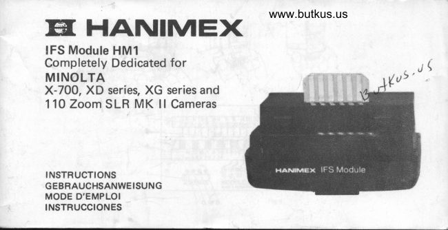
Hanimex IFS Module HM 1 User manual
User manual for Hanimex IFS Module HM 1. 45 pages in German, French, Spanish. Read the original PDF, download or print a copy without registration.
45 pagesGerman, French, Spanish2.1 MB PDF
Loading your manual…Open PDF directly
Document details
- Brand
- Hanimex
- Model / document
- Hanimex IFS Module HM 1
- Document type
- User manual
- Language
- German, French, Spanish
- Pages
- 45
- File size
- 2.1 MB
- Category
- Film cameras
- Document date
- Not specified in catalog
Search available document text
Find a term, then jump to its page in the original PDF. Image-only pages may not be searchable; check the PDF for exact wording and diagrams.
Page 1 · Read text
www.butkus.us
Eil HAI\IIMEX
IFS Module HMl
Completely Dedicated for
MINOLTA
X-700, XD series, XG series and
11O Zoom SLR MK ll Cameras


INSTRUCTIONS
GEBRAUCHSANWEISUNG
MODE D'EMPLOI
INSTRUCCIONES
View original page 1
Page 5 · Read text
LOADING BATTERIES, POWERING UP        the yellow dot (Y) and the second position
 ETC                                                 at the green dot (G) select autornatic opera-
  Please read the instructions of the Flashgun        tion. The third position at the white dot (Wl
  proper.                                              gives f ullpower manual operation for all
                                               cameras or TTL auto flash for the X-700 MOUNTING                                                   while the fourth position at the blue dot (Bl "  Please ensure that the knurled clamp ring is                                                       gives one-sixteenth power manual operation turned upwards fully before entering the foot                                                      for such applications as motor drive.  into your camera's hot shoe. The calculator
   (f ig.   ) is always towards the rear of the
 @mera. Push the foot home fully and clamp    AUTOMATIC OPERATION
   f irmly with the clamp ring.                  When the  f lash is fired, a sensor in the module
                                                        integrates the light being ref lected from the
 AUTO/MANUAL SE LECTOR SWITCH           subject and when this reaches a predetermin-
  Figure 4 shows the controls and calculator.       ed value, the series thyristor switches off the
 The Auto/Manual switch (1) allows you to                f lash-tube. This has two great benefits. First-
 choose the mode of operation. The  f irst posi-       ly, as long as the subject is within the flash-
 .tion of the switch (as depicted in  f ig. 4) at        gun's range, you get the correct exposure re-4
View original page 5Page 6 · Read text
www.butkus.us
gardless of the  f lash to subject distance; and     USING THE CALCULATOR
secondly, any unused charge is saved so re-       See Figure 4. The top scale (5) called the
ducing the demand on the batteries.               'Distance Scale' is part of the  f lash gun
There are two predetermined exposures cor-       proper. Since the IFS modules  f it more than
respondin gto  t 12.8 100 ASA (Green setting)     one HANIMEX IFS Flashgun the figures on
and f/5.6 100 ASA (Yellow setting).                 this scale may be different from the one you  ''
                                                   have. However the principle of operation  is
TTL FLASH OPERATION                       the same.
With the X-700, some of the light entering       a) Always set the index mark (9) of tne
the camera's lens is used to compute the ex-          aperture slide {8} to the speed of the
posure and turn the  f lash off immediately the         film you are using and which you have set
exposure is completed. This not only gives the      on your camera's film speed dial. In figure
advantages of Auto operation and economic        4 it is shown set to 100 AsA (DlN 21).
battery usage, but also automatically takes       b) Move the Distance scale (5) so that its
into account such things as f ilter factors and          index mark (O) is aligned with that one of
ambient lighting.                                    the marks (T, S, W1, or W2) which agrees
View original page 6Page 7 · Read text
with how you have set the zoom head of           In the example you can see that automatic
          your flash gun.                                  operation  is possible up to a distance of
            In figure 4 it is shown at W1.                  30 feet (9 metres) with the green auto
                                                                     setting and 100 ASA film.
      The calculator is now set up and you can see      NOTE. The distance indicated is for aver-
        the following:                ,                        age conditions. Light absorbing subject or'
            i) lf the Auto/Manual switch (1) is set to the       backgrounds will reduce this distance.
           green AUTO position (G) then looking         Bounce flash operations will reduce it
         below the green stripe (7) you can see the         greatly.
           correct aperture to use (with that auto set-      ii) lf the Auto/Manual switch (1) is set to the
           ting and your film), on the white  f igures        yellow auto position (Y), then you look
            (3) of the aperture scale. In the example       below and above the yellow stripe (4) for
            this is t12.8.                                   the correct aperture and ma'ximum dis-
          Looking above the green stripe (7) and          tance. In figure 4, the correct aperture
        fo||owingtheIineupwardsyoucanseewou|dbef/5.6andthemaximumrange
'          the distance in feet or metres beyond          about 15 feet or 4Tz metres.
         which automatic operation is not possible.   iii) lf you are using TTL flash photography       -    6                                                                                                                                                                                                                                                                                                                                                                                                                                                                                                                                                                                                                                                             i
                                                                                                                                                                                                                                                                                                                                        I
View original page 7Page 8 · Read text
www.butkus.us
   with the X-700, you will have the Auto/          should set. In this case, find the distance
   Manual switch (1) in the white TTL posi-        on the distance scale (5), follow the near-
   tion (W) and will want to know that you           est line down to a while, black or coloured
   are within the maximum flash to subject           stripe and then to the correct aperture on
    distance. First find the aperture you are           the white  f igures (31 of the aperture scale.
    using on the white  f igures (3) of the aper-                                f n  f igure 4, Ior example we are shooting
   ture scale and then follow upwards via a           at a flash to subject distance of 10 feet
   white, black or coloured stripe and line          (3M) we would follow the line and stripe
   above up to the distance scale (5) where        down to f/8.
   you can read the maximum distance. In       v)  lf the Auto/Manual switch (1) is set to the
   the example depicted, if you were at  f 14            right hand, blue manual position (B), you
   you could shoot out to 20 feet (6 Ml.              are shooting at reduced power and need a
iv) lf the Auto/Manual switch (1) is set to the          larger aperture. Follow down from the
   whtie manual position (W) and your                flash to subject distance to the blue figures
   camera is in the manual mode, usually,              (2) on the aperture scale. In  f igure 4, for a
   you have a subiect at a certain distance                         f lash to subject distance of 1O feet (3M)
   and wish to know what aperture you          we find  f 12.
                                                                     7
View original page 8Page 9 · Read text
5
TTL AUTO FLASH WITH THE X-7OO IN      e) Switch on the flashgun and wait until the
PROGRAM MODE                                                                           f lash ready signal is given by the  f lash
a) Make sure that the basics are set.                 red bar at the figure 60 in the viewfinder
    "   The film speed setting on the camera        or by the 'Ready' light on the flashgun.
    *   Theis correct.camera is switched on.                     fl  NoteFocus,(iv)check that you are in range, and    *  The lens in use is the MD type.              shoot. Notes (v), (vil
       The plus/minus exposure correction    NOTES
             is at '0' unless otherwise desired.                 i) The +/- sign in the viewfinder will not
       Note (i)                                      blink to warn you if an exposure correc-
b) Set the mode selector on the camera              tion is set if the flash is ready.
    to'P'                                                               ii) Locking device is only  f itted to new typec) Set and lock the lens at minimum aper-      MD lenses.
   ture (highest f/no.) Note (ii)                   Note also that the green 'P' in the view-
dl Set the Auto/Manual switch (1) at the                          f inder will blink whenever you are not at
   white TTL position (W) Note (iii)             minimum aperture.
View original page 9Page 10 · Read text
www.butkus.us
iii) You may also set to the blue posit'ion           vi) The led at'60'will blink rapidly for
    since the programme mode will auto-           about 1 second if the shot was within
    matically switch the  f lash to full power.           range. lf it goes out, get nearer the
iv) Viewfinder information is given only if it          subject or choose a larger aperture and
      is switched on by touching the camera            switch to 'A'.       gulkub u)   shutter button. lt will remain on for about
   15 seconds after you lift your  f inger.        TTL AUTO FLASH WITH THE X.7OO IN
                                                 PR IOR ITY MODEvl In the Program mode the X-700 auto-      APERTURE
    matically sets the aperture somewhere        Use Aperture Priority rather than the Pro-
   between f/8 and the maximum aperture of    gramme mode when you wish to use a certain
   the lens in use depending on the ambient      aperture for depth of field control or for dis-
    lighting. lt then indicates the chosen aper-      tances outside the P range.
   ture at the bottom of the viewf inder. Use     a) Make sure the basics are set just as in P
    this value as described in USING THE          mode TTL.
  CALCULATOR to determine the maxi-      b) Set the mode selector to 'A'.
  mum range and check this against the        c) Set the aperture desired on the lens ring.
    lens focus distance scale.                      Note (i)
                                                                    9
View original page 10Page 11 · Read text
d) Set the Auto/Manual switch (11 to either   AUTO FLASH WITH XD, XG, X-7OO & 110
     the white TTL position (W) or the blue      Zoon SLR MK. ll
    TTL setting (B). Note (ii)                a) Ensure that the camera is switched on, the
  e) Switch on the flashgun and wait till the           film speed is set and that exposure control
           f lash is ready as described  f or the 'P' mode.            is in the normal position.
  f) Focus and shoot. Note (iii)                 bl Set the X-7OO shutter dial to any position  r.
  Notes                                         between 1 and 1000. Set all others at their
     i) See USING THE CALCULATOR for             'A'setting for normal auto exposure
     checking the range with the aperture you        photography. Note (il
     have set.                                                 cl  Set the Auto/Manual switch (1) to either
    ii) The action is the same at either setting           the yellow setting (Y) or the green setting
     except that the range is considerably              (G). Ttre green setting is usually the best
     shorter on the tslue setting.                     except for close-ups or when using a slow
   iiil The l.e.d. at'60' will blink rapidly for               lens.
    about a second if the shot was in range. lf     d) Set the lens aperture ring to the appro-
        it goes out choose a larger aperture or get         priate figure as determined by the film in
     closer to the subject.                             use and your autoflash choice. For 100
10
View original page 11Page 12 · Read text
www.butkus.us
  ASA (DlN 211 it is t12.8 for the green set-   MANUAL F LASH PHOTOGRAPHY
    ting or f 15.6 for the yellow setting. For        Please follow the directions for Auto Flash,
   other film speeds please see USING THE      but set the Auto/Manual switch (1)to the
  CALCULATOR. Note (ii)                   white position (W) or to the blue position (B)
el Switch on the flashgun and wait till the        for reduced power
       f lash ready signal appears in the viewf inder.     In manual photography correct exposure  is
fl  Focus and shoot.                            obtained by choosing an aperture to match
Notes                                           the  f lash to subject distance as determined by
  i) The shutter will be set automatically to       the calculator or by use of the'Guide Num-
   the X-synch speed when the  f lash is ready.     ber'. For Guide Number details please refer to
 iil The larger the aperture the less the power     your  f lashgun instructions.
   taken from the  f lash at a given distance
   and hence a faster recycle time. Alterna-
    tively the larger the aperture the greater
   the range.
   MINOLTA is a registered trade mark of MINOLTA CAMERA COMPANY LTD.
                                                                             11
View original page 12Page 13 · Read text
INTERNATIONAL LIMITED WARRANTY
                   rcOEL IFs MODULE HMl

This product  is warranted to be free from defects  in workmanship and materials for a period of 12 months from the
date of purchase.  lf  repairs are necessary during this period, because of any such clefects, then at our option the
product will be either repaired or repltred  {ree of charge with an equivalent product. SATISFACTORY PROOF OF
THE PURCHASE DATE MUST BE FUBNISHED AT THE TIME OF NOTIFICATION OF THE DEFECT FOR ANY
CLAIM UNDER THIS WARRANTY TO BE ENFORCEABLE.
This warrantv  will become  invalid  if the product has been subjected to modification6, abuse, improper treatment
and/or  if any defect is caused by repairs made by any unauthorised  person.There  are no warranties express or implied
except for those which are stipulated herein and those which are implied and cannot Fe excluded  in law provided that
in those countries and states where  it is possible to limit the implied warranties of rnerchantability and of fitness for a
particular purpose to the duration of this warranty they shall be regarded as being so limited
This warranty does not cover batteries, damage caused by batteries,  film, damage to film,lamps, flashlamps or flash'
butbs. where applicahle. FURTHEBMORE, INCIDENTAL AND CONSEOUENTIAL OAMAGES OF ALL KINDS
WHATSOEVER ARE EXCLUDED IF AND TO THE EXTENT TO WHICH IT IS POSSIBLE TO DO SO IN LAW.
Returns must not contain batteries, should be properly packaged, and prepaid to Vour nearest Hamimex branch or
alternatively through your dealer.
This warranty gives you specific  legat rights and you may have additional rights and remedies which either cannot be
exclucled or timited In law or which have not been excluded or limited by the terms of this warranty and which may
vary from state to state and from country to country as, for instance, some states in the United States of America do
not allow exclusion or limitation of incidental or consequential damages and in France this warranty cannot preclude
rhe operation of article '1641 ancJ other articles ot the French Civil Code in relation to latent defects.
View original page 13Page 14 · Read text
www.butkus.us
E INLE ITUNG                                    Blitzbereich die volle oder 1/16 Blitzleistung
Das HANIMEX IFS-Modul HM1 ist fuer alle     zu verwenden.
HAN IMEX  I FS-Blitzgeraete passend und         Bei der X-700 steuert das HM1-Modul das den
liefert fuer folgende 35mm Spiegelreflex-        Film erreichende Licht und erlaubt den Vor-
Kameras die Multifunktion: Minolta XE,            teil der TTL Autoblitzfotografie, entweder
XG und X-700. Es                         ausserdem                    arbeitet                                     mit       durch                                   "PROGRAMM" - Steuerung oder durch                    bei                     Minolta                          110 ZoomVollmultifunktion                                            Automatik.
Spiegelreflex-Kamera Mark  I l.                                   EINSETZEN DES MODULS K.Abb. I, 2 + 3)Fuer alle erwaehnten Kameras wird bei Ver-                                         Das Blitzgeraetegehaeuse  (13) hat zwei Rip-wendung des HM1-Moduls und des  I FS-
                                       pen (12t. , auf jeder Seite eine, in dessenBlitzgeraetes automatisch die Blitzsynchron-                                                  Schlitze (10) das Modul eingeschoben wird.zeit eingeschaltet und im Sucher angezeigt,
                                             Unter besonderer Beachtung der Ecken (141soba ld die B  I itzbereitschafts -Anzeigelampe
                                       und leicht angewinkelt, schieben Sie dasaufleuchtet. Nunmehr besteht die Moeglich-
keit zwischen zwei Automati k-Thyristor        Modul in die vorgesehene Fuehrung (12) mit
                                                der aufgesetzten Zunge (1 1 ) gerade nach obenBlitzbereichen zu waehlen, oder im manuellen
                                                        in das Blitzgeraetegehaeuse  ein. Der feste Sitz  _
                                                                       13
View original page 14Page 15 · Read text
des Moduls ist gesichert, wenn dieses durch   AUTO/MANUE LL.WAEH LSCHALTE R
  ein Klickgeraeusch einrastet.                 Abb. 4 zeigt die verschiedensten Einstellungen
                                               mit dem Schieberegler. Mit dem Auto I
                                                  Manuell-Schalter  (1) ist es moeglich, verschie- EINSETZTEN DER BATTERIEN, BLITZEN                                          dene Einstellungen zu waehlen. Die erste Posi-
                                                                                                                                                                                                          1'  usw.                                              tion am Schalter (wie in Abb. 4 angegeben)  Bitte lesen Sie die Hinweise ueber das Blitz-                                           beim gelben Punkt (Y) und die zweite Posi-
  geraet sorgfaeltig.                                                    tion am gruenen Punkt (G) entsprechen der
                                             Automati k-E   i nstel   I u ng.
 BEFESTIGUNG                              Die dritte Position, weisser Punkt (W), liefert
  Bitte stellen Sie fest, ob der Sicherungsring      volle Blitzleistung bei manueller Einstellung
  (6) ganz nach oben gedreht ist, bevor der        fuer alle Kameras oder fuer TTL Auto-
  Geraeteschuh auf die Kamera gesteckt wird.     Blitz bei X-700 waehrend die vierte Position
  Der Schieberegler (s. Abb. 4) zeigt stets zur     durch den blauen Punkt (B) bei manueller
  Kamerarueckseite. Mit dem Verriegelungsring    Einstellung 1116 Blitzleistung fuer motor-
  wird das Blitzgeraet and der Kamera befestigt.   getriebenen F ilmtransport  liefert.
74
View original page 15Page 16 · Read text
www.butkus.us
      AUTOMATI K.E INSTE LLUNG           TTL BLITZEINSTELLUNG
        Sobald der Blitz abgegeben wird, erhaelt der    Bei der X-700 wird ein Teil des Lichts vom
         eingebaute Sensor ein ref lektiertes Blitz-       Kamera-Objektiv aufgenommen. Der Com-
          signal und steuert durch den Thyristor die     puter bestimmt die Belichtung und schaltet
         Lichtmenge, die fuer die Aufnahme erforder-   gleichzeitig das Blitzgeraet ab. Dies ist ein
                                                                                                                                                                                                                         {'          lich ist. Es wird nur so viel Licht abgegeben,    Vorteil der Blitzautomatik, spart Batterie-
        wie fuer die Blitzaufnahme im vorgesehenen   strom und beruecksichtigt Filterverlaen-
         Entfernungsbereich  erforderlich  ist, so dass     gerungsfaktoren und schwierige Lichtverhaelt-
          gleichzeitig die nicht gebrauchte Energie         nisse.
         gespeichert und somit auch Batteriestrom                                   GEBRAUCH DES SCHIEBER EGLERS         gespart wird.                                                          k. Abb. 4)        Es stehen wahlweise zwei Blendeneinstel-                                                     Die obere Skala (5) ist die Entfernungstabelle.         lungen, F 12,8 (DlN 211'lOO ASA) gruene                                                  Die IFS-Module sind fuer eine Reihe von        Markierung und F15,6 (DlN 21l1OO ASA)                                     HAN IMEX  I FS-Blitzgeraeten einsatzbereit.            gef be Markierung zur Verfuegung.                                                     Die Markierungen auf der Geraeteskala sind   .

                                                                                                                          r.5
l-
View original page 16Page 17 · Read text
daher von Modul zu Modul verschieden, die     erfolgt. Es ist folgendes abzulesen:
Handhabung jedoch ist in jedem Fall die         l)    Wenn der Auto/Manuell-Schalter (1) in
gleiche.                                                  Position gruen (AUTO (G) gestellt
a)    Die Markierung (9) auf der Blenden-           wurde, ist oben das gruen markierte
       skala (8) ist stets der Filmempfind-            Feld (7) zu beachten und die darunter
                                                                                                                                                                                                              {'                       I ichkeit gegenueberzustellen, dessen            befindliche Blende zu waehlen. lm
       Filmmaterial sich zur Zeit in der                 Beispiel ist es Blende F 12,8.
      Kamera befindet. Die Abb. 4 zeigt die         Ein Blick nach oben, ueber der gruenen
       Einstellung DIN 21 (ASA 100).               Markierung l7l, zeigt lhnen die Entfer-
                                                                                      Fuss-b)    Die Entfernungsskala (5) ist einer              nungsskala in Meter - und      der Markierungen  (6) T, S, Wl oder          Angaben und welche Automatik-
    W2 gegenueberzustel len, entsprechend          Einstellung fuer einen Entfernungs-
      der Ei nstellung am Bl itzgeraet-Zoom-           bereich bis zu 9 Meter (30 Fuss) unter
      Kopf. In der Abb. 4 ist die Einstellung        Anwendung der gruenen Autoeinstel-
    W1 markiert.                                   lung bei DIN 21IASA 100 Film vorge-
Mit dem Schieberegler ist die Einstellung             sehen ist. HINWEIS: Die Entfernung-
View original page 17Page 18 · Read text
www.butkus.us
                                                                       zu ermitteln.       sangabe entspricht einer ca. - Entfer-           groesste Blitzentfernung
      nung. Dunkle Motive, wie auch schwar-          Stellen Sie die Blende fest, die einge-
       zer Hintergrund reduzieren die                      stellt werden soll, s.Abb. 4, Position (3)
       Blitzentfernung. Das gleiche trifft fuer          weiss (W). Nunmehr besteht die Moeg-
       direktes Blitzen zu.                                 lichkeit, zwischen der weissen, schwar-
ii)    Wenn der Auto/Manuell-Schalter (1) in        zen oder der farbigen Markierungslinie
       Position gelb AUTO (Y) gebracht             nach oben die groesstmoegliche Entfer-
      wurde, gibt das gelb markierte Feld (41        nung auf der Entfernungstab. (5) zu
      nach unten die Blende und nach oben           ermitteln. lm Beispiel entspricht der
      den Entfernungsbereich  an. In Abb. 4          Entfernungsbereich 6 Meter (20 Fussl
         ist die Blende F/5,6 und die Hoechst-           bei Blende F 14.
      entfernungist 4% Meter (15 Fuss).          ivl    Wurde der Auto/Manuell-schalter  (1 )
iii)    Bei Verwendung der TTL Blitzfoto-            auf die weisse Markierung (W) manuell
       grafie mit der X-700 ist der Auto/                 gestellt, und die Kamera  ist auf manuell
       Manuell-Schalter (1) in die weisse TTL          geschaltet, haben Sie bereits eine feste
       Position (Wl zu bringen, um die               Entfernung zum Aufnahmeobjekt

                                                                           17
View original page 18Page 19 · Read text
ermittelt. Stellen Sie nun noch die              blaue manuelle Position (B), wird die
dazu gehoerige Blende fest, indem Sie           Blitzaufnahme mit verminderter Licht-
auf der Entfernungsskala  (5) mit der              leistung gemacht und es ist eine groes-
angrenzenden Linie nach unten eine             sere Blende einzustellen. Folgen Sie
Verlaengerung ziehen, die zwischen der         von der Entfernungsskala nach unten
weissen, schwarzen oder der farbigen            auf die Blendenskala, bis zu den blau   I'
Markierung liegt. Nun koennen Sie die          markierten Blendenzahlen  (.2t'. ln Abb.
richtige Blende auf dem weissen Feld         4 ist der Blitzentfernungsbereich  3
(3) ablesen. In Abb. 4 wurde z.B. ein           Meter (10 Fuss) bei Blende Fl2.
Entfernungsbereich von 3 Metern (10
Fuss) festgelegt, so dass mit der Linie   TTL AUTO BLITZ MIT DER X.7OO BEI
                              ,,PROGRAMM" _ EINSTE LLUNGnach unten fuehrend die Blende einen
Wert von F/8 ergibt und einzustellen    a)    Pruefen Sie, ob die folgenden Ein-
ist.                                               stellungen vorgenommen worden sind:
                                            * Die Filmempfindlichkeit ist richtiglst der Auto/Manuell-schalter  (1 ) ganz
nach rechts geschoben, d.h. auf die                           ei ngestel   I t.
View original page 19Page 20 · Read text
www.butkus.us
      * Die Kamera ist eingeschaltet.                  signal bei Nr. 60 im Sucher (oder durch
       * Das verwendete Objektiv entspricht          die Bl itzbereitschaftslampel angezeigt
         der MD-Serie.                                 wird, (s. Hinweis iv).
      * Die +/- Betichtungskorrektur  ist in    f)     Der Entfernungsbereich wird ermittelt.
          Position "0" eingestellt.                     Die Aufnahme kann gemacht werden,
          (s. Hinweis:  i)                                               (s. Hinweis v und vi).                                       4'
b)     Der Waehlschalter an der Kamera ist
        in Stellung "P" zu bringen.            HINWEISE
c)   Am Objektiv  ist die kleinste Blende              i)     Wurde eine Bel ichtungskorrektur durch
                  ( hoechste Zahll ei nzustel   I en.                      die +/- Anzeige im Sucher vorgenom-
         (s. Hinweis:  ii)                             men, wird dies nicht durch ein Warn-
d)     Der Auto/Manuell-Schalter (1) ist auf            blink-Signal angezeigt, obwohl die
                                                                                                                                                                                                 I itzbereitschaftsanzei ge auf leuchtet.       die weisse TTL Markierung (W) zu                B
        stellen, (s. Hinweis  iii).                                  iil     Die Sperrmechanik  ist nur fuer die
e)     Das Bl itzgeraet ist einzuschalten.              neuen M D-Objektive vorgesehen.
      Warten Sie, bis das Blitzbereitschafts-           Beachten Sie, dass das gruene "P" im

                                                                            19
View original page 20Page 21 · Read text
Sucher blinkt, wenn nicht die kleinste             u ntersch iedl ichen Lichtverhaeltn issen.
      Blende eingestellt worden ist.           Am unteren Teil des Suchers wird die
iii)    Es kann auch die blaue Einstellung              ermittelte Blende angezeigt. Benutzen
     vorgenommen werden, da durch den            Sie diesen Wert, wie in GEBRAUCH
                                        DES                                             SCH                                                                                                                                                                                                    I E BEREG LERS beschrieben,                           Schalter                                 automatisch    "PROGRAMM"                      -                                                                                                                                                                                                              {'                                                             groesstmoeglichsten                          volle                                     um                                                 den                                Lichtleistung            Blitzgeraet auf      das                                                             Entfer-
      umgeschaltet wird.                            nungsbereich zu ermitteln und verglei-
iv)    lm Sucher wird die Anzeige nur dann         chen Sie diesen mit der Entfernungs-
       sichtbar, wenn der Ausloeser leicht                   s kala.
      beruehrt wird. Die Anzeige verbleibt  vil    Die LED Anzeige "60" blinkt fuer
      noch etwa 1 5 Sek, nachdem der              etwa 1 Sek, wenn fuer die Aufnahme
      Ausloeser wieder frei ist.                      der Blitzbereich ausreichend ist. Sollte
       Bei deT "PROGRAMM" -  Einstell-               sie sofort wieder erloeschen, ist eine      methode setzt die X-700 automatisch           kuerzere Entfernung zu waehlen oder
       die Blende zwischen F/8 und der               eine groessere Blende mit der Einstel-
      offenen Blende, entsprechend den              lung "A".
View original page 21Page 22 · Read text
www.butkus.us
TTL AUTOMATIK.BLITZ MIT X-7OO               oder in Position blau TTL (B) zu
UND BLENDENSTEUERUNG                        bringen, (s. Hinweis  ii).
Verwenden Sie die Blendensteuerung vor-        e)     Das Blitzgeraet wird eingeschaltet und
                                                       es ist die Bl itzbereitschafts-Anzeige, rangig zuT "PROGRAMM" - Einstellmethode,
wenn eine bestimmte Blende, z.B. eine Er-            wie unter "P" beschrieben, abzuwarten.
weiterung der Schaerfentiefe und des Entfer-     f)      Scharfeinstellen und Ausloesen, (s.
nungsbereichs ausserhalb der "P"-Anzeige             Hinweis  iii).
gewuenscht wird.
a)    Pruefen Sie, ob die Grundsteinstellung
        sich in Stellung "PROGRAMM" bei     H INWE ISE
      TTL-Steuerung bef  i ndet.                                i)     Beachten Sie am Schieberegler den
b)     Der Waehlschalter ist in Position "A"           Entfernungsbereich, der sich durch die
      zu bringen.                                   vorher eingestellte Blende ergibt.
c)     Es ist die gewuenschte Blende am Ob-      iil     Der Ablauf ist der gleiche, jedoch ist zu
       jektivring einzustell€h, (s. Hinweis  i)            beachten, dass bei Einstellung in Posi-
d)     Der Auto/Manuell-Schalter  (1) ist               tion blau der Bereich erheblich kuerzer
      entweder in Position weiss TTL (W)                    ist.
                                                                      2L
View original page 22Page 23 · Read text
Belichtung    iii)     lst die richtige Einstellung erfolgt, so              d.h. auf automatische
          blinkt die LE D Anzeige "60" fuer etwa            gestellt, (s. Hinweis  i).
         1 Sek. Geht diese Anzeige kurzfristig   c)      Stellen Sie den Auto/Manuell-Schalter
          aus, so ist eine groessere Blende oder              (1) entweder in die gelbe (Y) Position
         eine kuerzere Entfernung zu waehlen.           oder in die gruene (Gl Position. Die
                                                     gruene Position ist im allgemeinen bei  1'
                                                 Nahaufnahmen zu verwenden.
                                                       d}     Das Markierungsdreieck wird der   AUTOMATIKBLITZ MIT XD, XG, X.7OO'
   110 ZOOM SLR MK. ll                              Markierung fuer die Filmempfindlich-
                                              die              keit gegenuebergestel  lt, entsprechend   a)    Schalten Sie die Kamera ein und
            erforderl iche F  i lmempf indl ich keit.             des Filmtyps in lhrer Kamera und der
          Die Belichtungseinstellung  sollte sich in         ermittelten Blende am Objektiv-
          N ormalposition  befi nden.                       Blendenring. Bei DIN 21l100 ASA ist
                                           der            die Blende F 12,8 (bei gruener Markie-   bl     Stellen Sie die Verschlusszeit bei
         X-700 zwischen 1 und 1000 ein. Alle           rung) oder Blende F/5,6 (bei gelber
          anderen werden auf Position "A",             Markierung) einzustellen.
22                                                       I
View original page 23From the M. Butkus archive. Original publisher and archive notices are retained.
Check the model and edition against your equipment.
PDF verified 2026-10-10.