Flashes & lighting
Hanimex TX 25 / CX 25 flash User manual
User manual for Hanimex TX 25 / CX 25 flash. 24 pages in German, French, Spanish. Read the original PDF, download or print a copy without registration.
24 pagesGerman, French, Spanish1.6 MB PDF
Loading your manual…Open PDF directly
Document details
- Brand
- Hanimex
- Model / document
- Hanimex TX 25 / CX 25 flash
- Document type
- User manual
- Language
- German, French, Spanish
- Pages
- 24
- File size
- 1.6 MB
- Category
- Flashes & lighting
- Document date
- Not specified in catalog
Search available document text
Find a term, then jump to its page in the original PDF. Image-only pages may not be searchable; check the PDF for exact wording and diagrams.
Page 1 · Read text
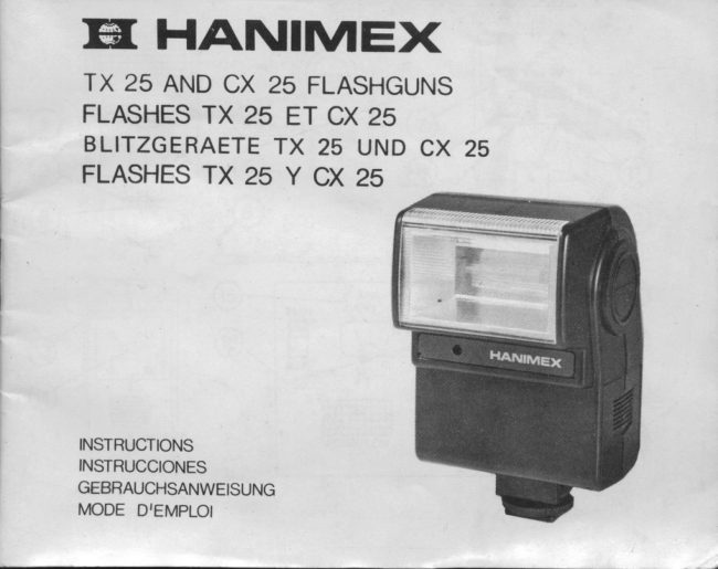
Eil HANIMEX
TX 25 AND CX 25 FLASHGUNS
FLASHES TX 25 ET CX 25
BLITZGERAETE TX 25 UND CX 25
FLASHES TX 25 Y CX 25


INSTRUCTIONS
INSTRUCCIONES
GEBRAUCHSANWEISUNG
MODE DIEMPLOI
View original page 1
Page 3 · Read text
HANIMEX TX AND CX 25 FLASHGUNS
 The Hanimex cX and rX 25 are powerful, compact, fixed head, computer fla*r-
 guns for on-canera mounting, synchronised by hot-shoe or by pc cord, and have
 the special features of battery saning Auto off circuitry, Auto test indicator, and
 externally loadable battery case. All the controls are con\reniently located together
on the back of the unit. TX 25 has energy saving thyristor circuitry.

SPECIFICATIONS
 Guide No.                         : 8O feet, ASA 1OO;25 metres, DIN 21.
 Auto operation at 100 ASA : 3 to 20 feet,1 to 6.2 metres at f4
 coverage angle               : 6o" Horizontal, 45" vertical approx. to suat 3smm
                                     lens.
                                           1/100O second. Flash duration                   : Manual - approx.
                           Auto - down to about 1/50,O0O second.Recycle time, manual          : 7 seconds with fresh alkaline cells.
Battery life                      : 18O flashes approx. on manual setting (alkaline
                                        cells)
Auto Off circuit                : Power switches off automatically when the storage
                            capacitor is fully charged. Battery pornrer is re-
                            applied when gun is fired or if On button is
                                pressed.
Autd test                         : Yellovv flash whenever computer operates.
Ready lamp                     : Flashing orange light under test button,
Power On lamp                    : Steady green light under pov\rer on button.
Connection means             : By hotshoe contact with clamp ring or pc cord.
Batteries                           : 4 x AA size Penlight cells, Alkaline preferred.
View original page 3Page 4 · Read text
LOADING BATTERIES
Slide the battery cover (4) downwards  (in the direction of the moulded-in arrowl
and lift it off to exposs tho battory casa (141. Tip out the battory case and load it
with 4 Penlight (AA Size) calls arranged according to ths marking on the case'
For fast recycling, long life and optimum pou,€r, alkaline batteries ara recom'
mended.
Insert the loaded battery cass (t€rminal end first and terminals to the right) into
the batbry chsnber (13). An illurtrative diagrrn is marked inride ths battery
chamber for your convenience. No harm arises if the battery caso is loaded
incorrectly; houpver, po,ver will not be applied to the flash gun.
ATTACHING TO CATTIERA
Screw the clamp ring (2) upurards to make room for tha fladr gun foot (31 to slip
into the accossory shoe of your camera. The clamp ring may then be screwed
downwrds to hold it fast.
lf your camera has a "hot sho€" (X sync contact in the osntre of the *roe! yot
are now ready to poirer up the flash gUn. Otherwise, insort tho PC cord irk  (6)
into the PC cord rocket (5) on the flartr gun foot and insert the plug (121 at the
other end of the PC cord into the X sync socket on your ctnsra.

PIOWERING UP
Press the "Po$rer On" button (8) and note that the green lenp (behind the
buttonl lights to indicate that the batterier are supplying  pol,vsr.
After a *rort interval (5 to 20 seconds depending on the kind and fredrness of the
batteries), the orange "Rsady" lanp will commenoe to flash behind the "Ready
Test" button (11). Your flaeh is novn ready to be fired.
                        www.butkus.us
View original page 4Page 5 · Read text
To check the unit without exposing the film in your crnere, you may prass the "Ready Test" button (1ll to fire the flash tube.
 Your flash gun employs a battery saving autornatic on-off circuit. when the
 storagp capacitor has attained the rnaxirnum chargB that the state of the batteries
 will allow, the batteries are electronically  switcfied off to avoid draining them
  unnecessarily. The green pourer lamp ir then extinguicred. The ready larip will
 ontinue to flash to indicate thst there is enough charge to fire the flash.
 ,f the flash gun is fired, the batteries and green f"-p      automatically re_
 connected to restoro the charge. lf the flash gun is not fired,"r"then wentpally the
 ready lanp will ceara to flash and you may ready the unit agpin by prusing
 thg "Poupr On" button (8).
 NOTE: There is no ,,off, lvvitch, but you may safely put a^ray your fla*r gun
 after use' knowing that it will a.rtomatically turn off to sarrs your batteries and
 knoruing also that the charge left in the capeitor will help keep it in good condi-
 tion. Naturally, if yot, do not int€nd using your flash gun for sorne weeks, it is
 better to removo the battsrior to arroid probrems of corrosion.
AUTOMATIC CONTROL
 In this mode, the light reflected back from the subioct is collected by a silicon
photocell so that the flastr is stopped when enough tight for corrsct exposure has
been computed. (ln the TX 25 the series thyr,rtor switching enrures that the
unused charge is retained for the next shot so maximising battery life).
For close-up work, tho automatic switching cr€ates a r"iy short exposure time aslorry a 1/50,0@ second wtrich can ',freeze,, ths fastest action. These short tim€s
in clos+up also mean that you can take many shots in quick succession, forexample with a motor drive.
View original page 5
Page 6 · Read text
To set to automatic @ntrol, slide the "Auto-Man" swiEh (7) downwards to the
"Auto" position and set your camera to the appropriate f-stop. lf you are using
ASA.10O (DlN 21) this is t4. For other film speeds use the slide rule calculator
 (10) by mwing the slide (18) by its knob (16) to setthe index mark (17) tothe
desired film speed on the scale (151. The aperture to set on yqrr camera is shown
on the slide (18) opposite the red dot (19). The diagram illustrates a setting for
400 ASA (27 DIN) where the appropriate aperture is f/8. For any film speed the
range of Auto operation is limited to 3 to 20 feet (1 to 6.2 metres).
AUTO TEST
When in doubt whether the shot to be taken is within the computable rangp
(i.e. very dark subject, long distance, etc.) you mE/ make a test shot with the
"Ready Test" button (11) while observing the "Auto Test" indicator (9). The
indicator will emit a short flash of light if, indeed, the shot is computable.
MANUAL CONTROL
With the "Auto-Man" switch in its upwards (manual) position, the computer
circuit is disabled and the full power of the flash is released on each shot. You will
want to use manual control when shooting at long distances, for fill-in flash, or
if your camera has "flashmatic" operation.
The guide number of your flash gun is as follows:-
              Film Speed                         Guide Number
     ASA     DIN                      Feet        Metres
       25     ,./  15                    40          12
       50        18              55         17
         6/.19                  60         19

                        www.butkus.us
View original page 6Page 7 · Read text
80        20              70         21
      100        21              80        25      160       23             100       30      400       27             160       50
For "Flashmatic" cameras you must set the guide number that suits your film
onto the flash 'setting ring. For other cameras, divide the appropriate guide
number by the distance of the zubject from the flash gun and set your camera's
aperture to the nearest, lornest stop matching this result. Alternatively, use the
sliderule calculator (10) on the brck of your flash gnrn by firstsettingthe  index
mark (17) to the film speed on scale (15) by movingthe slide (1g). Once set, you
may red off the correct f/No. on the slide (18) against the flash-to-subject  dis-
tance on scale (20). The diagram illustrates a setting for 400 AsA (27 DIN)
where if the flash-to-subiect distance is 10 feet (3 metres) the required stop is
tl16,or  af the distance is 30 feet (19 metres) the required stop is f/5.6.
For the best results with fill-in flastr application, a testshotand measurementby
an integrating exposure meter is essential. without such a meter, a good guide is
to set your camera two f-stops lower than indicated by the calculator.

BATTERY STATE
As the batteries become exhausted you will notice that  it takes longpr to re-light
the Ready lamp. Also you will notice that the lamp flastres more slowly. lf the
lamp flashes less than about once a second when the green lamp just extinguishes,
then the batteries are about due for replacement.
View original page 7Page 8 · Read text
FLASHES ELECTRONIOUES HANIMEX TX ET CX 25
Les flashes Hanimex CX et TX 25 sont des flashes i computer puissants, com-
pacts, i  tete fixe s'adaptant sur votre appareil. lls peuvent 6tre synchronis6s
soit au moyen du contact sabot, soit par cible de synchronisation.  lls possd-
dent en outre un systdme sp6cial Auto-Off permettant d'6conomiser les piles, un
indicateur t6moin et un boitier-piles amovible. Tous les contr6les de fonction
sont situ6s au dos du flash. Le TX 25 possdde en outre un circuit i thyristor pour
ticonom iser l'6nergie.
CARACTERISTIOUES:
Nombre guide                 : 25 a 1O0 ASA
Champ couvert en automatique  i 1O0 ASA (3 a 20 pieds) de 1 d 6.2m d F4
Angle de couverture       : Horizontal 60" -  vertical 45" environ pour objectif                        35 mm.
Dur6e de l'6clair                   : environ 1/10OOe de seconde en manuel iusqu'd
                             environ 1/5000Oe de seconde en automatique
Fr6quence des 6clairs          : 7 secondes environ en manuel avec des piles alca-
                                      lines en bon 6tat.
Dur6e de vies des piles          : environ 180 6clairs en manuel (piles alcalines)
Circuit Auto-Off               : ll d6connecte automatiquement  les piles lorsque
                              l'accumulateur est charg6. Le contact pile se re-
                       met en route apres avoir d6clench6 le flash ou en
                          appuyant sur le bouton "oN".
Contr6le de l'automatisme : une lampe jaune cl ignote lorsque le computer est
                          en fonction.
Lampe t6moin                : lampe orange clignotante sous le bouton de test
Lampe de fonctionnement : lumidre verte situ6e sous le bouton de mise en
                            marche.
                                                                                                                                       f ixation ou par leMoyens de connexion          : par contact sabot avec bague de
                          cordon de synchronisation.
Prtes                                 : 4 piles b6ton {AA) de pr6f6rence alcalines.
                           www.butkus.us
View original page 8Page 9 · Read text
CHARGEMENT DES PILES
Faire glisser le couvercle de protection des piles (4) vers le bas (en suivant la
direction de la fldche) et le soulever pour faire apparaitre le compartiment des
piles (14). Extraire le compartiment des piles et le charger avec 4 piles bdton
(AA) suivant les indications. Pour obtenir une plus grande fr6quence des 6clairs,
une puissance optimum sur une plus longue p6riode, nous recommandons  l'utili-
sation de piles alcalines.
Introduire le boitier piles charg6 {extr6mit6 d'abord et vers la droite) dans le
compartiment (Bl. Un diagramme est imprim6 d l'int6rieur du compartiment piles
pour vous aider. ll n'y a aucun danger si le boitier n'est pas plac6 correctement,
cependant le flash ne sera pas aliment6.
FIXATION SUR L'APPAREIL
Remonter la bague de fixation l2l atin de pouvoir introduire la base du flash (3)
dans la prise sabot de votre appareil. La bague de fixation peut Ctre ensuite
redescendue pour le tenir solidement.
Si votre appareil a une prise sabot (synchronisation au centre de la prise sabot)
vous €tes pr6t i mettre le flash en marche. Sinon, introduire  le cordon de synchro-
nisation (6) dans la prise (5) A la base du flash et brancher l'autre extr6mit6 du
cordon dans la prise X de votre appareil.
ALIMENTATION
Appuyer sur le bouton de mise en route (8) et contrOler que la lampe verte
derridre le bouton) s'allume pour indiquer que les piles fournissent !'alimentation.
Aprds un court intervalle (5 e 20 secondes suivant l'6tatdes piles) la lampe t6moin
orange commencera d clignoter derridre le bouton de contr6le (ll)votre flash est
maintenant prdt d d6clencher.
Pour vdrifier le flash sans exposer le film qui est dans l'appareil, vous pouvez
appuyer sur le bouton de contr6le (11) pour d6clencher le flash.
View original page 9Page 10 · Read text
Votre flash est 6quip6 d'un circuit de mise en route-arret automatique pour
 6conomiser les piles. Ouand le condensateur a atteint la char-ge maximum'que
 l'6tat des piles lui permet d'atteindre, les piles sont 6tectroniquement arr€t6es,
 pour 6viter de les d6chargei inutilement. La Lampd verte alors s'6teint, la lampe
 t6moin continue a clignoter pour inoique, q,re ia cnirge est suffisante pour d6clencher le flash.
 ALIMENTATION
 Lorsque le flash a 6t6 utili#, les plles et la lampe verte sont automatiquement reconnect6es pour la recharp. Si le flash n,est pa utilis6, la lampe verte s,6teindra
 peut-dtre au bout d'un certain temps, et vous pourrez reconnecter  le circuit en
 pressant sur le bouton "Power on" (8).
 NorE:  ll n'y a pas d'interrupteur "ARRET", mais vous pouvez ranger votre flash
en toute s6curit6 aprds l'anoir utili# en sachant qu'il s'arr€tera automatiquement
 et que la charge restante de l'accumulateur le maintiendra en bon 6tat.
 Naturellement  si vous n'ltez pas l'intention d'utiliservotre flash pendant quelques
semaines il vaut mieux retirer les piles pour 6viter des probldmes de corrosion.
CONTROLE AUTOMATIOUE
Par utilisation de ce principe, la lumi0re r6fl6chie par le sujet est analys6e par une
cellule photo 6lectrique au siliconequipermetau ilash de n'utiliser que la iumidre
n6cesaire calcul6e pour une exposition correcte (dani le mooele ix   ii,   t-"positlon thyristor permet de conservsr p(rur la prochaine prise de vub la charge
non utilis6e en augmentant ainsi la dur6e de vie des piles).
Pour des prises de vues rapproch6es, la position aJtomatique permet d,obtenir
un temps d'exposition anssi court que l/sooooe de seconde, ce qui permet de
saisir l'action la plus rapide. La rapidit6 de ces temps d,exposition iori de prises
de vue rapproch6es permet en outre de prendre piusieurs'photos en succession
rapide, en utilisant par exemple un moteur. Pour mettre votre flash en position  10
                           www.butkus.us
View original page 10Page 11 · Read text
automatique, faire glisser le bouton "Auto-man', (71 vers le bas sur la position
    "Auto" et rdgler votre appareil sur l'ouverture appropri6e. si vous utiiisez un     film 100 ASA (21 DIN), celle-ci sera de F 4.
    Pour d'autres sensibilit6s de film, utiliser la rdgle i calcul (lO) en faisant pivoter
     le cadran (18) par son bouton (16) pour mettre l,index (17) sur la sensibilit6
   de film d6sir6e sur l'6chelle (15). L'ouverture sur laquelle doit 6tre r.6916 votre
     appareilest indiqude sur le cadran (18) en face du point rougp (19).
    Le dessin illustre le rdglage avec un film de 4OO ASA (27 DIN) pour lequel l'ouver-
     ture appropri6e est F.8.
    Ouelle que soit la sensibilit6 du film utilis6 en automatique, la distance est limit6e   deli6.2m(3a20Feet).

   CONTROLE D'AUTOMATISME
    En cas de doute pour savoir si la prise de vue est dans les limites de calcuf (c,est-
    *dire, sujet trds sombre, grande distance etc . . . ) vous pouvez faire un test avec     le bouton de test (ll) en observant l'indicateur de contr6le d'automatisme (g).
     L'indicateur emettra un petit 6clair de lumidre si en effet la prise de vue est dans
      les limites de calcul.

   CONTROLE MANUEL
    Avec l'interrupteur "Auto-Man" en haut (manuel) le computer est hors circuit et
    toute la puissance du flash est liLt'r6e  i chaque prise de vue. Vous utiliserez le
    contrOle manuel pour photographier des sujets 6loign6s, pour un flash d,appoint,   ou si votre appareil a un fonctionnement ,,flashmatiC,,.
    Le nombre guide de votre flash est le suivant:
                         Sensibilit6 de film               Nombre guide       ASA     DIN                         Pieds        Metres11       2s        t5                    40          12
View original page 11Page 12 · Read text
50          18                      55          17
           64         r9                    60         19
           80        20                      70          21
             1(x)          21                     80         25
          160        23                     100        30
            4(x)         27                     160         50
 Pour les appareils "flashmatic" vous devez rdgler le nombre guide qui convient ivotre film sur la bague de rdglagp du flash. Pour les autres appareils, diyiser le
nombre guide appropri6 par la distance du sujet au flash et rdgler votre appareil
sur l'ouverture la plus proche et la plus basse de ce r6sultat. Autrement utiliser la
rlgle i calcul (1O) au dos du flash en positionnant d'abord le repdre (17) sur la
graduation de sensibilit6 de film (15) en d6placant le guide (18).
Une fois rdgl6, vous Fiouvez lire le diaphraqtme/nombre guide sur le guide face i
la distance du flash au suiet sur l'6chelle (2O1. Le diagramme illustre un r0glagr
pour 400 ASA (27 DIN) ou si la distance du flash au sujet est de 3 mdtres {lO
piedsl l'ouverture requise est F/16 ou si la distance esi 19 mitres (30 piedl
l'ouverture correcte est F/5,6.
Pour de meilleurs r6sultats, avec l'utilisation d'un flash, un 6clair test et la mesure
avec une ceflule incorpor6e est essentielle. Sans une telle tnesure, un bon repdre
est de rdgler votre appareil i 2 diaphragmes de moins qutindiqud pei le
calculateur.

ETAT DES P]LES
Vous remarquerez que la lampe t6moin prend plus de temps  i se rallumer quand
les piles s'affaiblissent. Vous remarquerez aussi que la lampe clignote pluslente-
m9nt. si la lampe clignote moins d'une fois par seconde quand la lampe verte
s'6teint c'est que les piles doivent 0tre remplac6es.                           12
                           www.butkus.us
View original page 12Page 13 · Read text
HANIMEX BLITZGERAETE TX25 UND CX25
      Die HANIMEX Blitzgeraete Tx2s und cX25 sind computer-gesteuert und mit.      Mittenkontakt und Kabelanschluss ausgestattet. Die Blitigeraete sind zusaetz-      lich mit einer automatischen Batter-ieabschaltung  ,o*f,  mit einem Auto      Testknopf              und mit Batteriefach,                                    das                                           die Batterien                                                    iutnimmt,      gesamte Kontrollzentrum                                                                            ausgestattet.j";  -G;;;";;Das                               befindet                                    sich                                     auf der                                                     nuectseite
      Das Geraet TX25 ist mit einenn Thyristor ausgestattet, der Batteriestrom rp"it.--'

    TECHNISCHE DATEN
       Leitzahl                          : 25 bei DIN 21
      Autoblitz bei DIN 21          : 1-62m Blende F.4       Blitzwinkel                                6Oo                                      waagerecht                                           :                                               45o senkrecht                                                     -       Blitzzuendzeit                                 Manuell                                          1/1.00O                                             :                                                      Sec.
                                            bis                                             1/50.000                              Auto                                                        Sec.
                                    7 Sec.                                                 beiI     Auf ladezeit                     :                                            guten Atkali-Batterien.
       Batterieleistu ng                 : ca. 180 Blitze bei Alkali-Batterien.
      Automatische Abschaltung   : Der Batteriestrom wird automatisch abgeschaltet,
                                 sobald der Kondensator aufgeladen ist. bie Rutta_
                             dung erfolgt von neuem, sobald der Blitz abgege_
                           ben wurde oder der spezielle Einstellknopt einJut
                                   gedrueckt wird.
      Autotest                          : Qe]be Markierung, sobald der Computer arbeitet.     Kontrollampe                   : Bei Blitzbereitschaft  erscheint ein orangefarbenes
                                    Licht im READY-TEST Fenster.
      Ladekontrolla mpe             : Der Aufladevorgang wird im Fenster POWER_ON
                                durch gruenes Licht angezeigt.
     Synchronverbindung            : Durch Mittenkontakt oder Kabelanschluss.
      Batterien                           : 4 AA Penlight Alkali-Batterien sind empfehlens_
                                u,ert.                                          13
View original page 13Page 14 · Read text
EINSETZEN DER BATTERIEN
    Der Batteriefachdeckel (4) wird nach unten gedrueckt und der Batteriekasten
     (14) entnommen. Die 4 Penlight Batterien werden, wie im Batteriekasten
     eingezeichnet,  eingelegt. Es ist empfehlenswert, Alkali-Batterien zu verwenden,
     die eine gute Leistung und eine langp Lebenszeit haben.
    Der mit Batterien gefuellte Batteriekasten (14) wird in das Batteriefach (131
     eingesetzt. Das Einsetzen des Batteriekastens  erfolgrt, wie im Batteriefach einge
     zeichnet.
     lst der Batteriekasten nlcht richtig eingesetzt, so entsteht kein Schaden, da der
     Batteriestrom  u nterbrochen  ist.
   AUFSETZEN AUF DIE KAMERA
   Der Verriegelungsring (2) wird in Richtung des Aufsteckschuhs (3) gedreht.
    Hierdurch wird eine Sicherung des Blitzgpraetes erreicht.
     lst lhre Kamera mit einem Mittenkontakt (Synchronkontakt  in der Matte des
    Aufsteckschuhs) ausgestattet, kann die Aufladung des Blitzgeraetes sofort
    erfolgen. Anderenfalls ist das Synchronkabel mit dem Stecker (6) in den Sockel
     (S) aes Blitzgeraetes einzustecken. Der am anderen Ende befindliche Synchron-
    stecker (12) wird in den Synchronkontakt der Kamera eingesetzt.

   AUFLADEN DES BLITZGERAETES
   Der Einschaltknopf POWER-ON (8) ist zu druecken. Ein gruenes Kontrollicht
     (hinter dem Einschaltknopf! leuchtet auf und zeigt den Ladevorgang an. Nach
    einer kurzen Zeit (ab ca 5 Sec. oder laengpr, je nach Zustand der Batterien),
    leuchtet die orangefarbene READY-LAMP auf. Die Beleuchtung befindet sich
    hinter dem READY-TEST Blitzbereitschaftsknopf (111. Hierdurch wird die
     Blitzbereitschaft angezeigt. Eine Pruefung des Blitzgeraetes, ohne dass der Film
14 trensportiert wird, kann durch den READY-TEST-Knopf  (1 1) erfolgen.
                              www.butkus.us
View original page 14Page 16 · Read text
Auf der Scheibe (18), gegenueber der roten Markierung (19), befindet sich die
     einzustellende Blende. ln der Abbildung ist als Beispiel die Markierung der Film-
     empfindlichkeit auf DIN 27 (400 ASA) gestellt worden. Hierausergibt sich, dem
    roten Markierungspunkt gegenuebergestellt, die Blende F.8. Fuer die verschie-
   denen Filmempfindlichkeiten  ist bei Automatikeinstellung die Entfernung
     begrenzt, z.B. bei 1-6.2m (3-20" feet).

   AUTO TEST
     Sollte Unsicherheit darueber bestehen, dass die Lichtmenge fuer eine bestimmte
    Aufnahme unzureichend  ist (sehr dunkle Motive oder groesserer Abstand), so ist
     es moeglich, mit dem READY-TEST Knopf (11)einen Testblitz zu machen.
    lm Autotestknopf (9) erscheint ein kurzer Blitz, sofern die computergesteuerte
    Lichtmenge fuer diese Aufnahme ausreichend ist.

   MANUELLE KONTROLLE
    Der Schalter AUTO-MAN (7) ist in Manuellstellung zu bringen. Die Computer-
    steuerung ist nunmehr ausgeschaltet und die volle Lichtleistung steht fuer jeden
     Blitz zur Verfuegung. Diese Einstellung wird dann gewaehlt, wenn eine indivi-
    duelle Einstellung fuer zum Beispiel groessere Entfernungen erforderlich  ist.
     Gleichfalls kann diese Art der Einstellung als Blitz zur Aufhellung (wie auch bei
    Kameras mit'Automatikbl itzeinstellung'), gewdehlt werden.
    Die Leitzahl des Blitzgeraetes ist wie folgt:
             FILMEMPFINDLICHKEIT            LEITZAHL
           ASA        DIN                 FEET       METER
         25        15                    40          12         50        18                      55          17         64         19                      60          1916       go        20                       70          21
                              www.butkus.us
View original page 16Page 18 · Read text
BESCHREIBUNG DER TEILE
    1. SENSOR
    2. BLITZGERAETEVERRIEGELUNG
    3. MITTENKONTAKT
    4. BATTERIEFACHDECKEL
    5. SYNCHRONKABELANSCHLUSS
    6. SYNCHRONKAEEL
    7. COMPUTERSCHALTER MANUELL/AUTO
    8. BATTERIEE INSCHALTKNOPF
    9. TESTBLITZKNOPF
    10. TABELLE
      1 1. BLITZBEREITSCHAFT
    12. SYNCH RONSTECKE RANSCHLUSS
    13. BATTERIEFACH
    14. BATTERIEKASTEN
    15. DIN/ASA.SKALA
    16. SCHIEBER
    17. BLENDENSKALA
    18. BLENDENSCHIEBER
    19. ROTER MARKIERUNGSKNOPF
    20. METER/FEET-SKALA


18
                              www.butkus.us
View original page 18Page 21 · Read text
COMO COLOCAR LAS PILAS
 Deslice la tapa del compartimiento de las pilas (4) hacia abajo (en direcci6n de la flecha)            lev5ntela      y                     hasta ver                                    el comparimiento                                        de                                                            Saqr"f"                                                                  oque                                                            las pilas ii+).                                                                v    pifas         penlight                 (tamafio 4                                                           para                                                                                               "of                   AA)                         de acuerdo a las                                                    indicaciones.                                                      una ,n^ri"-ia- pida, larga duraci6n y 6ptima energia, se recomienOan tas pitas alcalinas.  t,iserie
 el compartimiento ya cargado (la parte de los terminales primero y 6stos a la
 derecha) en la c5mara para las pilas (13). Para su convenien"i", rr"y rni itrrt."ion
en el interior. No se causa ningun dafio si el compartimienio de las pilasse coloca
 incorrectamente,  sin embargo, el flash no funcionar6.

COMO COLOCAR EL FLASH A LA CAMARA
 Atornilleel anillo de suleci6n (2) hacia arriba para dejar lugar al pie del flash (3)
de manera que se pueda deslizar en la zapata de la c5mara.-El anillo Oe sujecibl se atornillar6 hacia abajo para asegurarlo fuertemente.
 Si su c5mara tiene una zapata de contacto directo (contacto X de sincronizaci6n
en el centro de la zapata) ya podr5 usar su flash. De io contrario, conecte la clavija
del cord6n de sincronizaci6n (6) en la toma de corriente para el mismo (5) alpiadel flash e inserte,el enchufe (12) del otroextremodel cordonal contactodesincronizaci6n de su c6mara.

COMO€NCENDER EL FLASH
Presione el bot6n "power on" (g) y vea que la luz verde (detr5s del bot6n) se
encienda indicando que las pilas estdn abasteciendo energis,
Despu6s.de.               pequefio         un                          intervalo                                 (de s                              a zLr                                         seguno;itependiendo                                                                       del tipo-p"rlyestado                pilas)     de les                      la lu.z                              que                          anaranjada                                            indicJ                                         que et flash estd ,,riri",;
usarse que se encuentra detr5s del bot6n ,,Ready Tes1,, (,,prueba,,) (11) se
der6 intermitentemente. En ese momento poai5 ur"iV" zu tiastr.            "nt"n_
Para probar el aparato sin tomar una fotograrfa, preiione eiuot6n,,Ready Test,, 20
View original page 21
Page 22 · Read text
(11) para disparar el flash. Su flash tiene un circuito de conexi6n y desconexi6n
    autom5tica que permite ahorrar la energfa de las pilas. Cuando el acumulador de
    energia se ha cargado al m5ximo, de *uerdo al estado de las pilas, 6stas se desco'
    nectir5n electr6nicamente para evitar que se gasten innecesariamente. La luz
    virOJ se apagar6. La luz que indica que el flash est6 "list6" para usarse continuar6
    encendidndoie intermitentemente para indicar que hay carga suficiente para,usar
     el flash.
   Cuando se use el flash, las pilas y la luz verde se conectar6n de nuevo artom5ti'
    camente, para renovar la energfa. Si no se utilizael  flaslr, eventualmente la luz de
     "listo" dejar6 de encenderse y podr6 activar el aparato nuaramente presionando
     el bot6n "Power On" (8).
   NOTA: No hay un interruptor de @agndo, pero puede guardarsu flash con toda
     segr.rridad despuds de usarlo, sabiendo que se desconectar6 autom5ticamente  para
     ah-orrar la energfa de las pilas y sabiendo tambi6n que la carga en el acumulador
    de energfa ayudar5 a mantenerlo en buen estado. Naturalmente,  si no va a usar el
          f lash por varias semanas, es melor sacar las pilas para evitar problemas de corrosaon.

   CONTROL AUTOMATICO
   En este modelo, la luz reflejada en el sujeto es concentrada, Por una c6lula foto'
     el6ctrica de silicio de manera que el flash s6lo emite lui suficiente para una
    exposici6n correcta. (En la serie TX25 el sistema Tiristor asegura la acumulaci6n
    de energfa que no se ha usado, mantenidndola para la toma siguiente y prolongan-
    do asi la duraci6n de las pilas).
    Para tomas de primeros planos, la operaci6n autom6tica produe un tiempo de
    exposici6n muy corto, hasta de 1/50,000 de seltlndo, lo cual permite "dete_ner"
    la acci6n m5s r5pida. Esta velocidad en tomas de primeros planos tambi6n le
    permite tomar muchas fotograf fas en r5pida sucesi6n, por eiemplo con c6maras
21  a motor.
                             www.butkus.us
View original page 22Page 23 · Read text
Para hacer funcionar el flash con el control attom6tico, deslice el interruptor
 "Auto-Man" (7) hacia abajo hcta la posici6n ,,Auto,, y regule su c6mara en el
 punto "f" adecuado. si utiliza ASA 100 (DlN 2l) deber5 colocar f4. para otras
 sensibilidades de pelicula, utilice el calculador (10) moviendo la gufa figl con la perilla (16) hasta col@ar la sefial (17) en la sensibilidad de petiiuta qlJi"re"
de acuerdo a la escala (15). La abertura qr.re deber6 colocar, se seftala en ta gJfa
 (18) con el punto rojo (19). La ilustraci6n tiene como ejempio el uso Oe COO ASe (DlN       .27), en. cuyo cpso la abertu:a apropiada es f/g. para'cualquier sensibilidad
de pelicula el alcance de la operaci6n autom6tica est6 limitado Oe S a ZO pies {I a 6.2 metros).
Cuando est6 en duda si el sujeto a ser fotografiado est6 dentro del limite o no(por ei. un sujeto muy oscuro, distancia targa, etc.l podr5 hacer una prueba con
1.9o!9n -"Ready Test" (ll)  mientras obsirva el indicador,,Autd'f"ii;   igi.El indicador emitir5 un pequefio halo de luz si la toma est6 dentro oef aican#.


CONTROL MANUAL
cuando el interruptor "Auto-Man" est6 hacia arriba (en manual) elcircuito com-
puterizado no funciona y toda la energia del flash se despide en cada toma. Seutiliza                        para          control               manual       el                          tomas                          a larga distancia, para flastr o"(relleno)        o              si la c5mara                         tiene                            operaci6n                                                                  "povo                                                                                ,'f lashmitic,,.
El n0mero gufa de su flash es como sigue:-
        SensibilidadASA  de la DINPelicula            PiesNtmero GufaMetros       25         15              40         12       50         18              55         17
                                                                                              21       64         19              60     19
View original page 23Page 24 · Read text
80         20                      70          21
              100           21                      80         25
              160         23                      100         30
             400         27                     160         50
   En las c5maras "flashmatic" deber5 colocar el n0mero gufa apropiado para su
     pelicula en el anillo de ajuste del flash. Para otras c5nraras, divida el n0mero guia
    adecuado entre la distancia que hay del sujeto al flash y regule su c6mara usando
      la abertura m5s cercana ala m5s baja de acuerdo al resultado que obtenga. Alter-
     nadamente, utilice el calculador-de  regla deslizante (10) que est6 en la parte pos-
      terior del flash y coloque !a sefial (17) en la sensibilidad de pelicula en laescala
      (15) moviendo  la guia (18).
    Una vez regulado, lea el No./f correcto en la guia (18) de acuerdo a la distancia
     del flash al sujeto en la escala (20). La ilustraci6n tiene como ejemplo el uso de
    400 ASA e7 DIN) en cuyo caso, si la distancia del flash al sujeto es 10 pies
     (3 metros) se deber5 usar f/16, o si la distancia es 30 pies (19 metros) se usar5
      f/s.6.
     Para 6ptimos resultados utilizado flash de apoyo (relleno), es esencial hacer una
    prueba y utilizar un medidor integrado de exposici6n. Sin ese medidor, puede
     calcular utilizando dos puntos f/m5s baios de lo que indica el calculador.

   CONDICION DE LAS PILAS
    Cuando las pilas se gasten, podr5 notar que la luz de "listo" se demora en encen-
     der. Asimismo, notar6 que la luz se enciende y se apaga m5s lentamente y si lo
    hace menos de aproximadamente una vez por segundo, cuando la luz verde se
23  apaga, entonces se deber5n cambiar las pilas.
                              www.butkus.us
View original page 24From the M. Butkus archive. Original publisher and archive notices are retained.
Check the model and edition against your equipment.
PDF verified 2026-10-10.