Film cameras
Heiland Model S Synch User manual
User manual for Heiland Model S Synch. 11 pages in English. Read the original PDF, download or print a copy without registration.
11 pagesEnglish4.1 MB PDF
Loading your manual…Open PDF directly
Document details
- Brand
- Heiland
- Model / document
- Heiland Model S Synch
- Document type
- User manual
- Language
- English
- Pages
- 11
- File size
- 4.1 MB
- Category
- Film cameras
- Document date
- Not specified in catalog
Search available document text
Find a term, then jump to its page in the original PDF. Image-only pages may not be searchable; check the PDF for exact wording and diagrams.
Page 1 · Read text
www.butkus.us
   INSTR,UCTIONS FOR, MOUNTING HEILAND MODEL S SYNCHR.ONTZER
   J:olI'( Lcrt4ND SYNCHRoNIZER IS A CAREFULLY DESIGNED AND ENGINEEBJD pIECE oF pHoTocRApHrC   FgV-IP-ME. I!             CAREFIjL INSTALLATION ACCORDING TO TI{E FOLLOVING OINTCNOT.TS \ruL ASSURE YOU MANY YEARS OF SATISFACTORY SERVICE. TTTERE I' NO FINER SYNCHiONiZiT r-,ri-IJr.
        HEITAND PESIAPCH COPPOPATION
                                     I30 EAST FIFTH AVENUE
                                      DENVER, 9, COLORADO


       R-EQUfRED: One No. l0 Drill, Small Hand Drill, one 2xfl Tap, Screw Driver, ^TOQLS Small Pair Pliers, Small File.
 SHUTTERS And CAMERAS FITTED VITH THE MODEL .IS'' SYNCHRoNIZFRS:
 3t/ax4r/4,4xs and Jx7 GRAPHICS, B and J, Linhoffs, gxl2 Recomar,2/ax3/aGraphic,  erc.

                            SUPERMATIC                                                                    www.butkus.us
 The HEILAND Synch-ronizer coils can be- easily fitted to Supermatic shutters if the following
 directions are followed closely. The synchroniLr,    be used at all shutter speeds from I sec. to l/400th sec. and on the later model shutters the"rncoil can be used to open the shutter on
 time and bulb.                                                                                                                                                                                                                      Digitally signed by Mike Butkus
                                                                                                                                                                                          DN: cn=Mike Butkus, o=Butkus
                                                                                                                                                                                         camera manuals, ou=butkus.org,                                                  Mike Butkus email=mike@butkus.org, c=US
                COMPUR, COMPOUND, ILEX, ACME                                                                                      Date: 2021.03.28 17:17:24 -04'00'
 The HEILAND Synchronizer caln be used with all the above shutters and at all speeds from I sec. up.'The inst*llation methods are the same with the exception that some of ih. Rirrgr.,
                                        a small return ,prirrg (A) Fig. I on the shutterQmprrr shutters -require the installation of
 tripping lever as shown in the diagram. Any competent ,h.rtt.i r.iri.-"n  cir install th" rf.irrg.
          ...--                   +-
 on most shutters.                                                                                                 -{
                         INSTALTATION
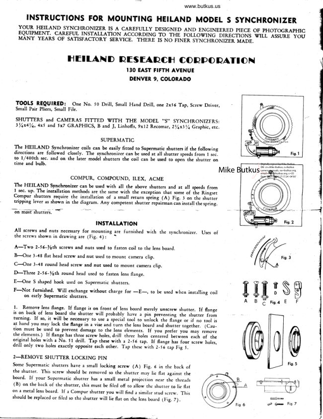
 All screws and nuts necessary for mounring are furnished with  the synchronizer. Uses of the screws shown in drawing are (Fig. a) .    \
A-Two 2-f 6'/sth screws and nuts used to fasren coil to the lens board.
B-one 3-48 flat head screw and nut used to mounr camera clip.
c-one 3-48 round head screw and nut used to mount camera clip.
D-Three 2-t 6-/srh round head used to fasren lens flange                  w,,
E--One S shaped hook used on Supermatic shutters.
F-Not furnished. Vill exchange without charge for        to [x use4 wlrc' instrling coil    on early Supermatic shurteis                  -E-,              3s$
                                                                                                          Fis.4 E                          F.F. l'  Remove lens flange..If flange is on front of lens boarcl merely unscrew slrutter. If flange
is on back of lens board the shutter will probebly have a pin ireventing the shurter fromtur-ning. If so, it. will be necessary to ur.                                                      .special tool to        the fl#ge or if ,,o tool is                                               "   handat       you         mey                 lock                      the                             frangg                               a vise                                      and                                   in                                                   rhe lens                                                        board""1".t                                       iurn                                                                        shutte?                                                          a.d                                                                              ,ogeth.r.                                                                                icru-tion               used-    must          bc                 to prevent                         damage                                      to                                       the                                              lens elements.                                                 you                                                                                           yo.r"                                                                            If                                                                                                           ,.J-orn.                                                                                   fr.f..                                                                                       -rf-the    elements.)                      flan-ge                       has                    If                              three                                              holes,                                      rc.-e*                                                three                                                         hole,                                                  drill                                                                berween                                                            ..n,"r"d                                                                    each                                                                                                rhe                                                                       oforiginal holes with a No. ll  drill. Tap these with e 2-J6 r.ap. If flange has four screw holes,
drill only two holes exactly opposite each orher. Trp rhese iith   2-f 6 tap Fig I.
2-REMOVE SHUTTER LOCKING PIN
Somc Supermatic shutters have r small locking screw (A) Fig. 5 in tfie beck of                                                       Fig.5
the shutter. This screw should be removed so the shuttcr rn:ry lic fl,rt ag.rinsr the
board' If your Supermatic shutter has a small metal projcction nclr thc thrcl4s
(B) on the back of thc shutter, this must be filed off to allow thc shuttcr to lic flrt
on a metal lens bolrd. If a Compur shutter you will find a similrrr srud scrcw. This
should be replaced or filcd so thc shutter will lie flar on thc lcns bo:rrd (Fig. z).
                                                                       e-l,pwW,   Fis.7
View original page 1Page 4 · Read text
www.butkus.us                               Poge 3
7. Screw shutter flange down tight and lock in position with three screws supplied. Make any
slight correction necessary in length of tripper arm and bail due to shutter moving while youwere locking the flange.                           \#-+L+3c
                                                                                        head8. Remove knurled cap ( lC) Fig. 8 also plunger rod and head. Replace coil in tripping                                                                                                                                            Fie.lOand set screw (tB) Fig. 8 slightly.           @\+/-
9. Loosennut (3C) Fig. l0onplungerheadand  adiu.st rod 1lB1 lcngtb until plunger iust
trips sbuttm uben plunger bead (1A) seats on tolt of coil. (This adjustment must be done very
slowly as a sudden push will trip the shutter without the head being properly seated.),*'
10. After the above adjustment is made, hold long end of plunger rod firmly and' back plunger
                                                                  plunger is adjusted_ ProP-head off one full turn and tighten lock nut (3C) on plunger rod. If
erly there *;ll be   gxp of trot over  | / 54th of an inch beto'gsn the plunger head and the coil
when the shutter is             ^ tripped. File off surplus threaci to within l/64rh inch above nut (lC).
11. Irtsert plunger into coil. Loosen screw (4A) Fig. ll  until it just clears inside of coil cap.                            www.butkus.us
Remove coif rsrimbly from head and replace cap, screwing cap down until dots on cap- and
coil line up when tight. Replace completed coil assernbly, locking screw (lB) after.coil termi-
nali are r.t    the proper angle (approximately 4t degrees) so camera will close without              "tterminals interfering
                                                                             Be sure to lock nut. NOV tZ, Tightet screw (4A) until tripping arm (2A) just moves. Then turn the screw /2 rurn down.
CHgCf rOf SYNCHRONIZATiON. l"y  further adjustments are made as followsr To slow tripper, I-ENTHEN ROD (!B); to
speed up rripper, SHORTEN RoD (lB) Fig. 10.                                                                                      ..                                     I
 * * * Reedjustment of front bord lenc stopc is necessery only when the 0rnge wer origiaelly on thc front of'the botd, and is crsily
 eccomplished by focusing with the ground gllss.


                           MOUNTING THE BAT"TERY CASE
 Fasten battery case clip (tA) to the camera with screws and nuts supplied. Loosening screw
                                                                                                            also (lB) allows the batrery case to be revolved for either right or left hand mounting and
 adjusts for vertical position. By tightening this screw the battery case clip will slide in and
-our r€ey--easf. If-y-ou a4puH-li&c ts,$ave-it fu.rnore snugly, loosen the screw undl the clip is
 tighter in the camera case clip. Note: If the clip is fastened to a rangefinder bracket, drill
 the bracket with a No. 47 drrll and tap with 1x48.
 Alrhough  all HEILAND battery cases are set for forefinger operation, thumb operation may be
 had    removing screws (tC) and revolving the reflector ring to a corresponding position on   $
 the ofposite side of the case. However, we do not recommend this as with the switch button
 ser for forefinger operarion there is less chance oI any camera movement since the synchro-
 nizer is fired somewhar like a gun; i. e., squeeze the trigger until the shutter is tripped by the
 snap acrion of the switch. Try this a few times until you get the feel of it.


           CONNECTING CORDS AND HO:IV THEY ARE USED
 The cord that cJnnects the coil to the battery case may be plugged into either one of rhe silc
 outlets (6A) on the case. Either one of rhe side outlets can be used for extension lighting
 by merely plugging in an extension lamp cord and reflector. If you wish to use more than one
 extension lamp use a double socket in the side outlets on the battery cese or wire your two
 cords together with one male plug" To make this type of setup practical, one of the extensions
 should be longer than the other. An example is to have one cord I i feet long and the other 2 i
  feet long. V'henever using extensions check your batteries to make sure they are of sufficient
 Power to take care of the extensions. New batteries should have l0 amps or more and when
  batteries fall below 7 amps they Should b€ discarded.
 CAUTTON: THE OUTLET OPPOSITE THE SVTTCH'(68) IS IO BE USED FOR RE-
 MOTE CONTROL OPERATION OR IO HAOK UP THE TVIN HEILAND T]NIT,
 AND FOR FACAL PLANE SYNCHRONIZERS. Ary pear typ€ switch used on the end of
 a cord plugged into this ourlet will act as a remote control whenever the circuit is closed.
 CAUTION: DO NOT USE OVER 20 FEET OF CORD ON REMOTE CONTROI
 UNTESS AN AUXILIARY BATTERY SUPPLY IS PRO\IIDED.
View original page 4Page 8 · Read text
www.butkus.us

                                                       l,|ou     filtrnucTtou, {0,. lvlouNTtNc                                         5wcHnoiltzER                    30[                  e$                       0" 5t *    4 x 5 or 5 x 7 Speed Graphic                                4,

                               Your nSOLr Synchronj-zer is a carefully designed. and
                                   engineered piece of photographic apparatus. CarefuL
                                    installation according to the followlng directions
                                      wiII assure you many years of satisfactory service.
                                                     Tools Reouired.
                                      One No. 50 Drill         Snall Hand Drill
                               One2x56Tap          Screw Driver
                                         Snall Pair Pl-iers
                                         Small FiIe                         www.butkus.us
      tfsOT,rt                       A1l screws and nuts necessary for mounting are          Model S Synchroni zer     furnished with the Synchronizer.        on Speed  flnqnh   i n
                                                             ooOoo

                             TO INSTAIL PROCEED A,S FOIiOWS:
                                  Mounting Coil - 3**  o.t, 4 x S, 5 x Z Speed Graphics.
                                Remove the lens and lens board from the canexa. Unscrew
                                   shutter and remove flange. DriII  and tap a No. 50 hole                                   (IA) in the lens flange for the brass p-56 screw (sup-
                                  plied) and just start the screw. push the thread.ed end
                                  of the shutter through the l_ens board and. screw on the
                                         J-ens flange at the back sld,e of the board *(See fig.  1).                                  Tighten the shutter just enough to hold it  firnrly i_n
                                 place but still  allow it  to turn.
                                          rnha *rinn'in-  coil  shoul_d be mounted. near the bottom of
                                                          ;il   ;;;;;i""oot  the entire assembr-y may be operated and
            FlG.l.                the camera closed wi-in tne coll at the top, sid.e, or
                                  botton-(except in the case of the large old type Compur
                                    in a 5| x 4l  size where only top or side mounting may
be used). Move the aperture (f.  stop) lever as far cl-ockwise as possible to make sure that
1t wiII not interfere with action of tripping arm (2D). Now turn ad.justing screw (2A)
cloclstrise as far as it  will  go, to lock plunger assembly down. ft wilL be necessary !o
loosen the lock nut on screw (2A.) to do this.  Engage the link (ge) with the shutter trip-ping lever.   ff  neeessary to engage link and lever, loosen screw (ZC) ana rotate offset'linlr om l2n'l t /2 turn.  Be sure to re-tighten screw (2C). Then, holding the coil parallel
with the side of the l-ens board, move the whol-e tripping coiL assembly as indicated by
arrow in Flgure 2 until the shutter just trips, but no farther.  Be sure'that no part of
the co11 assembly conflicts with the shutter. Now, using the base plate (ZE) as a tem-nlaro       ''a+moFL +lro positlon of slct (2F) on the lens board with a sharp instrument such as a           '                                      need.Ie or pin.  Drill  and tap the lens board. in the
                                                                                         mirld'lo         nf      *l.ra      a'ln*'laa^*ia*                       r'.i+L       +L^:-i1i                    ^-i         !--
View original page 8Page 9 · Read text
may                                    in a  f x 4l size where only top or side mounting                                                                     make sure thatbe used). Move the aperture (f.  stop) lever as far cl-oclcwise as possible to
                                                 Now turn adjusting screw (2A)1t will  not interfere wi-th action of tripping arm (Zn).
cloclauise as far as it  wiII go, to loek plunger assembly down. It  wil-I be necessary to
loosen the lock nut on screw (2A) to do this.  Engage the link (Ze) witn the shutter trip-
ninoP1116      !vrvr.towAyr- Tf neeessary to engage link and Iever, Ioosen screw (2C) and rotate offset
Iink arm (2D) t/2 turn.  Be sure to re-tighten screw (2C). Then, holding the coil parallel
                                                                                           bywith the si-de of the lens board., move the whole tripping coil- assembly as indicated                                                     Be sure-that no part ofarrow in Flgure 2 until the shutter just trips, but no farther.
thc eol'l assembly conflicts with the shutter. Nor, using the base plate (2n) as a tem-
                                                                                                    aplate, mark the position of slot (Zf) on the lens board with a sharp instrument such as                                  needle or pin.  Drill  and tap tJre lens board in the
                                 middle of the slot location with the d.rill and tap
                                furnished. Temporarily secure the tripping coil to the
                                 lens board with a 2-56 screw and nut.  The nut may be
                                 omitted if a metal lens board is used.
                                                   If   it  is necessary to lengthen or shorten arm (2D) to
                                  obtain proper synchronization, this nay be accomplish-
                              ed by loosening screw (ZC) ana then revolving entlre
2                                  shutter to brin€ shutter tripping lever into proper                                                                                                     (2C)                                  position. When completed remember to tighten both
                                         (rie. 2) and screw (rA) (see Fig. 1).                    2A
                                Remove knurled cap (2G) and back off ad'justing screw
                               www.butkus.us                                   (2A) until  it  is nearly out. Now, pressing plunger
                                head (3A) shoufd just trlp the shutter at the end of
                                                                                                        (5A)                                          its stroke. Slight adjustment of the plunger nead
                                  -ou the plunger (Sg) may be necessary. Be sure to re-
                    FtG.2.                  tighten lock nut (5C).
                                                                                                                                                                                                                                iiII
View original page 9Page 10 · Read text
www.butkus.us

       It may be necessary to sllde the coil assembly along slot  (ff') and. adjust the length of link
    arm (gO) for proper action. The position of the terminal prongs (af) may be ad,justed. by
     stlghtly loosening set screw (2I1) and revolving the entire coll untlI the prongs clear any
     obstructlon when canera ls elosed. After the permanent posltlon of the coll assembly ls
     establlshed, mark the posltion of hole (ff)  at the lens board and after drlIllng and tapping,
     secure with a 2-56 screw and nut.
     Replace cap (2C), serewing it on tightly  until the spots line up. gcrew in ad.justlng screw
     (2A) untll the sh,rtter trlps satisfactorily when the battery case is connected. and the
                                     srltch is pressed..
                                              *Readjustment of the front board stops on lens
       \5A3cjrn                                tracksonly when(tothernalntainflangeproperwas origlnallyfocuslng)onls thenecessaryfront                 '\    \   /                                             of the board., and is easil-y accompllshed by focus-
                                               ing wlth the ground glass.
                                    FrG. 3.               MOHSIING BAfTERY CASE -- Tasten battery case clip (49) to  =fl-:-+-                                    canera wlth screws and nuts provided (See I'ig. a).  Loosen-
                                    lng screw (4A) allows the batterT case to be revqlved. for
     elther right or left hand mountlng as well as ad.Justed for vertlcal positlon. When cllp
     (48) is fastened securely to c€rmera, siide clamp lnto 1t untll  it  snaps lnto plece. Adjust-
    ment of screw (+R) wlll  glve elther tlght or loose flt  as desired. Connect cable; the
     battery-case end of the cable may be ptugged into elther slde outlet.  The thlrd outlet ls
     for remote eontrol or for focal plane synchronlzer.
    Note: When the cord ls plugged in this outlet, an automatic lock prevents operatlon of the
     swltch. After the removal of the plug from this outlet, the switch will be sttff  untll  lt
    has been pressed once.
                                     Although all nSOLn Synchronizers are set for foreflnger
                                         switsir operabton, thunD operation nay be had by removing
                         www.butkus.us               reflector ancl screws (+C), revolvlng reflector ring (4D)
{                                    to a corresponding posltlon on the opposlte sid.e of the
I                                     battery case and replaclng sclews (4C).
t-
                                      SYNCI{ROMZAIION                                                                 -- Exact synchronization, whlch should be
                                   made wlth shutter at maxlmum speed, is obtained by adjust-
                                  lng screw (2A) (See Fie. 2).  gcrew in to speed up aetion,
                                    screw out to retard.. (From t/+ to L/2 turn ls usually
                                      sufficient to reach flnat adjustment). Tighten lock nut
                                 on screw (2R) ana see that the 1lnk hlnges freely on the
                                     tripping arm.
                                 YOUR C^AMERA IS NOW HEADY f'CR TJSE -- For TIME and BULB
                                     shots slnply unhook llnk for tripping Iever.
                                 3or daylight shots without Flash Bulbs use your rSOLn
                                     Synchronlzer in pfeference to a cable release.
                                    Always be sure your batterles are in good condltlon.
                                   Change them perlodlcally oT accord,lng to the amorrnt of
                                  use they have had.
View original page 10Page 11 · Read text
Keep cord contacts clean and your sbutter, coil and trlpping arrn fres from d.ust and dlrt.
    I'ACTORT tr-I:{CT{R0NIZING AND SHLITTER TEST -- Because of the exacting work that many photo-
    graphers are required to do, particularly in color, we have frequent requests for factory
    synchronizing of cameras and rfsOtrn Fl-ash guns. If you d.esire this service, we will do the
    tnounting and synchronizing and send. you oscillograph records of the fl-ash and shuttor per-    formance of your camera made with our photoelectric Eye equlpment./
                                 Have your photographic deaLer ship your camera to us with.
                                         ord.er for synchronizer. The additional charge for this
                                   service is merely to cover time in the laboratory __ $Z.SO,                                  plus maillng costs.
                                  HETIAND RESEANCH
      This ls The Type of Oscillograph Record               CONPORAlTON
               You Receive.
                                                             700 Club Buiki.ne Denver, Colorado
It
View original page 11From the M. Butkus archive. Original publisher and archive notices are retained.
Check the model and edition against your equipment.
PDF verified 2026-10-10.