Film cameras
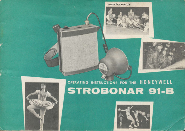
Honeywell Strobonar 91-B User manual
User manual for Honeywell Strobonar 91-B. 36 pages in English. Read the original PDF, download or print a copy without registration.
36 pagesEnglish11.5 MB PDF
Loading your manual…Open PDF directly
Document details
- Brand
- Honeywell
- Model / document
- Honeywell Strobonar 91-B
- Document type
- User manual
- Language
- English
- Pages
- 36
- File size
- 11.5 MB
- Category
- Film cameras
- Document date
- Not specified in catalog
Search available document text
Find a term, then jump to its page in the original PDF. Image-only pages may not be searchable; check the PDF for exact wording and diagrams.
Page 2 · Read text
This book has been prepared to help you take better pictures with the Strobonar
g'i-g. An understanding of the contents will help you get optimum results
from your unit and greatly add to your picture taking enjoyment.
View original page 2
Page 4 · Read text
Venmo @mike-butkus-camera  Ph. 2083
PayPal Name  Lynn@butkus.org      www.PayPal.me/lynnbutkus
View original page 4
Page 5 · Read text
WHY ELECTRONIC FLASH?                        tronic flash also gives a very penetrating light
    Eleclronic flash is a repeating source of     with amazing abilify fo record shadow detail
                                                                                               espe-photographic ligh+. A flash tube which may     without blocking up high lighis. lt is
be fired many thousands of fimes is used in      cially suitable for portraits, since it eliminates
                                                                                                                               inplace of conventional flash bulbs, and should     the need for hot, glaring lights that resulf
provide light for more picfures than the aver-      squinfing, wrinkles, and self-consciousness.  Be-
age photographer takes in a lifetime.            cause its extremely brie{ flash has no effect
                                             on the subiect's eyes, it eliminates contraction                      '::s.:r\   Aside from the convenience and porta-                                                    of the iris, resulting in the larger pupils which                'jbility afforded by electronic flash, it has many                                       add characfer to your porlraits.advantages which make i+ the ideal lighf                                     q
source for all-round professional use. lts ex-    How The Strobonor 9I-B
                                                               Eosier tolremely short  f lash duration, for example, is    Mokes lt                                           Toke Belter Pic?uresnot only useful for photographing action, but
                                                                                                                                                                                                                                                                                                                                                                                                                                                                                                                                        ifor minimizing camera and subiect motion in        Expert pholographers have long recog-
any situation to produce negatives thaf can      nized that the most important element neces-
be satisfactorily enlarged to many diameters.     sary to iake good pictures is light. Even the
                                                      finest lens cannot make a phofograph without The light delivered by electronic {lash units                                               proper lighting. This is the reason press pho-closely approximates the color  f emperature of                                                fographers and other professionals use flash,daylighf. This means you can simplify your                                               not only for indoor picfures, buf for supple- procedure,  if you wish, and use daylighr color                                             menting daylight as well.films for all your work. No filtering is required
 except for special effecfs or where extremely       The Strobonar 9l-B is compacf enough to
 critical color reproduction is necessary. Elec-      carry conveniently on any assignment. Because

 2
View original page 5Page 7 · Read text
Lompheod
  A Ready Ligh+ on the lamp head indicates
when the unif is ready to flash.
   [o insure proPer connections the shutter
cord oullet located on ihe back of the ref lector
is coded by a red dot. The Power cable which
connects the lamp head and the power pack
is permanently attached to ihe lamp head, thus
preventing poor conneciions. All componenls
in the Strobonar 9l-B are of the finest quality,
specially designed for photographic applica-
tion. The unit is precision engineered and built
io give years of trouble-free operation.
   The Strobonar 9l-B Custom Head can be
fitted to any of the standard size "D" batiery
cases or lt/2" Honeywell mounting tubes and
used with the mounting brackets described
on pages 16 and 17. tt can also be mounted
directly on the camera with a universal shoe
mount.
Strobonor 9l-B Custom Heqd Operotion
   The Hi-Lo Switch on the Cusfom Head
 will provide maximum light output with the
 switch set in ihe "Hi" position, or 25% of
View original page 7
Page 10 · Read text
www.butkus.us

        pacity to a singfe famp head connected fo ii.     Slrobonar 9l-B for over 95% of ihe flashes
        Thus, 50% of the maximum lighf available       available from a fulfy charged sei of bafieries.
       from the Sfrobonar 9l-B is utifzed by con-     The meter needfe reiurns lo the green area
It       necfing a single lamp head fo fhis receptacfe.      after each flash unlil fhere is iusi sufficienf
                                                    energy remaining for a few more flashes.          .   The lamp head should be pfugged into the
           "f 00" receptacfe for close-rp phoiography, and        The light under the Selecfor Switch witl
        for fast action shois. When operating irom ihe     go out when the fransistor controlled baftery
                                                                            1 500 second du-      cut-off circuit is operaiing. The ope.a+or           " 100" receptacle, a flash ol    l /
        ration is produced. When operating from the      should not become concerned when ihis hap-
       "200" receptacfe, a flash of  | /750 second dura_       pens.
        tion is produced. Two lamp heads may be used          In all cases, observe the Ready Light on
        simultaneously by connecting a lamp head to      the lamp head to know when the unif is ready      each of ihe recepiacles on fhe power pack.      to flash.
     When two lamps are used, the ffash duration  is     NOTE:
                      | /1500 or faster, and the lighf output of the unif                                                                 special                                    A                                                                                   circuit                                                                                       the                                                                            feature of                                                                                           Strobonar         is divided equally between the iwo famp heads.       9 f -B                                                             permits                                                               fhe                                                                 temporary                                                                             use                                                                                            standard                                                                                  of
        The mefer located on top of +he power      size "D" phoioflash dry bafteries in place of
      pack indicates the condition of the batieries.      ihe nickel-cadmium batferies. lf baftery oper_
     When fhe indicating needle remains in the      afion is necessary at a time when the nickel_      red          area                 affer                    fhe                           unit is flashed, fhe bat_     cadmium balteries are discharged, simply re-        leries             should                        recharged.                be                                                         place them with standard size ',D', photoil"rh
         -           Th." power pack charging circuit is de-     dry batferies. (Follow the instructions on page       signed to give consfant lighf oufpui from the      l0 for baftery insfallation.   )
View original page 10Page 12 · Read text
www.butkus.us

     RECHARGEABLE BATTER,Y FEATURES             teries before sforing your unii and it will be
          The rechargeable D batieries supplied with      ready to use when you need it.
        this unii are nickel-cadmium cells. The in-         Nickel-cadmium batferies do not require
        herent characteristics of +his type of battery      periodic addition of liquid electrolyte as did
      make it especially suitable for electronic flash      previous fypes of rechargeable batteries.
       requirements. They may be recharged as often     There is no danger of spilling or leaking be-
       as necessary without loss of eff iciency, and,      cause nickel-cadmium batteries are positively
      when stored in a fully charged condition, will      sealed. The Strobonar may be stored for in-
                                                        definite periods, whether the batteries are       hold their charge for ihree months. Make it
                                                     charged or discharged, without damage to the       standard procedure to {ully charge fhe bat-                                                           unit or the baiteries. The batteries and the
                                                        Sfrobonar are unaffected by temperatures up
                                                    to  I 30o F. and as low as 0o F.
                                           REPTACING CEttS
                                                      To replace cells in the Sfrobonar 9l-B power
                                                          pack, place the power pack on its back and re-
 fu,                                              move fhe two coin-slotfed screws from lhe bot-I  i':                                               iom. Remove the bottom, +ip the pack, and
                                                                   slide the cells out of their tubes. Slide the re-
                                                      placement cells into the cell tubes, observing
                                                      the polarity shown on the mefal botlom of +he
                                                                    case, for each hole.
                                                                           Replacing cells in lhe Slrobonar 9l-B Power Pack.         9
View original page 12Page 13 · Read text
CAUTION                         CHARGING BATTERIES
   Be sure to observe the correct polarity when                                   When the Sirobonar is operated with the
insfalling bafteries. Follow the instructions on the                                                          fully charged Sonotone Cells, it will deliver achassis plate adiacent to the battery tubes. The                                            minimum of 40 ftashes from the "200" recepta-top end of the nickel-cadmium baliery (the end                                                        cle. When Gould lndustrial D Cells are used,with ihe small terminal) is positive (*). The bo+-                                         a minimum of 125 flashes are delivered from ihefom end (+he {lai end) is negative (-). The +er-                                                "200" receptacle.minal end of standard photoflash dry batteries
is positive.                                  To charge the cells fhe line cord is plugged
                                                         into a 105- 129 vol+, 50-60 cycle outlet: the other   After replacing the batferies, furn the selec-
                                           end is plugged into the special receptacle in ihetor switch to the "BATT" position. lf the meler                                                  Sirobonar power pack and the swiich turned toneedle moves off scale on the red end, or does
not move well into the green area (with freshly
charged bafteries), check ihe battery installation                                   www.butkus.us
  make          certainto                that the batteries were placed   "Sq      fubesin the             properly.
   The Strobonar may be reassembled by hold-
ing'the bottom against the power pack and re-
placing the frro coin-slotfed screws.
             t?o:lirst           Sirap first slide small screw
        :?i;,.          oShoulder
     BOTTOM: Loosen coin-slotted screws in ihe boiiom of
       lhe Power Pack.


t0
View original page 13Page 14 · Read text
www.butkus.us
"CHG" position. The Sonotone Cells will take       coin-slotted screws from lhe bottom of the power
on a full charge when leff on "CHG" Ior 24     pack and remove the boffom, and fhe batteries.
hours. Gould Industrial "D'' cells take a  full       Feed the excess nylon strap into (or pull oui of) the iriangular
charge in 20 fo 28 hours. When unplugging ihe         hole.
line cord affer charging, be sure to turn the       Feed the excess strap into the triangular
                                                                                                         po\Merswitch fo "OFF" posifion or the cells will dis-     shaped hole in the bottom plafe of the
charge.                                            pack. lf fhe strap is still foo long, repeaf fhese
                                                      operations on the other side panel of fhe powerCAUTION                                                  pack. lf +he strap is to be shorfened more than  DO NOT attempt to charge regular photo-                                                  approximately 12", the excess musf be cuf off,flash dry bafferies. The baiferies will be de-                                              as the triangular cavities, on either side of thestroyed and the Strobonar may be damaged.                                            power pack, will not accommodate a greaier re-
SHOULDER STRAP ADJUSTMENT
   The shoulder strap has two convenient me{h-
ods of adiusfment. The comfortable leaiher strap
may be shortened or lengfhened by changing the
position of +he holes in ihe side buckles.
     lf the nylon strap is too long, insert a small
screwdriver under the strap near the cenfer of
the power pack side panel and work the strap
free of fhe slot. Grasp the strap and pull down
and away from the case until the loop above
the power pack is the desired lengih. Loosen fhe
View original page 14Page 15 · Read text
serve lengfh. Replace the batteries and the bot-    OPERATION-BATTERY
        tom of the Strobonar and insert lhe edges of the        Connecf the shutfer cord to fhe Strobonar
           strap into the slofs on the sides of the case.          lamp head and to the camera {lash terminals.
                   lf the strap is too short, insert a small screlv-      (Your Honeywell dealer can supply the proper                                                              shufter cord for your camera.) Plug  f he cord          driver under the sfrap near the center of the                                                 from ihe lamp head inio the desired recep-        power pack side panel and work fhe sfrap free
                                                               lacle on the power pack. (For high light out-         of the slot. Grasp the strap and pull down and
                                                   put use the "200" receptacle;  f or low light        away from the power pack until a few inches of                                                                                                                                                                                                                                f he "Hi-          slack is acquired along the side of the case.     ouipuf use the " 100" receptacle. Set                                                       Lo" Switch to +he position desired. Turn the se-         Loosen the coin-slotted screws from the bottom                                                                  lector switch to the "BATT" posifion, wait for         of the power pack and remove the bottom and                                                              the Ready Ligh+ to glow and snap the picture.   )          the batteries. Pull fhe strap end oul of the *rian-
          gular hole in the bottom plafe. At leasf l" of    NOTE
                                                              +he meter needle is in fhe red area, the         the strap must be reinserted into the triangular              lf
                                                           batfery voltage may be too low to light the          hole to anchor fhe lower end of ihe strap. Grasp
                                             neon lamp which illuminates the selector          the strap above the fop of the power pack and
                                                                  switch.           pull up at an angle away from the side of the
         case until the slack is taken out of the strap. lf    OPERATION-tINE
        more length is desired, repeal these procedures       To operate the Strobonar 9l-B from an
         on fhe other side of the power pack. Replace the     A.C. source: Connect the shutter cord to the
           batteries and the boftom of the Strobonar and      RIGHT: Too of Strobonar 9l-B Power Pack wiih plastic top oii
            insert the edges of ihe strap info the slots on       showing fuses.                                                                        LEFT: Checking safefy swiich operation by depressinq switch
           the sides of the case.                                                   lever, using a p ece of wood or other insulating material.

           t2
[!a                             .-,.                             ]..-::,:,.-       .!.         .:!   ..       .                 ..         ::.,.,                  *j.*rq;.-ri+                    .--"..-..:,..
View original page 15Page 16 · Read text
www.butkus.us

        Strobonar lamp head and to the camera flash     OPERATING CHARACTERISTICS
        terminals. Plug the male end of the A.C. line    AND SUGGESTIONS
       cord into a 105-  I 29 volt, 50-60 cycle, outlet        The Strobonar 9l-B provides a choice be-
       and the female end info the power pack. Plug      tween maximum light outpui or 50% of maxi-
       ihe power cord from fhe lamp head into the    mum light output when one lamp head is used.
       desired recepfacle on the power pack. (For     By utilizing both recepiacles on the power
       high lighi outpuf use the "200" recepfacle;      pack, two lamp heads may be used simul-
        for low light outpuf use the " 100" receptacle.)        taneously, providing light from two locations.
       Set the "Hi-Lo" switch fo the position desired.       (The fotal oufput is divided between the two
       Turn the selector switch to the "LlNE" posi-      lamp heads.) Each lamp head is connected di-
       tion. Wait for the Ready Ligh+ to glow and       rectly io the power pack insuring precision
        sna p the picture.                                   synchronizafion and positive lriggering. Bat-
        *TF"                                        l3

4.


              {s?'5
       o&
View original page 16Page 17 · Read text
tery operation of the Sfrobonar 9l-B provides     FUSE REPTACEMENT
 optimum performance in portabilify, conven-         Fuses Should Be Replaced by Auihorized
 ience, and dependability. When  f ully charged,      Service Personnel, or by persons familiar with
 the nickel-cadmium bafteries will deliver from      high voltage electronic equipment.
 90 to 120 f lashes  f rom the "200" receptacle,       The Sfrobonar 9l-B is iniernally fused lo
 or  f rom 140 to 160  f lashes  f rom the " 100" re-     prevent serious damage to maior components
 ceptacle. Cycling time with baftery opera-         if the unit is flashed too rapidly. To replace
 tion (BATT. position )  f rom the "200" recep-     fuses, insert a small screwdriver under the
 tacle is approximately l0 seconds with fully      nylon shoulder sfrap near the cenier of the
 charged batteries. The cycling time when op-     power pack and work ihe strap free of the
 erating on LINE from the "200" receptacle is      slot. Grasp the strap and pull down and away
 approximately 8 seconds. When operating      {rom the case until enough sirap is pulled loose
 from the "100" recepiacle the cycling time     to permit removal of the screw at the top of
 is even faster. The unit may be  f lashed up to      the slot. Remove this screw. Repeat this pro-
 l0 times in one minute, but this rapid rate of     cedure on the other side of the power pack.
 flashing must not be continued. Continued     Be sure the switch is in the "OFF" position.
 rapid flashing will blow the fuses, preventing       Lift the plastic top off of the unit. When the
 maior damage.                                top is removed from the case, a safety switch
                                                  automaiically discharges ihe capacitors. In
                                                            fhis way, the danger of receiving a high voh-
                                          age shock while changing fuses is eliminated.
                                        As an extra precaution, the safety switch op-
                                                   eration may be checked as follows: Using a

t4
View original page 17Page 18 · Read text
www.butkus.us

 piece of wood or other insulafing materiaf  , de_     soon as this lighf comes on the unii is ready
 press the lever which proiects up af an angle      fo flash.
 from the switch. lf a click can be heard when             lf long intervals occur beiween piciures,
 you release ihe pressure on the lever, the      batfery life wilf be conserved by an auiomatic
 switch is operaling properly and ihe capaci_      baftery cut-off circuit. When fhe charge de- iors have been discharged.                                               creases, the power will be aulomatically
 CAUTION                                      lurned on again, lo bring the unif up io full
   Do nof attempf to operate fhe unif when      charge.
 the top is o{f of +he power pack.
    The fuses are mounted on ihe internal cir-
 cuif board and may be lifted out of fhe fuse
 holders. The short fuse, located to the righf
 of the BATTERY meter, must be replaced with
a 100026  f use. The long  f use, located to the
left of rhe BATTERy meter, must be replaced
wifh a 100027 fuse. The fuses are not inter-
changeable. Replace fhe fop of +he power
pack and pull the strap up and away from fhe
p.ower pack fo remove the slack from along
the side.
WHAT THE READY LIGHT MEANS
   The Ready Ligh+ on fhe lamp head indi-
                                                                       Cuslom                                                                               Headcates when fhe unil is ready for operalion. As        Slrobonarshowing Hl-LO9l-8                                                                                             Switch.

                                                                                                                t5
View original page 18Page 20 · Read text
www.butkus.us

         The Honeywell Quick-Release Clamp permits
      the inslanf release of the lamp head from the
      camera bracket for off-camera use. Wi+h this
       clamp, fhe Strobonar 9l-B may be mounfed in
       the following combinations:
                                                                       Strobonar 9l-B attached
il                   Brackef                   Camera               lo Reiina by Shoe Mounl.
                   Pe nla x/Leica       For Honeywell Pentax and all
                                        Leica Cameras
                     R-7            Most Reflex Cameras
                                                     I 35VX           Kine Exakto VX
                  335             Relina (except llC and lllC)
                  302                 Pola roid La nd
        The Honeywell 4373 Model E Clamp may be
      used with fhe same brackef-camera combinalions
        listed for fhe Honeywell Quick-Release Clamp.
         Slandard Camera Bracket-For most minia-
        fure and rollfilm cameras.                                                                                        Strobonar 9l-B
                                                                                                                           with Rcfler Cam-
        4450 E Clip-For flat, direct mounting on                                                     eraQuickBracketReleaseand
      cameras or special brackets.                                                                                  Clamp.
         Your Honeywell dealer will be huppy to assist
      you in selecting the proper connecfing cord for
       your camera.
View original page 20Page 21 · Read text
STR('B('NAR 9I.B AGGEISISORIES
 Accessory Lomp Heod                           to insure proper exposure. lf for instance, iwo
  A second Custom Lamp Head may be     lamp heads are being used from the same rela-
 used as an accessory with the Strobonar 9l-B.     tive posifion (both lamp heads mounted on
 It provides a second source of light away  f rom     camera, for example) the guide number should
 the power pack, and may be plugged directly    be based on the total lighf outpuf of both
 into eiiher lamp head receptacle or con-     lamp heads.
 nected to ihe 9  | -B Extension Cord (either 6'                                                                                  lf each lamp head is placed at the same or 20') for operation up io 24 {eet away  f rom
                                                    distance from the subieci and at approximaiely ihe pack.
                                                 ihe same angle from the camera-subieci axis,
 Ertension Lomp Operotion                                                  the guide number should be based on the total
   To use the Strobonar 9l-B Extension Lamp                                                         lighf outpuf of both heads. lf the lamp heads
 iust conneci ihe cord to a lamp head recep-      are positioned at unequal disfances and angles
 tacle on the power pack. The Extension Lamp                                            from the subiect, the guide number should be may be used with battery or AC operation.                                                 calculaied for fhe lamp head closest to theWhen the main lamp and Extension Lamp are                                                subiect and multiplied by 1.4 for  correct used, the total available ligh+ is divided be-
                                                    exposure.                                                                                                                     E tween the two heads, thus providing light from                                                                                                                   I
                                                                                                                                                                                                                                                                                                                                                                                                                                                                                                                                                                              ,] iwo different points.                           See page 4  f or insiructions on setting of
   When using iwo lamp heads for lighiing,     ihe "Hi-Lo" switch when two lamp heads are                        ,ll
 some special considerations should be made      used.

l8
                                                                                                                                                                                          ;;-z,l
View original page 21Page 23 · Read text
Fofoeye (Model 55)                      The "master" unit (the unif which is con-
   The Honeywell Fotoeye is a photoelectric      nected to the tamera shutterl does nol need
cell-actuated tripping device, which permits      to be connected in any way to the Fotoeye or
any Honeywell Sirobonar to be triggered by      the "slave" Sfrobonar. The maximum disfance
fhe light from another electronic flash unit.     befween fhe "masier" light source and the
                                            Fotoeye will depend on the intensify of the
                                                source and other factors, such as the reflecf-
                                          ance of surrounding walls, etc. The Fotoeye
                                    Fotoeye wiih           may be mounted by means of a Mounting Tube
                                   Strobonar 9l-B
                                Custom Head,             and Hold-lt.
                                       HR.3O
                                   Mounting                                                Tube,             Fo?oeye Operction                           and Hold-lt
                                               Plug the Fotoeye cord inio the shutier
                                                   outlet of the Sirobonar, aiming the Foloeye
                                         window toward ihe masier light source. When
                                                 ihe "master" flashes, the Foioeye will trigger
                                               the "slave" Strobonar. Complete instructions
                                               are packaged wifh Fotoeyes.
                                         Other Ascessories
                                       The Strobonar 9l-B may be used with
                                     many Honeywell accessories not listed here.
                          Fotoeye IModel 55]           Ask your Honeywell dealer abouf them.
View original page 23Page 24 · Read text
www.butkus.us
GENERAL PHOTOGRAPHIC ITFORMAilOT
 CHECKING SYNCHRONIZATION                                                      iusfable synchronizalion, make certain that it
    Connect camera fo the Strobonar 9l-B       is set at "X" ("O" delay).
 wifh the proper shuifer cord. Set your camera         For best results, use fhe lamp head off ihe
 at its widest fens opening and poinf fhe Stro-     camera, with the light directed to the sub-
 bonar 9l-B direcfly af the lens or point it at      iect. This will give you betier lighf control
 a light colored wall so ihat the reflected flash     and enables you to get finer modeling wiih
 will be visible through the lens. Open the     the use of one light source. lf you shoutd de-
 camera back, and wafch for light coming       sire "flat" lighting, however, mounf the lamp
fhrough the lens when you trip ihe shuttei     on your camera close to the lens.
 at various speeds. When you can see a full
 circle of light, synchronization is good, and     SHUTTER SPEEDS
you are getfing the benefit of all ihe light        With conventional between-the-lens shut-
from fhe Strobonar 9l-8.    (Sec iilusirarion, pase 22.)     lers it  is usually preferable io use the
                                                   highesi available shutter speed. This is par-TAKING PICTURES                                                       ticularly importani when phoiographing ac-
   To use the Sirobonar 9 | -B be sure that the      tion in brighf daylighi because it will help
batteries are properly insialled; ihai the cable      avoid the secondary (ghost) images that are
from the lamp head is plugged into the power      sometimes caused by extraneous light al slow-
pack; thai the proper shutter speed is set; and      er shutter speeds. Wi+h focal-plane shutters,
that the shutter cord is connected from fhe        if is desirable to use the highesf speed which
lamp head fo ihe synchronization outlei of       will afford a completely opened shutter at the
your camera shuiter. lf your shutier has ad-      instant of the flash.

                                                                                                                         2l
                                                                                                                                                                                                                                                                                  ;#..$:'
View original page 24Page 25 · Read text
GUIDE NUMBERS
  A "guide number" is an indication of the      ever, and this depends on the lamp-to-subiect
                                                                                                                                                  isretation between ihe ligh+ source, ihe film     disfance. With a fixed amount of light, it
speed, and the distance from lamp-fo-subiect.      possible to deiermine the' proper aperture
Guide numbers are used only for flash pho-      (l/stopl if the distance (from lamp-to-sub-
tography. The proper exposure for pictures      iect) is known. Likewise, with a fixed amounf
taken by natural light is defermined by, and      of ligh+, it is possible to determine the ProPer
                                                                                                                                                  isvaries wilh, the amounf of light available.      lamp-to-subiect distance if the aperture
                                                                                                             aWith flash, however, a fixed amount of light    known. Thus, i+ is possible to calculate
is packaged in each flash. The amount of light     "guide" number which will give an indication
reflected from the subiect is imporianf, how-     of proper exposure.


                                                           Flot lighting, secured
                                            by using the Strobo-                                                 nar mounted on the
                                                               cam€ra.


                                                              LEFT: Arrangemeni for
                                                   checking synchroniza-
                                                                            tion.
View original page 25Page 28 · Read text
www.butkus.us

EXPOSURE AND DEYELOPMENT                   these will cause a  corresponding
   There are many variables that determine            change, however slight, in the resulting
lhe characteristics o{ a photographic nega-              negaf ives
tive.                                                                   It is for ihose reasons lhat you musi
                                                                                        and   A. Lenses differ in the amount of light         make tests with your equipment
      lhey pass. Two lenses sei at {/6.3 will           use a standardized processing proce-
       not necessarily admif the same amount            dure in order to determine your proper
      of light, even though ihey were built            guide number.
      by the same manufaciurer.              EXPOSURE
   B. Shutters frequenily vary from ihe indi-         Proper exposure demands fhat the impor-                                                  tant shadow areas of the subieci be exposed       cated speeds. This is not too imporiant
                                                                                                                                                      l+      with electronic flash as the exposure     enough fo afford detail in fhe final print.
        is controlled by the extremely short     also demands that the importan+ highlight
    ,   duration of the flash, unless outside      areas shall noi be "blocked-up" by too much        light becomes a factor, as it does at     exposure. The Strobonar 9l-B helps oblain                                               proper exposure because the exiremely short      slow shutter speeds.                                                  duration of light prevenfs +he highlights from
   C. Films vary from one emulsion "balch"      "blocking," even when the shadows are fully
       to anofher. In color film the manufac-      exposed.        turer's tolerance is t/z l/stop.  Black                                      To achieve properProPer exposure,exPosure, makeffidKe youryour       , and whife films vary as much as a full                                                                      firs-t lesi exposure using the guide numbers       l/stop from one batch to anoiher. You                                               suggested on page 24. The results should be
      can imagine whai this will do to the       satisfsatisfactorv.a ctory, but forf or thethe vervvery bestbest results.results,  '      most carlfully planned exposure.                                       maKemake somesome exposuresexPosures aTai aa smallersmailer renslens aaPer-
   D. Developer depends on many factors:     ture and some af a greaier aperfure. Then
     The condition of the developer, the     determine the guide number which will give
       temperaiure, the fype and frequency     the best exposure with your own equipment
       of agifation. A variition in any of     and processing combinaiion.

                                                                                                             25
                                                                                                                                                                                                                                                                                                                                                                                 t
View original page 28Page 29 · Read text
USE OF THE STROBONAR 9I.B
FLASH GUIDE
   To help you arrive af the proper exposure,
we have enclosed a handy nomograph chart
which will fold io fit your pocket or wallet.
One side of the nomograph is for use when the
Sfrobonar is furnishing all or most of the ligh+
to the subiect. This side should be used in-
doors or ouidoors, day-time or nighf-iime, in
any situation where you wanl the Strobonar
lo be the main source of ligh+. The other side
should be used when you are taking pictures
of a subiecl in bright sunlighf, and using ihe
Strobonar to give good balance of light in
shadows.
View original page 29
Page 34 · Read text
www.butkus.us


    DEVELOPMENT                                                      lf they are too grainy, too much development
                                                                         is indicaled and one of the following remedies
        Proper development demands fhaf a nega-       is recommended: Shorten development and
     iive have enough density and contrast to be      use a higher conlrast paper, or swiich lo "f ine-                                                        grain" film.     printed safisf actorily on normal contrast pa-
     per; it also demands ihat the "grain" be neg-    COLOR FILTERS
      ligible when enlarged io ihe photographer's
    cuslomary prinf size. The characteristics of        The color femperafure of the illuminafion
     electronic {lash do not directly affect the      given-by fhe Strobonar 9l-B is approximately                                             6500o Kelvin-close to that of noon daylighi.     density, or the "graininess," of the negaiive.                                                     Daylight color film should be used wiih the
    However, electronic flash iends to prevent      Strobonar 9l-8, and it will usually give saiis-
    "blocking" of ihe highligh+s, and gives a nega-      factory results wiihouf a filter, p.ovided the
     tive with less apparent contrast. In develop-      proper exposure is used. For critical color cor-
     ing for good negatives, make the first iests      rection, a Harriso n C t/q, Ansco UV-  | 6, or
     with your regular developer and normal devel-     Wratten I lA filter should be used wifh Ansco
    opment time. lf the resulting negatives are      Color Da.ylight or Kodachrome Daylight Film.
    too thin, increase the exposure;  if too heavy,    A data sheet is packaged with Daylight Ekta-
    decrease the exposure.  lf there is not enough      chrome that specifies ihe proper +flte-r for use*   contrast, increase development lime by 50 7".      with electronic flash.

 :$7.+
.,lr'n#
View original page 34From the M. Butkus archive. Original publisher and archive notices are retained.
Check the model and edition against your equipment.
PDF verified 2026-10-10.