Film cameras
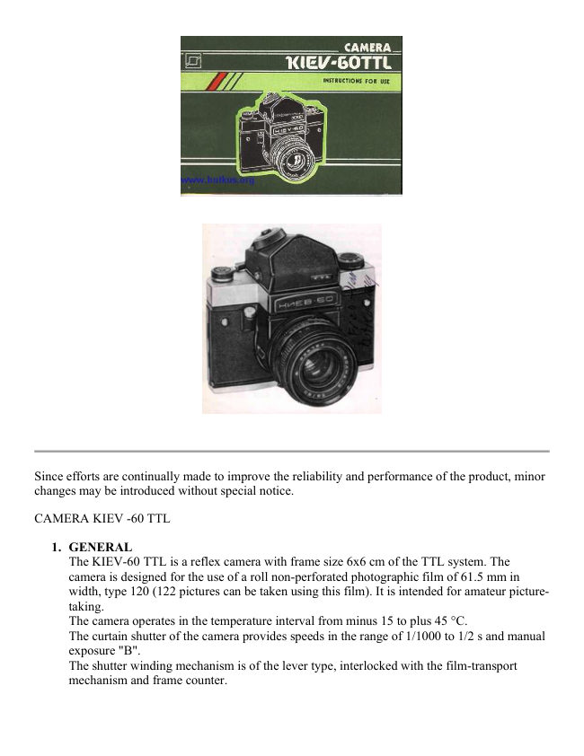
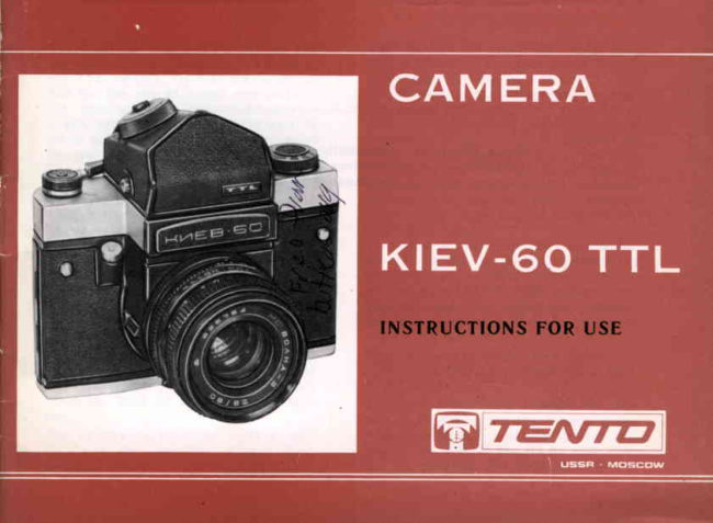
Kiev 60 TTL User manual
User manual for Kiev 60 TTL. 15 pages in English. Read the original PDF, download or print a copy without registration.
15 pagesEnglish1.8 MB PDF
Loading your manual…Open PDF directly
Document details
- Brand
- Kiev
- Model / document
- Kiev 60 TTL
- Document type
- User manual
- Language
- English
- Pages
- 15
- File size
- 1.8 MB
- Category
- Film cameras
- Document date
- Not specified in catalog
Search available document text
Find a term, then jump to its page in the original PDF. Image-only pages may not be searchable; check the PDF for exact wording and diagrams.
Page 2 · Read text
Since efforts are continually made to improve the reliability and performance of the product, minor
changes may be introduced without special notice.

CAMERA KIEV -60 TTL

   1. GENERAL
     The KIEV-60 TTL is a reflex camera with frame size 6x6 cm of the TTL system. The
      camera is designed for the use of a roll non-perforated photographic film of 61.5 mm in
      width, type 120 (122 pictures can be taken using this film). It is intended for amateur picture-
       taking.
     The camera operates in the temperature interval from minus 15 to plus 45 °C.
     The curtain shutter of the camera provides speeds in the range of 1/1000 to 1/2 s and manual
      exposure "B".
     The shutter winding mechanism is of the lever type, interlocked with the film-transport
     mechanism and frame counter.
View original page 2Page 3 · Read text
www.butkus.us

2. The camera is focused through a ground glass surface, microscreen and wedges located in
   the centre of the field of vision of the view finder. The back of the camera is thrown back on
   a hinge.
   The scale of the frame counter returns into its initial position automatically when the back of
   the camera is opened. The camera is provided with a synchronizer for operation with a flash
   lamp.
   The camera is outfitted with lens ARSAT C. The lens focal length is 80 mm, the relative
   aperture is L2.8, the diaphragm setting limit is 22. The lens is provided with the special
   multilayer coating (MC) which upgrades the image quality, enhances its contrast due to
    better integral transparence and reduced light dispersion of the lens.
   Provision is made in the camera for the use of change lenses produced for the KIEV-6C
   camera. Change lenses of the PENTACON SIX camera can also be used. The lenses are
   bayonet-attached and are fixed in position with a captive nut. Besides the TTL prismatic
   view finder the camera complete
    set comprises a view finder hood.

   The view finder hood enables the picture to be viewed on the ground glass with or without a
   magnifying lens and allows the use of the frame view finder for viewing. The field of vision
   of the view finder hood measures 53x53 mm.
   Magnification of the prismatic finder eyepiece is 2.5x, the field of vision measures 49x51.5
  mm. The field of vision sketch when operating with changeable view finders is shown in the
   Figure.
   The eyepiece design allows for application of diopter lenses. To install the diopter lens undo
   the clamping ring of eyepiece 39, set into the fitting socket a tens of 16 mm in diameter and
   fasten it by the clamping ring.


                                        The exposure time meter with light
                                                    indication determining the exposure time by
                                                   the light which have passed through the lens
                                                               is located in the housing of the prismatic
                                           view finder. Advantage and convenience of
                                                   the TTL measurement system is in
                                                automatic control of all factors affecting the
                                                value of the exposure time. The zone of
                                           measurement of the exposure time
                                              meter is in the central part of the view finder
                                                         field of vision and has an oval shape ( see
                                                   the Figure ).
                                         The exposure time meter ensures
                                            measurements in the range of brightness
                                           from 2 to 16 000 cd/m2, in this case the
                                                following values should be taken into
                                                 account: film-in-use speed (6 to 3200 units
                                                  of ISO), exposure time (1/1000 to 8 s) and
                                            diaphragm (1.4 ... 32).
                                                  76.
View original page 3Page 4 · Read text
A battery with initial voltage of 4 to 4.5 V (dia. 11.6 mm, length
                                 16.2 mm) is used as a power source of the exposure time meter.
                            The battery may comprise, for example, three cells type PX675,
                       RM675 or MS


2. LIST OF STANDARD
EQUIPMENT


Camera with lens ARSAT C 2.8/80,
prismatic view finder TTL with eye shade
and spool (set)                         1
View finder hood                       1
Light filters:                                        I
Y4)-IN (UV-1") or 0-2,8" (0-2.8")         1
)K3-1,4" (YG-1.4")                     1
Extension tube:                        1
20 mm long                           1
40 mm long                           1
Lens front cap                         1
Lens rear cap                          1
Blind cap for camera . . . .                1
Direct-type view finder cap . .             1
Carrying (shoulder) strap                1
Arm                                 1
Lens hood                            1
Carrying case                          1
Instructions for Use
Packing box
View original page 4Page 6 · Read text
20 - depth-of-field control
                                                             lever;
                                              21 - tripod socket;
                                              22 - take-up spool lock;
                                              23 - replaceable eye shade;
                                              24 - delivery spool lock;.
                                              25 - back lock.


4. OPERATING PROCEDURE
4.1 Loading
The camera can be loaded in the light (preferably in the shadow). Take the camera out of the
carrying case. Open back 17 having preliminarily shifted along the arrow up to the stop and
depressed button 25 located on the lower cover.


                                               Pull locks 22 and 24 by the clips, turn them
                                           counterclockwise and fix, this will bring centres 18
                                       and 19 down.
                                                  Insert the take-up spool into the right hand chamber
                                             of the camera so that the upper centre carrier fits its
                                                       slot. Holding the spool, introduce lower centre 18
                                                into its hole turning lock 22 clockwise.


Tear the paper tag off the leader end. Insert the spool with a film into the left-hand chamber of the
camera so that the carrier of the upper centre
enters the spool slot. Holding the spool and leader by a hand to prevent them against unfolding, put
lower centre 19 into the spool hole, turning lock 24 clockwise.
Thread the leader end into the take-up spool and turning the latter wind the leader onto it until the
mark on the leader aligns with the red index on the camera housing. To obtain the full specified
number of pictures on the film and to ensure operation of the frame counter observe the following
rules: when loading wind the leader tightly on the take-up spool; take measures against leader
skewness, creeping over the spool flange or crumpling leader edges; winding the shutter, take care
to bring the lever to the stop in one motion (do not wind the shutter, making several small turns of
the lever). Close the back pressing it to the camera until a click is heard.
View original page 6Page 7 · Read text
www.butkus.us

4.2. Preparing for Shooting
Make three blank shots to wind the leader onto the take-up spool. Now after the shutter is wound
the next time figure "l" will appear in frame counter window 11 which corresponds to the first
frame on the film. Set the film-in-use speed on scale 10, proceeding as follows: holding lever 1,
turn the disk until the loaded film speed value appears in the window. The film speed scale is given
in units of ISO.

4.3. Shooting


                                                Shooting with the camera consists of the
                                                  following steps:
                                                        shutter winding and film transport;
                                                 determining the exposure time (shutter speed
                                             and diaphragm);
                                                exposure time setting;
                                              diaphragm setting;
                                                     focusing;
                                             view finding;
                                                        shutter release.


Wind the shutter, turning lever 1 up to the stop. If the shutter is wound fully, the lever will
automatically return to the initial position, if not, it will remain in an intermediate position (in this
case it should be additionally wound). An incomplete winding of the shutter should be avoided. At
the beginning of wind the shutter a slight gradient of force applied to the lever may be fell. In
winding the shutter the film is wound through 0 one frame and the next number appears in the
frame counter window. The counter indicates the number of frames shot.
Determination of the exposure time is carried out with the shutter being wound.


                                               For determining the exposure time set on the
                                                       calculator the speed of the film loaded into the
                                             camera turning knob 31 until the film speed
                                                  value in units of ISO appears in window 32.
                                                Note: In connection with the introduction of a
                                       new series of the film sensitivity numbers
                                                 expressed in units of GOST/ISO it is essential
                                                       to use the Table given below in setting the
                                                    film sensitivity_ values on the calculator.
View original page 7Page 8 · Read text
Film sensitivity number of photographic
Scale marking,       material being used
GOST/ISO
                GOST/ISO (ASA)         DIN

6                     5: 6; 8                     9

12                  10; 12; t6                  12

25                  20; 25; 32                  15

50                  40; 50; 64                  18

100                 80; 100; 125                21

200                160; 200; 250               24

400                320; 400; 500               27

800                640; 800; 1000              30

1600               1250; 1600; 2000            33

3200               2500; 3200; 4000            36

Set on the calculator the lens speed turning scale 29 unlit the appropriate value
coincides with index 30.

The lens speed means the number corresponding to the maximum relative aperture. For example,
for lens ARSAT C - 2.8.
For determining the "exposure-diaphragm" pair corresponding to the shooting conditions do the
following procedures:
turn on the exposure time meter having depressed key 35 in the direction indicated by the arrow.
Upon turning on, release the key.


                                             The exposure meter will operate for 15s,
                                                      then it will automatically turn off;
                                                     observing through view finder eyepiece 39
                                                            sight the camera onto (he object of
                                                     shooting so that its image will arrange in
                                                         the ranges of the zone of measurement of
                                                         the view finder; in the field of vision of the
                                                view finder eyepiece You will see one of
                                                      red lighting signals: the left-hand signal -
                                                                        "little light" or the right-hand - "much
                                                                 light".
View original page 8Page 9 · Read text
www.butkus.us


                                             Slowly turn ring 26 up to the moment of
                                                       lighting of the second signal (if the left-hand
                                                      signal is lit - counterclockwise, if the right-
                                            hand clockwise).


Determination of the exposure time is carried out at simultaneous lighting of the signals; choose (he
"exposure-diaphragm" pair which is necessary for shooting on the calculator by exposure scale 27
and by diaphragm scale 29.

Note: In the event of the bright light the light should not be permitted, as far as possible, to
penetrate into the eyepiece. In this instance eye shades 38 and 23 should be used.

Set the chosen "exposure-diaphragm" values on the camera exposure time knob scale and on the
lens diaphragm scale.


Exposures maybe set both with the shutter released and winding turning knob 16 until the selected
number aligns with index 40 on the top cover. Setting of exposures from 1/1000 to 1/60 s with the
shutter released requires somewhat more effort than when the shutter is wound.
Manual exposure "B" setting should be accomplished by turning the knob clockwise only (between
shutter speeds 1/1000 s and "B" the ring is locked).

Set the diaphragm, turning ring 13 until the selected value aligns with the index on the stationary
ring. The scale is fixed at all diaphragm values.
Focusing either by the ground glass surface, microscreen and wedges or by the distance scale, is
accomplished, turning the ring with scale 15. Focusing can be carried out only with the shutter
wound, when the mirror is in the working position and the diaphragm the fully open.
View original page 9Page 10 · Read text
Depth of field is determined by the distance
                                                         scale with the aid of additional scale 14.
                                              Depth of field can be checked by the image
                                                       of the objects details on the ground glass
                                                       surface in the field of vision of the view
                                                            finder, after pressing lever 20 down to the
                                                            limit of its travel, then the lens will be
                                                diaphragmed to the opening set previously.
                                      When released, the lever will automatically
                                                         return to the initial position and the
                                                diaphragm will fully open.


                                             Depending on the definite conditions of the
                                                       picture shooting, sighting can be carried out
                                           by the use of the view finder hood.

                                       To replace the TTL prismatic view finder by
                                                     the view finder hood proceed as follows:
                                                      turn ring 43 clockwise until it aligns with
                                                  indexes 42 and 41. Depress buttons 12, lift the
                                   TTL prismatic view finder up;
                                                           set view finder hood 45 on the guide pins (in
                                                 so doing make certain that it is well secured
                                           on the camera).


                                             Open the view finder hood, turning
                                                              front wall 44 in the direction of the
                                                    arrow illustrated in the Figure. in its end
                                                            position the front wall of the hood is
                                                      locked and the side and rear walls are
                                                          automatically folded down. When lock
                                                            lever 46 is shifted up, view finder
                                                    magnifying lens 47 is set to the working
                                                              position.


Upon completion of shooting with the aid of the view finder hood, press the view finder
magnifying lens wall to the front wall of the view finder until the indexing lever snaps it in, then
fold up the side walls (first left-hand, then right-hand), then the rear wall, and holding the latter,
return the front wall into the initial position.
View original page 10Page 11 · Read text
www.butkus.us

In prompt shooting (such as sports photography) the view finder hood can be used as a simple
frame view finder. Then window 48 in the rear wall of the view finder hood will serve as one frame
and the window in the front wall, closed in the non-working position with cover 49, as the other.


                             The cover, when depressed, will turn and lock in the end
                                       position.
                                     In shooting with the frame view finder focusing is effected
                                        either by the use of lens distance scale 15 or by the ground
                                      glass through the eyepiece. To fold down the frame view
                                      finder depress the wall of view finder magnifying lens 47, in
                                          this case cover 49 will return to the initial position.


                                                    After folding down the frame view finder,
                                                     close the view finder hood as explained
                                                      previously.
                                       To release the camera shutter, gradually
                                                   depress release button 4 up to the stop.
                                              During this action the lens will close the
                                                diaphragm, the mirror automatically rises and
                                                      the shutter operates.


Shooting with exposures in excess of 1/30 s should be performed by the use of the tripod. The
tripod socket in the camera is provided with the 3/8"
thread.


                                      The shutter is released with the aid of the straight
                                               thread which is screwed into socket 3 of the release
                                           knob.
View original page 11Page 12 · Read text
4.4. Unloading the Camera

Shooting can be carried out until the "K" letter (end) appears in the frame counter window which
indicates that the film is used up. Then it is necessary to wind the remaining paper leader on the
take-up spool with the aid of the shutter winding lever. Since in this position the shutter winding
mechanism is disconnected, the release button may not be depressed each time after winding.
Upon completion of rewinding (when rewinding is over, the force applied to the winding lever
diminishes) open the back of the camera, move out the take-up spool centre and remove the spool
with the used film.


5. REPLACING THE LENS


                                           The camera is adapted for the use of
                                                    interchangeable lenses. To remove the lens
                                                       turn nut 6 counterclockwise up to the stop
                                              and disconnect the lens from the camera.


When installing the lens, it is necessary to fit it into the camera so that guide pin 51 of the lens gets
into slot 50 on the camera housing. Then turning the nut clockwise to the limit of its travel clamp
the lens on the housing.


                                     The following ARSAT C interchangeable lenses are
                                         produced for the KIEV-60 TTL camera:
View original page 12Page 13 · Read text
www.butkus.us


                                   Focal
                        Relative                Angle of field
Lens                                   length,
                        aperture                   of vision
                    mm

Wide-angle           1 : 3.5      30           180'

Wide-angle           1 : 3.5      45           83'

Wide -angle          1 3.5       65            66'

Long-focus                I 2.8       120          36'

Long-focus           1 : 2.8      150          28'

Long-focus           1 : 3.5      250          19'


6. FLASH PHOTOGRAPHY


                                                The KIEV-60 TTL camera is provided
                                                        with the synchro contact with
                                                              receptacle 54 for the connection of a
                                                                flash lamp. To install the flash lamp
                                                             the camera complete set is provided
                                                        with arm 52 which is fixed to the
                                                    camera housing with the aid of screw
                                                            53. Shooting with flash lamp is
                                                      performed with exposures from 1/30
                                                                to 1/2 s.


7. MACROPHOTOGRAPHY

Close-up photography of small objects (macrophotography) can be accomplished using rings
supplied with the camera in the set of spare parts and accessories. The use of the rings enables to
make shooting at a distance less than 0.6 m which is minimum for the ARSAT C 2.8/80 lens.

The rings are installed as required between the camera housing and the lens similarly to the
installation of interchangeable lenses. The rings can be attached together (in which case the
distance to the object will be the minimum and make up about 0.3 m).
View original page 13Page 14 · Read text
When operating with the view finder hood and when using the rings, increase the exposure time
found with the aid of the exposure meter in accordance with the data given in the Table.


                                                         Coefficient of increase of exposure time found with
Designation of ring fitted on the camera, mm            the aid of exposure meter (with lens distance scale set
                                                           to 0.6 m)

20                 2"
40                 3"
60
                     3.5"
(both rings together)

During operation with the TTL prismatic view finder influence of the rings on the value of the exposure time is
taken into account automatically.

8. INSTALLATION AND REPLACEMENT OF POWER SOURCE


                                         Unscrew lid 37 with the help of a coin installed
                                                      into the slot of the lid. Set the power source in
                                                 socket 36 locating it with its plus side to the lid
                                               (on the internal side of the cover mark "+" is
                                                 engraved).


9. USE OF LIGHT FILTERS
The camera set is provided with light filters used as attachments which can be screwed into the
front part of the lens mount (thread M62x0.75). The achromatic light filter YD-lx (UV-IX) is used
for weakening the effect of ultraviolet rays, for example, when taking pictures under high mountain
conditions, it is also helpful in colour photography.
Light filter 0-2,8X (0-2.8") is orange one, fully absorbs ultraviolet rays. It is used to obtain a
particular contrast in photographing the compositions with clouds, water surfaces, landscapes with
noticeable shading of verdure, etc. The light yellow-green filter 3K3-1,4= (YG-l,4") improves tone
reproduction of multicolour objects on high-sensitive photographic materials with a slight loss of
their sensitivity. With medium sensitive photographic materials the practically correct tone
reproduction of multicolour objects is attained.

10. CAMERA UPKEEP
The camera should be handled with care, kept clean, guarded against jolts, strikes, moisture and
abrupt temperature fluctuations.
View original page 14Page 15 · Read text
www.butkus.us

The camera should be kept in the closed carrying case. The lens should be closed with the cap and
the change view finder attachment should be in the case socket.
The lens should not be removed from the camera, if not necessary, so as to keep dust off the surface
of the optical parts. If the camera is stored without the lens, the aperture in the camera as well as the
lens should be closed with caps.
Wipe the surfaces of the optical parts with clean soft cloth or with cotton slightly wetted in rectified
spirit or ether.
When bringing the camera into a warm room from frosty weather do not
take it out of the case at once. Let it warm gradually (for two hours) in the case.
Do not exert excessive force in manipulating the camera. In case of some troubles or damage do not
attempt repairing the camera by yourself. The camera must be repaired or adjusted only by
specialists.
Important ! The camera curtains are made from light-tight rubberized fabric and to preserve it
against deterioration the following measures should be taken in shooting in the sun: remove the
lens cap and open the view finder hood immediately before shooting:
do not direct the camera lens towards the sun;
do not leave the camera in the sun during long-term outage between shootings.
View original page 15
Related documents and language editions
From the M. Butkus archive. Original publisher and archive notices are retained.
Check the model and edition against your equipment.
PDF verified 2026-10-10.