Film cameras
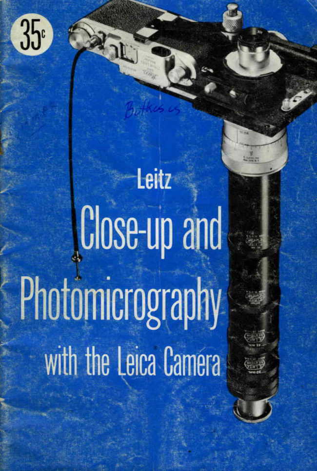
Leica close-up and Photomicrography User manual
User manual for Leica close-up and Photomicrography. 48 pages in English. Read the original PDF, download or print a copy without registration.
48 pagesEnglish6.3 MB PDF
Loading your manual…Open PDF directly
Document details
- Brand
- Leica
- Model / document
- Leica close-up and Photomicrography
- Document type
- User manual
- Language
- English
- Pages
- 48
- File size
- 6.3 MB
- Category
- Film cameras
- Document date
- Not specified in catalog
Search available document text
Find a term, then jump to its page in the original PDF. Image-only pages may not be searchable; check the PDF for exact wording and diagrams.
Page 7 · Read text
LEIIZ COPYING EGIUIPMENT


  r$Tithin recent years there has been wider recognition of the fact that the
miniature camera,which has already revolutionized the technique of amateur
and pictorial photography, has as much to contribute to the progressof the
working methodsof professionalphotographersof all kinds and thosepractic-
ing photography for  scientific purposes. Many amateurswho took up the
Leica merely as a means of pleasure and recreation made the discovery
that  it could also be an instrument of real value, by virtue of the series of
practical.accessorieswhich we have developedfor  it in the courseof time.
  Copying does not limit  itself to the reproduction of written matter and
drawings, but includesthe making of recordsof objectsof the most varied
kind and size, to produce negativesfor printing or enlarging in the usual
way or for projecting in the form of positives.Projectionis the best way of
presenting, to the public, printed reproductionsor lectures with lantern
slides, of objects which are not directly accessibleor are unavailable for
vlewrng.
  Miniature photography representsan important advance in  this line of
work. Its advantagelies in its ability not merely to produce large numbers of
negativesand positives at a minimum cost, but also to store and carry them
with the least possibleinconvenienceand to project them with small, light
and inexpensiveprojection equipment.
  The medical expert, lecturing to a conferenceon his work and having his
evidencein the form of large X-ray films, which are too valuable to be taken
along and indeed too large to be projected without special apparatusbeing
available,reproducesthese results by means of his Leica. An ample number
of positives can be taken anywhere,and easily projected onto a screento a
size of 8 x 12 ft.
  The historian or the handwriting expert may desire to show parts of an
old volume which he may neither remove from the archiveswhere it lies nor
exposeit to the strong illumination of powerful light-sources;he can, how-
ev-r, copy the folio p4ge by page without having to take it away, examine
either the negativesbr a positive strip at his. ease.at home with our desk
viewer, prepare enlargementsto any desired size with the Focomat Enlarger
and thus utilize them with the most successfulresults in journals or rnono-
graphs.Large numbersof scientificspecialistshave alreadyconvincedthem-
selvesof the value of this method. The very low cost of the negativematerial
eliminatesany question-and    of excessiveexPense.
  The botanist     the zoologist, the mineralogist and petrographer, the
archeologist,the entomologist and many other scientistshave similarly come
to appreciatethe advantagesof miniature photography.


                      www.butkus.us
View original page 7Page 8 · Read text
Oul copying devicesare not only suitable for scientificuse but are em-   .
ployed with great successfor commercialand industrial purpor.r. Tt.  value
of tttS photograpihc.processin duplicatingand, particulariy,in  tf,. wide field
ot advertrslngls evtdent,and thesemethodsare achievinggreat importance,
in fact, they have already achievedit.
Deftnilions: The                        pltotonticrograpby,nacropbotograpby,and mino-                 .termspbotograpby.are often-inter-used,mlsinieipreted,dr simlty     unJ.rstood.
These are the accepteddefinitions:                           "6i

  MrcnopsorocRApHy:  The rep.roductionof any object on a very minute
                         scale.The grainlessstrutture of a collodibn trans_
                      parencylends itself particularlywell to this work.
  MacnopnorocRAPHY: Photographsof small objects reproducedat nat-
                         ural or larger than natural size,-madewithout a
                      microscope.
  PuorourcRocRApHy: The.photographyof minute objectsby the use of
                      a microscopein conjunctionwith a camera.


           Figure  | . Mocrophotogroph,                                Figure 2. Photomicrogroph.
View original page 8Page 9 · Read text
THE FOCASTIDE
  You can make all types of close-up-flowerspictures with your Leic-acamera and
the Focaslide.  .  . from a cluster of      down to the head of a pin, to
reveal detail which normally cannot be seen.Copying, nature photography,
medical photography and a host of other picture-makingopportunitiesare
opened tb youl Gro"nd glass focusing is provided and the Focaslidecan be
used with  all Leica lenses.
How  lt Works: The principle behind the Focaslideis simple: it enablesthe
lens to be extendedolt from the camera,closer to the subject.This magni-
6es the image on the negative.The further the lens is extendedfrom the
camera,the greater is the image magnification.
  The Focasl-ideextendsthe lens appioximately12mm. from the camera.To
permit greaterseparationof lens from camera,a number of ExtensionTubes
ire auatrablein the following lengths: 7mrn., 1)mm., 30mm., 45mm.,60mm.
and 90mm. The Tubes can-be used singly, or together in tandem arrange-
ment, to provide a seriesof extensions.Thus, with the use of two 90mm.
and one 6bmm. ExtensionTubes,a subjectonly 3/L6 xl/32  inchescan be
made to  fill the entire negative area..
  The Adjustable Micrometer Extension Tube is the ideal adignct to the
 Focaslide,as it allows a wide range of Leica lensesto be used for copying
work. \Tithout adapters,it acceptsall Leica lensesand gives_a 20mm. range
 of adjustment between a 40mh. and {Omm. length of . Extension Tube.
 Micrometer indexing of the mount enablesaccuratesettings !o. h  main-
tained for varying scalesof copying work. Adapters are availablefor  all
90mm., l27mm. *a  r31 mm. Liica lensesto convertthe AdjustableMicrom-
 eter ExtensionTube into a short focusing mount for use at infinity.
  The Intermediate Focusing Mount insures crisp definition when photo-
graphing objects'slightsuch as manuscripts.It obviates.anydistortion..ofthe image        "the                     lateral displac6mentof the lens which will  occur if a i".   to
 Leica cameralEns, attacheddirectly to the Focaslide,is focused in  its free
 position.
  The large selectionof magnifiers facilitate rapid focusing of -obiectson
 the grounl glass screenof the Focaslide.Extreme accuracyof. foc.usingis
 assuied withi the 30x Magnifier by observing the air-image in the clear
 center-spotof the screen.
 How  to Mounf the Focoslide: The Focaslidecan be attachedto a Ball-
 Jointed Tripod Head which is, in turn, securedto a-steadytripod..The large
 ball-Jointed Tripod Head definitely insures freedom from vibration. Its
 improved and rilid  constructionpermits the camerato-be sw-ung.andposi-
 tivily  located at-any angle. Less than a quarter-turn of the thumb-screwto
 either left or right, s.*es  to releaseand lock the tripod screw instantly
 without effort.
   The Focaslide can also be attached to the sliding arm used as an offset
 support on a Leitz enlarger baseboardand upright.
    In either case,the Focailide is fastenedto iti mounting by a screw through
 one of its two threaded sockets(4) on the Fixed Plate (B).


                     www.butkus.us
View original page 9Page 10 · Read text
ll
                                                     ;f

                           eU
                                  &* r8


                                  17
                                      5


               Figvre 3. rhe Focoslide sliding  plote ond Fixed plote.

              Nomencloture for Figure 3.
A.  FocaslideSliding Plate               10. Cut-out for slow speeddial
B.  FocaslideFixed Plate                                       l l .  K n u r l e d n u t
 l.  Supporting post                      12. Retaining screw
 2.  Dovetai I grooves                     13. Leather-paddedspring clamp
 3.  Slotted krcking lever                  14. Camera positioning bar
 4. Threaded sockets                        I5.  Fixed stop
 5.  Leica lens thread                     16. Ground glass focusing screen
 6.  Lens flange seat                      17.  Locking-bar stop
 7.  Retaining screw                      18.  Parallel dovetail runners
 8.  Knurled screw                       19.  Dclvetail groove retainers
 9.  Rangefinder window recesses        20.  Aerial focusing clear spot
View original page 10Page 11 · Read text
Setting up the Focoslide: The Focaslideconsistsof a sliding plate (A),
           frg. 2, with parallel dovetail runners (18)  along its sides anda  fixed plate
              ( B )  with  parallel dovetail grooves  ( 19 ) . The  Focaslide is supplied with
         the two parts fitted together.


        socket (5)  of the fixed plate (B).
        Note:  Leica cameras having serial numbers lower than 400,000 are lmm.
         smaller than higher serial numbered cameras; therefore  it  is essential that


          Place the Focaslide in the position shown so that the ground glass focus-
         ing screen (16)   is at the right, and the lens flange seat (6)   is to the left.
          Loosen the knurled screw (8)  and push the camera positioning bar as far
          to the right as it will  go.
          Turn the knurled nut  ( 1 1 ) counter-clockwiseas far as it will go -   to the
         top of the supporting post ( 1 ) . Swing the  f eather padded spring clip  ( 13 )
          to the right or left so that  it will not be directly over the circular opehing of
         the lens flange seat ( 6 ) .
         The Leica camera and the lens are attached to the Focaslide separately.-body
         After  the lens has been unscrewed from  the camera, the camera        is
       mounted on the sliding plate (A).  The flange ring of the camera will   fit
          into the lens flange seat (6). The rangefinder windows of the Leica will  fall.
          into the recesses(9)  on the top of the sliding plate while the slow-speed


                     Figvre 1. Selling the shulter speed before oltoching the leico to the Focoslide.


                                Slow speed diol will
                              now operofe ol "Time"
10                          Cul-out for slow speed diol
                         Recesses for  ronge-finderwww.butkus.uswindows
View original page 11Page 12 · Read text
Align comero ond tighten
                         knurled knob
     Leother podded clomping bor
                                               \


                                                 =7
                                               -f-


                                                                                                              I r

                                                                                                                                                                                                                             ta


                              - S h u t t e r
                  m o y b e s e t f o r  " B u l b
                 exposure,  if preferred.
             Figvre 5.Clomping  lhe comero on lhe Focoslide with the Spring Clomp.

diat of  Leica or the slow-speed cover plate of  the Leica (Models  Ic and
IIc)  will  fall into the cut-out (10)  at the left end of the sliding plate.
  Set the top shutter speed dial to l/3o  second. The Slow Speed Dial  will
now_ operate at "Time,"  or the shutter may be set for  "Bulb"  exposure if
preferred.
  Swing the spring clip to a position directly over the back of the Leica
camera. Turn  the knurled screw clockwise, tightening the spring clip against
the camera. This holds the camera to the Focaslide.
   Still holding  the camera in  position, push the camera positioning bar
(14)  as far to the left as the camera permits  it to move, so that the forked
end of the positioning bar is securely against the camera body. Secure the
positioning bar by tightening the knurled screw (8)  in a clockwise direction.
  Screw the camera lens into the flange ring  ( 5 ) , from the underside of the
fixed plate  ( B ) .  If  intermediate extensior tubes are to be used, the male
end of the tube or series of tubes is screwed into the flange ring, where the
lens would normally go, while the lens screws into the threaded receptacle
at the other end of the tube or series of tubes.

                     Figvre 6. Aligning the comero with the Posifioning 8or.


                       Srrrg
            J3lrl9M
          rl!sl  lsur]
         UU'Oaltax       wj
                                                                     1 1
View original page 12Page 13 · Read text
Mognifiers for the Focoslide

   Five magnifiers are available to  facilitate focusing and image viewing on
the groutd  glass screen of the Focaslide. These are:
       5x Magnifier with focusing sleeve
       5x ruflide-Field Magnifier with focusing collar
          jx rvide-Field  Anlular  (90o)  Magnifier with  focusing collar
       4x tVide-Field Angular  (90o)  Image Reversing
          Magnifier with  focusing collar
       30x Magnifier with focusing sleeve


                                               Figvre 8. fhe 30x Mog nifier over lhe  cleor cenfer
 Figure 7. 5x Wide'Field  Angulor  (90')      spol  of  the  focusing  screen,  for  observotion  o(
      Mognifier  with focusing  collor.                                oeriol imoges.


                      www.butkus.us
View original page 13Page 14 · Read text
magnifier shows the image right  side up and correct as to  right and  left.
   The 30x magnifier is used where most critical focus is required-. It positions
 over the clear central spgt of  the ground glass and views ^n  aeriil image,
 the same as if the ground glass were removed from  the Focaslide.
   Mount  the magnifier  to be used over the ground  glass screen of  the
 Focaslide, using a rotating  motion  to engage lhe  bayonet flanges on  the
 base of  the magnifier  with  the bayonet catihes on  the collar  frolding  the
ground glass screen. Adjust  the focusing sleeve or collar of the magnifier
 until the cross lines in the central clear portion  of the focusing screen are
 sharp.            Leica lens is then focused until  the image viewed through the      -The
 magnifier  is sharp.
  When  using the low power magnifiers, the clear spot is ignored and the
 image focused on the ground portion  of  the screen.-\7'hen-using the 30x
                                        loyed. Correct focus  is assured when
                                                            r to the cross lines as the eye is moved
                                        arallax focusing.
                                              ld prevailing in close-up photography,
                               hragm at  full opening, stopping to a
                                      harp.


Figure 9. The four boyonet flonges of  the 5x          Figure 10. Ihe  lorge wide  field mognifier  is
     Magnifier    fit  the  boyonet  cofches.                    similorly  fitted  to fhe boyonet cofches.
View original page 14Page 15 · Read text
Figvre  Il.  tocking  lever ot  |ull lorword       Figvre 12. Locking lever oi  full bqck posilion
              position  lor  removing  sliding  plote.                           for focusing-

       Operoting the focking lever: When the Focaslideis supplieg,,1. slotted
         fr&irg   i.i.r  (3) has bEenpushedback as f ar as it *!J  go.,so that its curved
       end sn-uglyengages-directionthe stop ( 17) on the fixed plate.Th: sliding plate cannot
      move in- 6itn.".         *a  the ground glassscreenis positioneddirectly
       over the lens.
        The locking lever has three positions: pushed as far back as it will 8o;
        pulled forward as far as it will go, in which casethe sliding.plate can rnove
             itt two directions;a mid-way positionto which the locking lever can.be set.
        This latter position can be'"ielt"  through a springed stop in thg locking
        lever mechinism, and  it permits the sliding plate to be moved in one
        directiononly.
          Lubricate[n. parallel dovetail runners ( 18)     grooves ( 19) occasion-                                                 "qd                                                             as f ar as it                                                        locking          ally with Vaseline. By pulling forward the slotted                                                                                           l.y.l
             *iil  go, the sliding plite can be removed for cleaning and lubricating.


r4
                            www.butkus.us
View original page 15Page 16 · Read text
HOW TO USE THE FOCASTIDE


         In copy work it is necessaryto stop the diaphragmof the lens down to at
       leastf/6.3 in order to obtain-sufficientdepth 6f nefd. This, plus the fact that
      the use of extensiontubes.requiresincreised exposures,t.*ltr   in relatively
      long exposures.It  is thereforenecessaryto prevint vibiation of the copyin!
     equrpment.
        Center and focus                                 i{gg   that appearson the ground glass focusing                          1!e
     screenof the Sliding Plate.If the Focaslideis mounted"onthe Saseboardanil     upright of a Leitz enlarger,.through the use of a Sliding Arm, centering of
      the image                  best accomplisfredby moving the object ii, u. photograpf,ed.                    -is
                      done by moving                                             Focaslide to or  ui^y fiom the        .\oog! ^focusing.is                                               _th;
      subiect.If the baseboardand-uprigfrt-of a Leitz enlarger are being used in
      conjunctionwith a Sliding Al-,  this is simply u..o-flithed  by miving the
    Arm along the enlargerupright until the proper position is atiained.Vh.n
      the image.on the                              glass is                                                 ihuip,  ih.  l.nr  itself is critically                     .ground                                                .fairly     focused.This can be done by rotating the mount of the lens in the normal
     manner.
         After the image has been centeredand focusedon the ground glass screen,
                       lever on the Sliding Plate, to its inter'mediatelosition so      To::,th.-locking
      that the Plate will be free to move in only one direction. Move tire Plate in
      this "free" direction until  it is arrested                                            the fixed stop. The .r.lra  open-                                                                    !f      ing will-be directly over the lens and the exposure.^r, b. made.
      To refocus and recomPose.a new subject, rioue the Sliding Plate back so
      that the circularhousing-havingthe ground glass focusingscieenis over the
      lens. Pressthe locking lever asJar bi-ck as it"witt go so tfiat it fulty engages
      stop. Recomposeand refocus.
     lens Choice: For use with the Focaslide,the 50mm. Elmar lens is recom-
     mended.Leica lenseshaving rigid mounts can also be usedwith the Focaslide.
     Note: Becaate of  its tbicLnei,  the Focaslide acts lihe a 12mm. Extension
     Tube, so that the lens ased tuith it  i: further dwdy from tbe ftm plane tban it
     would. be if screweddirectly into. rbe camerale-nsopening, LensLsuitb  rigid
     moants cAnnot, tberefore, be                                 focased at  relatiaily  laige distances up  to       infnity.
              obiects with                                    thicknessare to be reproduced,the use      ,Vhen                         .appreciable
       l9nge1focal length lensesthan one of iOmm., suchas 9bmm., or L35rnm.,      9t
       is advisableto obtain betterperspective.
        tUfith longer focal                                 lenses, greater working distance is permitted         .                            .lengih
    between the lens and subject. convirsely, when  i-.nr.,  of  shor^terfocal
     length.are employed, the working distancebetweenthe lens a"d  r"bjeil
      ts shorter.


                                                          15
View original page 16Page 17 · Read text
EXTENSION TUBES


                                                                     90mm.


                                                                              | Smm.

                                         Figvre 13. fhere  ore 6 exlension lubes ovoilobfe.
               7mm.GTo permit greater separationof lens from camera, extension tubes are
       availabiein the followi"g lengths: 7rnm., 15rnrn., 3Ornrn.,45mm., 60rnm.,
      and 90mm. The tubes cin be-used singly, or together in tandem aff^nge'
       rnent, to provide ^ seriesof extensiogs.Thus-,with the use of two 90mm.
      and one 60-m. extensiontubes, L subject only ,/16  x 7 /t2  inches can be
     made to  fill the entire negative area.
    AD.IUSTABLEMECRONilETEREXTENSIONTUBE

       The Adiustable Micrometer ExtensionTube is engineeredwith the sarne
       precision ^r ^ focusing rnount for a Leica long-focus l.gt.   It  is the ideal
       ldjunct to the Focaslide,as it allows a wide iange of Leica lensesto be
       .5.d for copying work. Micrometer indexing of the mount enablesaccurate
       settings to bL riaintained for varying scaleJof copying work.


                                                                Adiusroble Microm eter Exlension Tube
                                                                      Flonge Ring


                                                                      Elmor50mm.lens


                           Figure  | 1. Extension tub e, flonge  ring and 50mm. Elmor lens.


 16
                             www.butkus.us
View original page 17Page 18 · Read text
\When used in conjunction with  the extension tubes as an adjustable
micrometerextension,it gives a 20mm. range of adiustment.
  tVith the flange ring supplied, it acceptsall Leica lensesin their normal
mount and offers a rangeof adjustmentfrom 40mm. to 60mm.
  Leica 50rnm. Iensesscrew directly into the flange ring of the micrometer
extensiontube. Adapters are availablefor all 90mm., L27mm., and 135mm.
Leica lenses.


and screwsdirectly into the tube.

                  D i r e c t i o n s i o r A i i g n m e n ?


          Figvre   | 5. Three sleps in oligning  lhe Adiustoble MicromelerMicromeler ExlensionExlension  f ube.

A. Screw the adjustablemicrometertube into the threaded flange of the
Focaslide,seatingit tightly and setting for the shortestextensionof 40mm.
The focusing index will possibly not align with the front of the Focaslide,
but at sorneintennediateposition.
B. Use a small jeweler's screwdriverand loosen the three counter-sunkset
screwsin the top knurled ring of the micrometertube. Turn the ring until
the focusing index is facing to the front of the Focaslide.Retighten the set
screws.
C. Loosen the three counter-sunkset screwsin the bottom knurled ring of
the micrometertube. Turn the ring until the L2 line is in alignment with                                       0the focusing index. Retighten the set screws.
  Care should be taken when making this adjustment that the focusing
mount is not moved. It should remain at its shortestextension.
  The adjustable micrometer tube may be taken off the Focaslide and re-
 placed as often as desiredwith complete assurancethat the focusing index
 will always align correctly.When using the micrometertube on another
 Focaslide,it may be necessaryto reset the index.


                                                           T7
View original page 18Page 20 · Read text
Formulo for Colculoring Exposure
wirh Extension Tubes

  \WhenExtensionTubes are usedon the Focaslidethe lens is moved further
^way from the film plane in the camera.This reducesthe relative amount of
light reaching the film so that an increaseof exposure is necessary.The
amount by which exposuremust be increasedover that required without
Extension Tubes may be calculatedfrom the following formula:
                            D '                             T^ -- F 2
Explanation of Symbols:
  T -  Exposure factor.
  D -  Distance from the lens to the film plane. This distanceincludes the
        focal length of the lens, plus the length of the Extension Tube or
      Tubes, plus the extension provided by the Focaslide (approx.
      12mm.)
  F -  The focal length of the lens used.
Eilmple:
  \7hat  is the exposure factor when using a 50mm. lens with a 45mm.
  extensiontube ?
      ExposureFactor-  Focal length of lens, plus length of exten-
                         sion tube  or  tubes, plus extension of
                       Focaslide            squared.
                       Focal length of lens   squared
 .      Amount of extension50 +  45  f  12mm. -  107mm.
                       1 0 7 X 1 0 7 -       r r , 4 4 g
                       50 x  50     2.500    4'6
              E*no,,,,5i;il,:Tf  x-atetY
  A quick referencetable giving exposurefactors as well as other essential
data when using 50mm. lensesand various Extension Tubes with the Foca-
slideis reproducedon the next page
  The table applies only to )0mm. Leica lenses. \Zith  lenses of  shorter
focal length, a given Extension Tube causesgreater relative image magni-
ficationthan it would with a 50mm. lens, and will require a correspondingly
greater increasein the exposure factor. \7ith  a lens of longer focal length
than 50mm., the same Extension Tube, will give rise to a relatively lower
imagemagnificationfactor than the 50mm. lens and will not require as great
an increasein exposureas that necessaryfor a 5Omm.lens.

                                                           rg
View original page 20Page 21 · Read text
Lens Adopters: Adapters are available for  all 90mm., I27mm. and Brmm.
   Leica lenses to convert the ad justable micrometer extension tube into a short
   focusing mount for use at infinity. The versatility of this accessoryis exten-
  ded by these four adapter rings which accept the lens components of the
   following  lenses: the 9Omm. Elmar   f /4;  9bmm.,  f /a.5  ; l27mm.,   f /4.5  ;
  and the I35mm. Hektor  f /4.5  (long-focus) lens.
    Vhen  using the 90mm. Leica lens component.s, the flange ring  at the
  end of the adjustable micrometer extension tube must be removed by un-
   screwing in a counter-clockwise direction. The adapter is then inserted in
    its place. Then mount the lens component to the adapter.


                                     90mm.  f /1, Focusing Mount


                                                                 90mm.  f / 4.5 Focusing Mount


Adiusfoble
 Micrometer
Exlension
T ube


                                                                               Adopler Rings


                                                                     Elmorg0mm.f/1lens


                                         FIonge Ring


        Figvre 17.The flonge ring must be removed before fitting either of the two 90mm. lens odoplers
                                         lo the Adivstoble Micromeler Extension fube.

20
                             www.butkus.us
View original page 21Page 24 · Read text
* 1
   (


                      Figure  19. Set up  lor  copying docu-
                     menfs. lomps  (no]  visible in  pictvre)
                     should be  of sorne power ond  egui-
                         distanlly spoced for even illuminolion
                                       ol the monvscripl.


                 bI
View original page 24Page 25 · Read text
Etposure Colculotion: To apply an exposurefactor (ur determinedby the
formula)   it  is first necessaryto determine the "norrnal" exposure for the
subject. !7ith  small subjects this presents a difficulty when using a photo-
electric exposure meter, for the subject may be the same size, or even smaller
than the cell window  of  the meter. The problem can be solved by  first
arranging the  lighting  units  for  properly  illuminating  the subject, then
substituting for the latter a card which  is approximately the same shade as
the subject. The exposure meter reading is then made of  this card.
  To insure that a well exposed negative is obtained, it i.s recommended that
a serie.sof exposures be given on each subject. At  least three exposures
should be made: one, the exposure calculated; the second, double the calcu-
 lated exposure; and the third, half  of the calculated.exposurg,.For greater
 insurance, a fir'e-exposurestrip is recommended, with  in addition to the
exposures mentioned includes exposures representing four times and one-
quarter of the determined exposure. \When darkroom facilities are available,
 single exposurescan be made and checked.
Film Choice: In close-up and copy work  it is usually necessaryto reproduc,:
as fine detail a.spossible. This calls for the use of fine-grain films, since the
 finer the inherent grain in the film, the greater is the ability of the film to
 reproduce detail.
   For this purpose the finer grain 31mm. films may be divided into two types:
   a. Medium speed, fine grain films:-Examples  of such films ate DuPont
      Superior No.  1, Eastman Panatomic X, and Ansco Irinopan.
   b. Slow speed, extreme fine grain films'-Examples  of such films are East-
    man Microfile, Ansco Minipan and DuPont Microcopy.
                                              Iror general work the medium speed
                                         films are recommended. They have good
                                     latituCe and are capableof reproducing
                                                           \il7hen maps, charts,                                      delicate gradations.
                                           etc., are to be copied, in which case
                                  "speed" of the film may not be essen-
                                                  tial, the slow speed films  are recom-
                             mended because of  their  ability  to  re-
                                    solve finc detail. In those cases wherc
                                    only black and white  charts, etc., arc
                                          to be copied, positive film can be em-
                                      1-,loyed.This film  is ordinarily used to
                             make film  positives from 35mm. nega-
                                        tives. It  is relatively cheaper in  pricc
                                   than negative film and can be employed
                                            in copy work where no colored material
                                               is to be copied.
                                            In tho.secaseswhere moving objects
                                             irre encountered, which would necessi-
                                       tate relatively high  shutter speeds, it
                             may be necessaryto use high speed films.

                                          Figure 20. Locking pin on wire releose leoves hond
                                                                                    f ree for long exposures when shuller is operoled on
                                                              bulb selting.

                     www.butkus.us24
View original page 25Page 26 · Read text
Figure 2l  . Typicol sef-up for "Quiz"  picfures. For this typ.  of
               work o smoll spollighf  is ideol.
View original page 26Page 27 · Read text
INTERMEDIATEFOCUSING MOUNT


         The Intermediate Focusing Mount  is a valued copying accessory,attaching
          to the bayonet flhnges of  the Leica 50mm.  lenses, thus ensuring a  rigid
        mounting.  It also prevents any possible distortion of the image due to the
          slight  lateral displacement of  the lens, which may occur when  the Leica
       50mm,  lens, attached directly  to  the Focaslide or  the extension tube  is
        focused in  its free position. The Intermediate Focusing Mount gives a wide
        range of  picture-taking  possibilities. \When  it  is attached directly to  the
        Focaslide and the 50mm. Elmar or Summitar lenses, it makes possible the
        photography of objects at distances from  infinity  to LrrA inches, from  the
        back of  the camera to  the object. A   ,  x  7Vz-inch area is covered at  the
        closest distance. Still smaller areas are easily covered by inserting any of the
        extension tubes between the lens and the Focaslide. The Intermediate Focus-
         ing Mount  gives ^  r'ariable extension of 7.5mm. and can be used as  r
        focusing aid for fine adjustments.


            Figvre 22. Boyonet flonges of 50mm. lens ossembly engoge  the boyonet colches of the
                                          lntermediole Focusing Mount.


26
                              www.butkus.us
View original page 27Page 28 · Read text
-b


                                                                          -/a


                                             I


Figure  23. The compensoting   ring   is detoch ed  when  lens  in  the  lntermediole   Focusing  Mount
                                                           is used  of  infinity.


the Intermcdiatc Irocusing Mor-rnt in  a. counter-clockwisedircction. Attach
thc rnount, u'ithout thc  iit'rg, directly to thc lens thrcad of the lrocaslide.
Turn focusing rnoLrntout for sliding clcarancethcn back to ProPcr setting.


                                                             2
View original page 28Page 29 · Read text
OPTICAT SHORT DISTANCE
     FOCUSING DEVICE


           The  Optical  Short Distance-Focusing Device  for  the Leica enables the
           automatic focusing of  the Leica lenses to be utilized  for  close-ups under
           3.5  ft. \7ith  this device, all object distances between 3.5  ft. and l,6Yz in. to
           the.plane of the film (back of camera) can be set with  rapidity and accuracy.
        One  is not confined to some predetermined focusing distances (as with our
            setting devices for the use with  front lenses and intermediate collars), but can
            set the lens continuously to ali distances between the limits quoted. The ratio
            of image varies from 17.5 X  to 6.3  \   minification, the size of object from
           t6y2" x247/to"   to 'Yr.o" X  8t/r,o" G2 X  63cm. to 15 X  221/2cm.). The
          device consists of  an  intermediate  helical  focusing  arrangement which
              is screwed into the lens changing flange of the Leica. This accessoryhas an
            optical glass wedge, which  positions in  front  of  the rangefinder window
           pioviding  the necessary deflection of the rays. A square stop which  fits in
            front  of the viewfinder, which, by means of a cam movement, provides auto-
           matic compensation  for  parallax, and  the reduced  field  of  view.  Bayonet
          catches in the optical short distance device engage the bayonet flange of the
           lens when  it is inserted. Onlv )Omm. lenses can be used and two models are
         made, one  to accept the Elmar 50mm.  (Noorv)   and the other  for  the
          Hektor, Summar and Summitar )0mm. lenses (Noorv'nrsuu).
           \When focusing with  the device, only the middle of the field of the range
          should be used.


     OPTICAL NEAR. FOCUSING DEVICE


           oMIFo is a near focusing device similar to Nootcv except that  it offers a
           fixed focus with a fixed ratio of  L:4, covering approximately 4x6 inches.
                 It is designedto accommodatethe 90mm. Elmar f /4lens. This combination
           affordsa greaterworking distancethan the 5Omm.lens usedwith the Nooky.
           The device consistsof an intermediate mount which is screwed into the
           lens changing flange of the Leica. In  addition, the mount accommodates
            optical wedges that position in front of both rangefinder windows, and a
          diminished stop in  front  of  the viewfinder window. This arrangement
          pqovidesthe neiessarydeflectionof rays and permits critical focus, as well as
           indicating the correct field of view. The lens must be focused at infinity.


r 2 8
                               www.butkus.us
View original page 29From the M. Butkus archive. Original publisher and archive notices are retained.
Check the model and edition against your equipment.
PDF verified 2026-10-10.