Film cameras
Leica IIIa User manual
User manual for Leica IIIa. 61 pages in English. Read the original PDF, download or print a copy without registration.
61 pagesEnglish8.0 MB PDF
Loading your manual…Open PDF directly
Document details
- Brand
- Leica
- Model / document
- Leica IIIa
- Document type
- User manual
- Language
- English
- Pages
- 61
- File size
- 8.0 MB
- Category
- Film cameras
- Document date
- Not specified in catalog
Search available document text
Find a term, then jump to its page in the original PDF. Image-only pages may not be searchable; check the PDF for exact wording and diagrams.
Page 2 · Read text
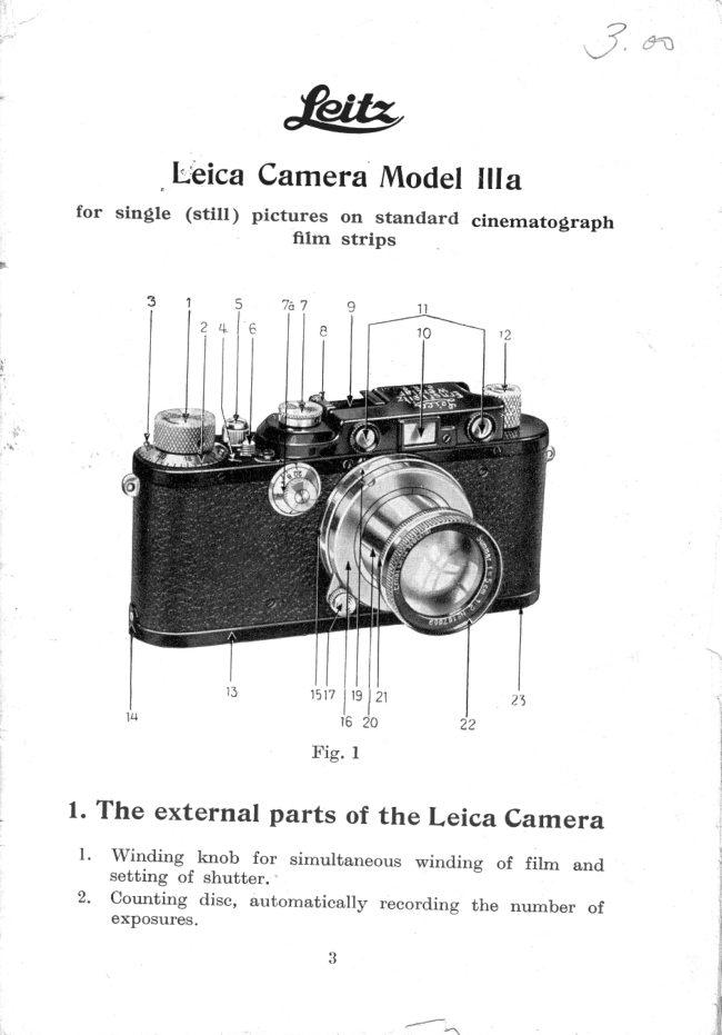
Ir'bica Carnera Model llla
 for  single   (sti[                            )  pictures  on  standard  cinernatograph
                                     filrn  strips


              z4le


                          1517l19 lZl
                               16 20
                                 Fig.   I

1. The external parts of the Leica camera
  l.  Winding  knob  for  simultaneous  winding-o  of  film  and                                   -     setting  of shutter.
 2'  counting  disc, automaticaily  recording the number  of     exposures.


                                                                  --{:     ra
View original page 2Page 3 · Read text
3.  One of the two lugs by means of which  the counting  disc
       is turned  anti-clockwise  and against the direction  of the
     arrow  on the winding  knob  for  zero setting.
 4,  Counting  An'ow,  indicating  the nurnber  of photographs
      taken.
 5.  Press Button,  to which may be screwed a Wire  Release
      (after  the  milled  protective  ring has been removed).
  6.  Reversing Lever for engaging (towards A) and disengaging
     (towards R,) the automat,ic coupling  of film advance and
      shutter mechanism before and after exposures have been
    made  (before re-winding   film).
 7.   Shuttor-speed  Dial,  for adjustment,  of speed required  (to
     be set, after winding  of shutter)   -  See (f).
 7a. Adjusting   dial  for  the  slow instantaneous  speeds fr.om
       l-1/,   sec.
 8.  Index  Arrow,  for figures of Speed Dial  (Z).
 9.   CIip,  to hold  Universal  View-finder,   etc.
10.  View-finder  showing  size of image.                                                                                              I                                                                                                                           it 1.  The two Object Glassesof the Range Finder, the mechanism
      of which  is interconnected  with  the focusins mount, of the
     lens.                                                                                                                                                           I
12.  Back-winding   l(nob  (extensible)  to wind  the  film  back
      into  spool chamber  after  exposure.
13.  Camera Lid.                                                                        I
14.  Pin over which the camera lid  is hooked at, one end. (See
     also 23.)
15.  Lens changing  flange  for interchange  of Leica lenses of
     various  focal  lengths.
16.  Distance  Scale. (Not  visible.)
17.  Lens focusing lever with  catch for  infinity,  actuating  the
     adjustment   of range  finder  and focusing  of lens simul-
     taneously  (index  not  visible  in  illustration).
19.  Depth  of focus  collar.  (Scale not  visible, see Fig.    f .)                                                                                                  I20.  Tubular   Socket, of  Lens,  to  be  pulled  out  for  photo-
     graphing, when the lens is locked  in a bayonet  catch by
      turning    it  to  the  right  (clockwise).
2t.  Ring  or lever  with  index  line  for  adjusting  aperture.                                                     \22.  Front  of lens mount,.
23.  Swivel  (not  visible)  for opening and closing camera  lid
     (see Fig. 2).


                    www.orphancameras.com
                              -Z
View original page 3Page 4 · Read text
2. Opening the Leica Camera


  ,,14*


                                         T'tg. 2


    Turn  the             _camera upside  down  and  open  lid  13 by"asraisingswrvel  23  a\d   turling   same  frorn  "closedr'   t,o "open"       far  as
it  will  go.   Lift    lid  and  then  unhook    at, pin   14:

                                           B
                                     BB gs 87


                               Fig. 3


   The   interior   then   presents   the  appearanee   as shown   in
F ig. 3. Now  withdraw   the spool cham6ei  B hy  the milled  knob

                                5
View original page 4Page 5 · Read text
B. The Leic,,afspool Chamber Model B
              1. Its Components

                             g 7  B 6


                                8 2                  B 3
                                Fig.  4 and  5


                    B    -  Complete  Spool Chamber  Model  B
                      81   -  Outer   Shell
                      82 _-  Inner   Shell
                    B3  -  Cent,re  Spool
                   B 4 -   Slot  of  Centre  Spool
                      85   -  Milled   l(nob   of Centre Spool
                   B 6 -  Slots  of  Spool Chamber
                    B7  -  I(nob   of  Spool Chamber
                      88   -  Safety  Spring


   The  Leica Charnber  Model  B  is  of  cylind.r'ical  form  and
consist,s of three components:  the  Outer   shell  B 1, the  fnner
shell B',  and the cent,re spool B3.


                    www.orphancameras.com
View original page 5Page 6 · Read text
Th", guide-groove   on the  inner  shell and  the  pin  inside  the
  out'er  shell  (oppgsite_ the  safety  spring,  which   is Lot   .risinte  i1
  illustratlol)    m-aXe  the  openidg   and "closing-   of  the  charrrber,
 mechanical.


          Fig. 6.  Leica spool chamber Mocler B open


   As will be seen in the illustration,   tr'ig. 6, the guid,e-groove
 first  runs along the inner  shell and then Te"-inad-   ilaosemi-
 circle       at the            upper                            of                           the shell.                               The                                            guide-pir  ofTn"                                                            outer                         "iot shell then           constrains                       the                           inner                                    shell to                                         be"mo.r"'d                                                                               lle                                                                         slot
in the required manner,  thus:                       "fotrg
       l.  Int,roduce the inner  shell with  spool in the outer  shell
        until  its rim comes.to a.gtop, thd  slot openincJ  neirg
      then  one above  the  othei;
    2. Turn  inner  shell  to the  left  (anti-clockwise                                                                                      ) up to       the limit  stop, when the safety ipring  will  th;6ngu,g".
,. ^ .Agaip, the chamber can  olly  be opened by  first  slightly
             safety- spring,, turnin[   the  iirner  sfr"if  il-;il-?ighttif,ting  !h"
(clockwise), and then wilhdrawinlg  it,  i.e. by going throueh the
same process in  exactly  the reverse order". fs"""Fig.   z j   lr;-
View original page 6Page 7 · Read text
2. Loading Spool Champer Model B
          by subdued daylight

               (Daylight   loading   filrn  spools  )


     Fig.  7.  I{ow   the  spool  chamber  B  should  be opened


 l . Open  Spool  Chamber.   To  this  end  release  with   the  index
    finger   of  the   left, hand   the  safety   spring  B 8 by  pulling      it
   backwards    (Fig.  7) and  turn  the  inner   shell  with   the  right
   hand  at  the  knob  towards   the  right   (clockwise),   to  the  end
    of  the  movement.   Then  withdraw    inner   shell.
.) Remove   the   cent're  spool  from   the  inner   shell  and  keep    it
   as   it   is  only  required    for  darkroom    loading.


                   www.orphancameras.com
View original page 7Page 9 · Read text
Fig. 10


5. Close spool chamber  by  giving  the  inner   shell  half  a turn   to
   the  left,  when  the  safety  spring   wiII  engage  at  the  rnark  Z;
   now  withdraw   the  paper  strip  only,  holding   the  film  so that,
      it  does  not, come  out, together   with   the  paper.
6.  If  the loaded chamber  is not  to be used  in  the camera  imme-
    diately,      it  should  be  kept   in  the  aluminium    container   so
    that    it   is  not  exposed   to  daylight   too  long.  With   highly
    sensitive   Leica   films   the  projecting    beginning    of  the  film
   conducts   the  light   into  the  spool  chamber  and  thus  causes
   fogging.   This   is not  the  case  with  backed   films   or  films
   having  an  intermediate    layer  against   halo.  For  this  reason
   we  particularly   commend   these  brands.
    Daylight    loading   Leica   films  are  supplied   by  Mimosa  and
Gevaert,   each  spool   containing    a, film   strip    5'l n  ft.   long,
sufficient,   for  36  exposures   of  the  Leica   size  24 X 36 mm.
Il,e Agfa  and  Perutz   Leica  cartridges   see below.
   Loading     of   camera,    exposures    and   unloadin$      of
camera,   see pages  15-19.


           3. The Leica sarttidges
              for  daylight   loading  and  unloadin$

   The  Leica  spool  chamber   Model  B  ,*a,y  be  loaded   into
the  camera   in  daylight   and  rnay  also  be  removed   in  dry-
light,  but  the  film  cannot  be taken  out  of  the  spool  chamber

                            1 0


                  www.orphancameras.com
View original page 9Page 10 · Read text
in,  daylight,   so  that   in  special  circumstances    one may  need
a larger  n-umper  of spool  charnbers   in  ord.er to avoid  unl"oading
them  in  the darkroom.
     In such cases, the Leica  cartrid.ges  of Messrs. Agfa, Gev aert,
Hauff,   I(odak  and Perutz  provide   a"satisfacto"y    *oi'otion.  These
                  t4gir   films.  in  special  Leica   car"tridges   for  d*y-fit3*,supply       loadi_ng.  Thg  cartridg"                                 used  once  only  aila  is openeclligrt-t                                                           .i.in  the  darkroom    for  developing   the   film.
   The  loading.  of  !h"  Leica  cartridges   into  the  camera,  and
also the  unloading,   is-done  in  the  sant_e way  as a loaded  spool
chamber  Model  B.    tr'or  further   details   *"6  pages   lb-lg:
    Please   note.   Leica  cameras  which  are  not  yet  equipped
with   the  lock  v2  (see  Fig.   lJ  I must,  have   this   frart   rittea     if
the  Leica  eart,ridges  are  io  be  used.


                          v2     D

                              Fig.  I I


                           1 l
View original page 10Page 11 · Read text
4. Loading of Film Chamber Model B
               in the darkroom

     (In  this  case darkroom   loading   film  spools  are  used)


                             Fig. L2
    I{ow  the spool chamber Model B should be opened


l . Open spool chamber.  To  this end release with  the index
   finger  of the  left hand  the  safety spring B 8 by  pulling    it
  backwards  (Fig. 12) and turn  the inner  shell with  the right
  hand  at the knob towards  the  right  (clockwise) to the end
   of the movement,.  Then withdraw  inner  shell.
()  Remove the  cent,re spool from  the inner  shell.  Ta$e the
   wrapping  off the  film.
                        T2


                    www.orphancameras.com
View original page 11Page 12 · Read text
3. Thread  the  short tapered end  of the  film  in  the  slot B 4
   of the centre spool BB (emulsion side next  to the arrow)   itt
   the  direction  of the  arrow.
1. Wind  film  on centre spool moderately  tight,  emulsion side
   inward, and  if possiblC use hand film winder  or mechanical
   winder.  Take care Lhat emulsion  is not  touched.


                   88*


                                                                                                                                                                ,.   ''""'I,

                              Fig. T4

5. Introduce  film  spool int,o the inner  shell, milled knob  first,
   the beginning  of the  filrn  lying  in  the  slot'.
                          r3
View original page 12Page 13 · Read text
l'ig.  15

6. Put  both  together  int,o  the  outer   shell,  superimposing the
   two slots. Pull out the  beginning   of the  fihn about 2 inches
   t'hrough the open  slots.


                           Fig 16


7. Close spool chamber by giving the inner shell half a turn  to
   the  left, until  the  safety  spring engages at, Z.
8. Pull  out, the beginning  of the film  about, 2 to 3 inches from
   the closed spool chamber, so that   it does not,  slip back.
9.  If  the loaded chamber  is not, immediately  inserted  into  the
  camera  it should be kept  in the alurninium  container  after
   the project,ing piece has been wound around  the chamber.

                          L4


                    www.orphancameras.com
View original page 13Page 14 · Read text
Ct. Loading
    of the Qarnera in subdued daylight


                           1517l 19121
                              16 20

                            Fig. L7


    Note.  The loading  of the camera should be done in sub-
dued daylight  and the  slot, of the chamber  should be covered
yp       well as possible.  The chamber should not be exposed to   ?F
daylight   longer  than   is  absolutely  neeessary  for  loa-ding.
l.  Set, the  reversing  lever  6 from R  to  A.
2. Wind  the knob    I  once and release press button   5.
                          15
View original page 14Page 15 · Read text
Fig. 18

3. The  c&mera  having  been  already  opened  as per  Fig.  2 and
    t'he  withdrawrl    spool  chamber   loaded,  now  withdraw    also
    the  receiving  spool M  (counter   spool).
             f.4M. B


                             Fig. tg

4. Hold receiving spool M with  left hand and the loaded cham-
   ber B in the right, as shown in Fig. 19. Clamp the beginning
   of the  film  (ernulsion   side  outwards   ) under  the  spring
  Ml  of the receiving spool. (The perforated edge of the film
   should  lie  right  against  the  flange  with  knob.)  Do  not,,
   however, wind  film   orr.. The  tapering  of the  film  should
   begin close to  the  slot, of the chamber.
                         r6


                  www.orphancameras.com
View original page 15Page 17 · Read text
Fig. 22


6. Hook camera lid 13 (swivel 23 set to "open")  over pin  14.
   Close lid and
FIl .  Turn  swivel 23  right  over  to  "closed".
8. Wind  knob  1 once and  release press button.  Repeat, this
   once rnore.  (This in order  to dispose of the useless tapered
   beginning  of  film.  )
9. Turn  countirg  disc 2 by means  of the two  lugs 3 towards
   the left  (i. e. against the direction  of the arrow of the winditg
  knob  1) to 0 position.


                                                           I 8


                  www.orphancameras.com
View original page 17Page 18 · Read text
D. Taking  the Photograph

   l.  Pull out lens, and turn  it to the right  (clockwise)   so as
     to  lock   it  in  the bayonet  catch.
  2. Adjust  iris diaphragm by means of lever or ring 2l  (Fig.22).
  3. Wind  knob   I  in  direction   of arrow  right  to  stop.
  4. see that  sh'tter  speed is correct  or set  it by  lifting  the
    speed  dial  7,  at  the same time  turnine     it "so thaf,  the
     required.ligure  lies                           lgainst  the index arro*  8.  Let go knob
    which  will then settle in position.  At z  t]ne shutter iemains
    open as long as the button   is pressed down.
4a. see further remarks page 28 re Leica Mod.el rrr and rrra.
  5. sight-the  objec-t through range  filder    ll,  turning  focusing
    lever 17 or the lens mount 22 .onril the two imasei  coincidE
     (fuse into one). rJse view-finder  10 to view the"whore field
    and  gently.  (not  jerkily)   release press trutton   b.  When
    photographing_ rapidly  rnoving  objects  the  range  finder
    should be used as view-finder.

         E. Unloading of Camera
             in subdued daylight
  l. Release once again  press button  b  (whether  knob    I   is
   wound  or not).
 2. Set reversing  lever 6 from A  to R.
 3. Pull  out back-winding  knob  12 and turn  in  direction  of
    arrow until a resistance is felt and wind over this resistance.
    (This means that the end of the film comes off the spring of
    the receiving  spool.)  Give about two more turns  lirre tTtm     is now  all wound back  into  the spool chamber).
 4. Turn  swivel 23  of camera  lid  13 towards  the  reft from
    "closed"  t,o "open"  and remove camera  lid.
 5. Pull  out spool chamber by means of the milled. knob and
   keep  in aluminium   container  for  developing.
 6. The removing.  of the  film  from  the  spool chamber must
    g-+ly.be done in_ the darkroom,  as desdribed. under B 4,  l.
   The  inner  spool with  the  film   is then removed and  ihe
    film wound  off.

                                                                      l 9
View original page 18Page 19 · Read text
F. The "Standard"  Leisa Camera

   The  foregoing  instruct,ions   for  the  Leica  camera Model   III  a
apply  to  the  "St,andard"   Leica  also,  except, where  reference   is
made to the rangefinder  and the adjusting   dial for the slow speeds.
                                                          In  the  " Standard"
                                                 Letca,  the  rangefinder
                                                             is   not'  coupled   with
                                                the  lens.
                                                           In the clamp  which
                                                             will   be     f ound   near
                                                the  viewfinder    of  the
                                                                     " Standard"    Lerca,   a
                                                special  small  holder   is
                                                  inserted,   in which  the
                                             short-base  rangefinder
                                                             is   fixed   horizontallv
                                                bry means  of  a, pin.
                                     When     it  is desired
                                                      to  adjust   the  time  of
                                          exposure    it  is only  ne-
                Fig. 23                     cessary,   in   order   to
                                               obtain   access  to  the
speed  dial,  to push  forward   the  right-hand   end  of  the  range-
finder   (see Fig.  24), and  after  the  adjustment   has been made
to  return     it  to   its  original   position   as  far  as the  stop.
   Now  look  through   the  rangefinder   and  turn   the  dial  until
the  two  images  which  are  visible  therein   coincide.   Read  the
                                           distance  figure,  then  ad-
                                                    just  the index  line  of the
                                              lens  focusing  mount,   to
                                                    this  figure, wherupon  the
                                       exposure  may  be made.
                                              For  shorter  distances
                                        proceed  in  the  followins
                                       manner.
                                                Adjust   the  index   of
                                             the rangefinder  as well as
                                              the   lens   rnount     right
                F.ig. 24                 away  to  the  desired  dis-
                                          tance  (for  instance,  6  ft.
in the case of portraits).   Then approach  or retire  frorn the object
until  the  two  images  which   a,re visible   in  the  finder   coincide.
       It  should  be mentioned   thab  the  rangefinder   rnay  also  be
used  in a vertical   position.   To do  this  remove  the  holder  from
the  clarnp. and  insert   in  the  latter   the  flange  which   is on  the
eyepiece  side.
                       20


                    www.orphancameras.com
View original page 19Page 20 · Read text
C. Some additional hints on the use
                 of the Leica
                     Leitz   Trirnrnin$      Ternplate
enables  the  film  to be correctly  shaped,  and  its use also results
in  the  saving   of  film.    It   is onlv  required    if  film   is cut  from  a
long  length,  or when  the exposed  part  of a filrn  has been cut, off ,
and the  rest  is to be reloaded  into  the camera.


                                 Fig. 25.
                              trilrn  Trimming    Template
              ('I'rirnming   the  film   for  the  centre  spool)

   When   using  cut  lengths   of  filrns  as  supplied   by  various
firms,  special  trirnrning    is  not  necessary.  On  the  other  hand,
when  film   strips  are  cut  as required  from  a long  length  ) cate
must,  be  taken   that   the  two  ends  of  the   film   are  correctly
t,rimmed,  as  this   is  absolutely   necessary    f or  the  satisfactory
working    of  the  film  winding   rnechanism    in  the  camera.   For
this purpose   it  is advisable  to use our new Trimming   Template,
which   also  rneans  a, saving   in  film  as compared   with   earlier
mod.els.
    At  the  beginning   of the  roll  of film  make  the wedge-shaped
cut,  for  the  centre  spool  and  rneasure   off  the  required   length
of film.   At  the end  of this rnake  the curved  cut, for the  receiving

                            2L
View original page 20Page 21 · Read text
spool.  When  doing   this  there   is rnade  at  the same  tirne  the
correct,  cut,  for  the  receiving   spool'on   the  remaining    film  on
the   roll.     It   is  therefore   not, necessary,  as was  the  case with
our  previous  Trimming   Templates,   to  trim   the  next,  length   of
film  taken   frorn  the  rol1, so that   in  this  wayu about  4  ins.  of
film  are  saved. on  every   strip   .
   The  manipulation    of the  Trirnming   Template   is as follows:
   To  t,rim  the  film  for  the  centre  spool,  unfold  the  Trimrning
Template  and  insert, the  film,  emulsion  side underneath,   side-
ways  into  the  narrow   slot  of the  lower  plate,  so that  the  end
of the  film  projects   stightly  beyond  the  end  of the  Ternplate.
Then  close the Ternplate  and cut the film  along  it (see Fig.below).


                     Fig.  26.  Trimming   Template
          (Trimming    the  film   for  the  receiving   spool)


    Except   for  the  end  which   lies  on  the  lower  plate   of  the
Template,   the  film  remains  untouched    in  the  hollow   of  the
hand.  The  end  intended   for  the  receiving   spool  is placed   in
the unfolded  Template,   care being taken  to see Lhat the emulsion
side  of  the  film   is  again  underneath,   and  that   a, small  piece
projects  beyond   the  end  of  the  Template.   The  two  pins   in
the Template   rnust  engage  in two  perforations.   Then  cut  along
                         22


                    www.orphancameras.com
View original page 21Page 22 · Read text
the  curve   of  the  closed  Ternplate   with   a, sharp   knife   (see
 Fig.  26). When  handling   the  film    it  rnust  be held  only  by-the
edge and  any  touching   of  the  emulsion   rnust, be  avoided.
    The next  piece of film  is now ready  trirnmed   for the receiving
 spool, so that  only  the  cut  for the centre spool has to be made  at
 the  other  end.
    Note.   Careless  trimming    of  the  film  leads  to  trouble   in
 the  film  winding  mechanism,  so that  the  perforations   are  torn
and  small  pieces  of  film  get  into  and  j*^   the mechanism.   As
 the  film  winding  mechanism    is coupled  with  the  shutter,   this
 is likewise   affected.   The damage   ca,rr onlv  be remedied  by  a,
careful  cleaning  of the camera mechanisrn.   This  entails  expense,
which  can be avoided    if the  film   is corr:ectlv  t,rimmed  bv rneans
 of  our  Trirnming   Templahe.


                       F.tg. 27.  Hand   Film  Winder

    Spooling   the  fiLrn. Winding   of the film  on to the centre spool
is made  easier by  a, special  metal  Hand   Winder.    As shbwn
in  I''rg. 27, the  winder   is inserted   into  the  spool,  on  that  side
which  contains  the  little  cross-pin  fitting   the  slit  in the Winder.
   The  Mechanical    Winder     (Fig.  28)  serves  the  same  pur-
pose.  This   little  device  is brest attached   to  the edge  of a tabrle
in  the  darkroom.   To use  it,  first  withdraw   the  handle   of the
Winder   t,o its  fullest  extent,  then  slip  out  the  spring  pressure
roll.  Now  insert  the  cent,re spool,  with  the head   of  the  spool
opposite  to  the  handle.  When  the  handle   is again  insertell  as
far  as  possible,    it  engages  in  the  cent,re  spool,  which   turns
with    it.  The  spring  pressure   roll  is adjustable   in  the  direction
of  the  spool  axis,  so  that    it  can  be  slipped   into  the  various
spools  (the  "Standard"    Leica", Models    II,    ilI   and  IIIa   have
the same size of spool,  while  that   of the  Leica  250  is  different
in  accordance  with   its  film  capacity   of 33  ft.  As  regards  the
Leica  250, see page  31).  The  beginning   of  the  film   is now

                         23
View original page 22Page 23 · Read text
Fig.  28. Mechanical  Winder

fixed  as instructed    in  the  slit  of the  centre  spool.  On  turning
the  handle  the  film  winds   itself  on  to  the  ipool,   the  sprin[
pressure   roll  ensuring   a, uniformly     tight   windlng.
   When   winding    the   film  on  and   off  ca,re must  be  taken


    Windin$     of  filrn   in  the  Lei.ca.   The  advance   of  the  film
f"got.  picture   to                                    . pictu-re   is  obtained   simply   by  turning   the
winding  knob  (Fig,   l,  No.  1) right-as  round  Co"the"stop,  wilhout
having  to watch  a film  window      with  other  roll  film  cameras.
                                                                                              -q


arrow,  so  that   the  beginning    of  the  film   is wound  back  into
the  ehamber.   Then  the  spobl  chamber   should  be  taken   out
and  the  film  inserted  again _correctly.      If  these  very  important
points  are correctly   followed,  no  difficulties    will  be expefienced.
                       24


                   www.orphancameras.com
View original page 23From the M. Butkus archive. Original publisher and archive notices are retained.
Check the model and edition against your equipment.
PDF verified 2026-10-10.