Camera accessories
Leica R remote control Leica R3-MOT with winder R3 User manual
User manual for Leica R remote control Leica R3-MOT with winder R3. 16 pages in English. Read the original PDF, download or print a copy without registration.
16 pagesEnglish1.4 MB PDF
Loading your manual…Open PDF directly
Document details
- Brand
- Leica
- Model / document
- Leica R remote control Leica R3-MOT with winder R3
- Document type
- User manual
- Language
- English
- Pages
- 16
- File size
- 1.4 MB
- Category
- Camera accessories
- Document date
- Not specified in catalog
Search available document text
Find a term, then jump to its page in the original PDF. Image-only pages may not be searchable; check the PDF for exact wording and diagrams.
Page 1 · Read text
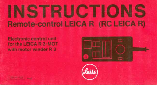
INSTRI,JCTIONS
                        LEICA R)Remote''control LEIGA R {RC

Electronic control unit
for the LEICA R 3-MOT
with motor winder R 3
View original page 1Page 2 · Read text
The RG LEICA electronic control unit      The RC LEICA R electronic control unit
increases the practical range of the        has an appliance cable of 2m length
LEICA R 3-MOT in many ways. The          with a screw plug.Extension cables
various actions and functions are ex-       (length 25m) with threaded coupling
plained in these instructions, which also    pfugs (Code No. 1 42741can be sup-
describe some practical possibilities.         plied. They can be combined into
More detailed information is contained     lengths of up to 100m for electric
in the working sheets for the LEICA        remote control. The RC LEICA R elec-
R 3-MOT').                                     tronic control unit is supplied with
                                            current by the motor winder R 3.


                                                                                       1) In preparation
View original page 2Page 4 · Read text
Brief description
        push-button1  Broad                                            ( =  ) for single-frame  and              release.       series
2 9mm high, two-digit red seten-segment dis-
  play of completed exposures. The segments
   light up for about 2 seconds after each ex-
  posure.
3 Reading key (r)for the display of the
  number of completed exposures at any time.
View original page 4Page 5 · Read text
After the key (3) has been dabbed, the digital   7 Slider switch for various functions:  display lights up for about 2 seconds.               Setting "LEICA" : camera is released
4 Input key (r) for the correction of the digital      through push-button (1) or interval switch (5).  display when a few exposures have already        Setting "TEST" :  release functions blocked.
  been completed without the RC LEICA R          Release intervals can be programmed by
  and the instrument has been switched off        means of the rotary switch (5). The release
  (only when the slider-switch is at "TEST").          impulse is signalled by the lighting-up of the
  Zeroing of the digital display through simul-        right-hand diode of the digital display (2), but
  taneous operation of the reading and input        the LEICA R 3-MOT is not triggered. This per-
  keys (r +r    ).                                   mits precise determination of the time inter-
5 Rotary interval switch with scale for auto-           vals. With switchover from "TEST" to "LEICA"
  matic single-frame releases at variable time        the camera is triggered at the preselected
   intervals.                                                    interval.
  Standby indication by LED of the digital dis-      I Screw Flugtl.
  play lighting up on the left.                     9 Explanation of function on the back of the
6 Slider switch for two interval ranges:The          instrument.
  switch "x1" or "x10" is digital and is therefore
   precise:
  Setting "x'1" :  about 1 frame/O.S sec.
  about 1 frame/1 min.                                                 1) suitable for same: 5-pin coupling plug, 302-013.1 54-004,  Setting "x10" :  about 1 frame/S sec.                Ernst Leitz Wetzlar GmbH, Technical Service Center,
                   'l frame/10 min.                                     P.O.8. 2027, D-6330 Wetzlar (Germany).  about                                                                                               5
View original page 5Page 6 · Read text
Connecting the instrument
                                         1. Set rotary interval switch (5) at "0".
                                     2. Unscrew the plug (8) in the socket of
                                     the motor winder R3 (match markings
                               on the plug and on the motor winder)
                                  and secure it by screwing it home.
                               The connection between the RC LEICA R
                                       electronic control unit and the motor win-
                                     der R 3 can be extended up to a distance of
                                100m.
                                                                DN:Date:cn=Mike2024.11.28signedButkus,by21:46:00Mikeo, ou=Butkus.org,Butkus-05'00'      email=mike@butkus.org, c=USMike Butkus                      Digitally


                               Manual release
                                         1. Set slider switch (7) at "LEICA" and
                                       switch on LEICA R 3-MOT.
                                     2. Brietly depress the broad push-button
                                               (1) for single-frame release.
View original page 6Page 7 · Read text
www.butkus.us


For series release continuously de-     The automatically determined or ma-
                                      (1).                                                  nually set                            As longpress      the         broad push-button
                                               "x"                                                          shutter:  1/90secspeeds(foras wellelectronicas the                                   an-       setting                                   after                 one frameas   this          is depressed
other is exposed; up to 2 frames per se-        flash synchronization) except "B" can be
cond depending qn the shutter speed.        used.
                                                                                      7
View original page 7Page 8 · Read text
Display of the completed exposure
After each exposure there is feed-back by
the camera. The number of the exposures
made with winder release appears as a
9mm-high two-digit red seven-segment
display (2), which lights up for about 2 sec.
after each exposure. At the position "36" of
the camera counter the motor winder and
the RC LEICA R are automatically switched
off, the digital display is erased.
Erase of the digital display through:
O switching off the camera with the main
   switch
o swinging out the film transport lever of
   the camera
   when the position "36" is reached on
   the film counter of the camera      o simultaneous operation of the reading
o  disconnection of the control unit from      and input keys (3 ahd 4) on the control
   the motor winder R 3                                unit.
I
View original page 8
Page 9 · Read text
Display of the completed exposures       Zeroing
    Through brief dabbing of the reading key   The digital display is zeroed by simul-
      (3) the number of completed exposures    taneous operation of the reading (3) and
     can be read at any time. The digital display     input keys (4).1
      tignts up for about 2 sec.


    l'

     Correctign of the digital display              lnterval releases
           lf a few exposures have been made without     Single-frame releases can beset at variable
 t   the RC LEICA R electronic control unit in    time intervals with the rotary interval switch I    position orthe display has been erased, the     (5) with scale. Because of the operating
                            R electronic    times between one exposure and the next, I     digital display of the RC LEICA                                                            below intervalsetting "5" in                                          with the     short timings - I    control unit can be made to agree                                                                are not possible at slow      film counter of the LEICA R3-MOT.           the "x1" range -
      1. Set the slider switch (7) at "TEST".          shutter speeds (from 1/15 sec.). The slider
     2. Dab the input key (4) until the desired    switch (6) serves for the choice of the         display appears.                               interval ranges "x1" and "x10".                                                                                               g
View original page 9Page 10 · Read text
Setting xl:  Interval range from about  Programming
0.5sec to about 60sec.                      1. Set slider switch (7) at "TEST". The RC
Setting x10: Interval range from about    LEICA R electronic control unit cannot
Ssec to about 600sec (:   10min). The     release the motor-winder R3 now. This
engraved scale values are orientating   prevents accidental releases when afilm
values (see graph). Precise times can be     has been inserted in the camera.
determined by means of a test (see next  2. Set the rotary interval switch (5) at the
sector "Programming").                  desired scale values.
                                               3. The left-hand diode of the digitaldisplay
                          4 +?:'ilHff ili'.T::.3?ffI  disita, dis-
                                                  play lights up when a release impulse  is
                                                       given. With the aid of this impulse check
                                         the desired interval can be timed, for
                                                  instance by comparison with the second
                                    hand of a watch. The rotary interval
                                               switch (5) is used for regulation.


10
View original page 10Page 11 · Read text
lmpulses can also be checked acoustically       watch. The rotary interval switch (5) is
when the LEICA R3-MOT is released. To      used for regulation.
avoid loss of a frame when a film is inserted     7. After regulation first set the sliderswitch
in the camera proceed as follows:                 (7) at "TEST" and zero the selector for
                                                   multiple exposures.
1 . Place the lens cap or camera body cover
   in position.                            With long intervals, the release frequency
2. Set the camera selector for multiple ex-    (impulse sequence) can first be regulated
   posures at "double exposure".               at 1/1 0 of the desired interval to save time.
3. Set slider switch (7) at "LE|CA",         By switching over from "x1" to "x10" the
4. Set the rotary interval switch (5) at the    desired long interval will be obtained.
   desired scale value.
5. The left-hand diode of the digital display
   indicates standby by lighting up.
6. The functional sequence of the camera
  makes the release impulse audible. With
   the aid of this impulse check the desired
   interval can be timed, for instance by
  comparison with the second hand of a
                                                                                                              11
View original page 11Page 12 · Read text
Example:                               Example:   Desired interval : 300sec (Smin).            Desired interval: 1 .3sec
                                              Set slider switch (7) at:'TEST"
Set slider switch (7) at "TEST".                     Slider switch (6) at "x10"
   Slider switch (6) at "x1"                     Turn the rotary interval switch (5)
  Turn the rotary interval switch (5)             roughly to scale value "4"
   roughly to scale value "7-8"                 Regulate impulse sequence at 13sec
   Optical impulse check                        with rotary switch (5)
   Regulate the impulse sequence via           Set the slider switch (6) at x1
   rotary switch to 30sec
   Set slider switch (6) at "x10"
Proceed analbgously  if you require very
accurate impulse intervals in the x1 range.

                                          Releasing the camera
                                      The LEICA R 3-MOT with motor winder R 3
                                                    is released when the slider switch (7) is
                                        changed from "TEST" to "LE|CA".
12
View original page 12Page 14 · Read text
Practical examples:                          Multiple exposures
     Self-timer                                              In conjunction with the selector of the LEI-
    The RC LEICA R electronic control unit can  CA R3-MOT for multiple exposures
    be used as a self-timer at variable delay   movement phases can be recorded on a
     times. The delay time is determined by the    single frame. As a rule the best results are
     setting of the interval, for instance scale    obtained in front of a dark background.\    value "$" :  about 1Osec delay time, when    Obviously, electronic flash units With stan-
     the slider switch (7) is set at "TEST". When    dard flash contacts (coaxial plugs) can be
     the right-hand decimal point of the digital    connected via the  f lash socket of the LEICA
     display (impulse check) lights up the slider   R 3-MOT. The shortest interval depends on
     switch (7) is set at "LE|CA".                  the recycling time of the flash unit used.
    The exposure will be made after about 10
     seconds. The completed exposure can be
    checked with the lighting-up of the digital
     display of the RC LEICA R electronic con-
      trol unit. After the completed exposure the
      slider switch (7) returns to "TEST".


     14
View original page 14Page 15 · Read text
Exposure control                           Tips for maintenance
lf the camera has been set up in conjunc-   The RC LEICA R electronic control unit is
tion with other accessories on a srte that is    maintenance-free. When used in very hu-
difficult to reach, the RC LEICA R electronic    mid surroundings or during rain it is best to
unit can be connected to check the ex-    protect the RC LEICA R electronic control
posures, for instance to the mains unit NL 3    unit by keeping it in a transparent plastic
in conjunction with the LS 16 lR light trap.    bag which does not obstruct the operation
Further practical examples, suitable con-     of the various controls.
necting layouts and circuit plans of the mo-
tor winder R3 and the RC LEICA R will be
found in thecollection of working sheetsfor
the LEICA R3-MOT1).


1) in preparation
                                                                                              15
View original page 15From the M. Butkus archive. Original publisher and archive notices are retained.
Check the model and edition against your equipment.
PDF verified 2026-10-10.