Film cameras
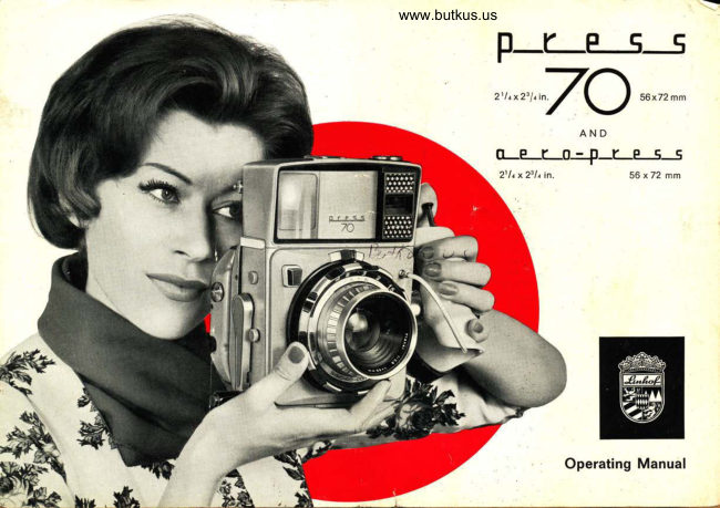
Linhof Press 70 / Aero-Press User manual
User manual for Linhof Press 70 / Aero-Press. 25 pages in English. Read the original PDF, download or print a copy without registration.
25 pagesEnglish3.2 MB PDF
Loading your manual…Open PDF directly
Document details
- Brand
- Linhof
- Model / document
- Linhof Press 70 / Aero-Press
- Document type
- User manual
- Language
- English
- Pages
- 25
- File size
- 3.2 MB
- Category
- Film cameras
- Document date
- Not specified in catalog
Search available document text
Find a term, then jump to its page in the original PDF. Image-only pages may not be searchable; check the PDF for exact wording and diagrams.
Page 4 · Read text
www.butkus.us


       We welcome you as the owner of a now LINHOF camera.
         You have purchased a valuable precision instrument which
             will increase your scop: in photography especia!ly  ii you
               har-rdle it in the proper rrvay. Please devot': your pariicular
               a'Liention to th: followinq instructions befor-c you start Ltsing
            vour camera.  lf you are in a hurry to acquaint youi-seli  vriilr
            the outflt, you will  fi nd sl-rort clcscriptioirs of tlr: operatioi-ts
              in the red fieids below thc v'arious illustrations.
          Your new camera rnras nr:ttiui'actured by, l-INHOF Precision-
           Camera-Works with great carc anci tficroughness   l'l possibl:l,
                     it should be protected front rain, sand and clusl. -[hrs rvill pa;'
             ofi by a long life and consiant i-eadincss oi'y'our camera
                  i\i'tcr long intensive use ii, is recon-rnrend;d that you retLti-n
               )'our camera to the factory or to your nearest LINHOF se,'-
                   ',,ice laiorkshop for a general checkup.
ci        Thetlrc AE[]OfollowingPniSS!nstructionsSpecialareinstrirctionsto a largepertainingextent alsoto thevalidope-fc;r
ut$*,         ration of the AERO PRESS. which are d,{ferent from tire
             l-'RESS 70, are contained on page 1B**21 of this bocl<let


            Please make sure that you obtain the camera "passport" with
            your camera.
           The guarantee registration card attached to it should be filled
               in and mailed to us so that your guarantee becomes effective.
          Upon recelpt of the registration card you will also recelve a
            complimentary sample copy of the leading quaterly magazine
          INTERNATIONAL PHOTO-TEC!'|N|lK (Groftbild-Technik) and,
            from time to time, information material from our Gustomer
           Service Department.
View original page 4Page 6 · Read text
www.butkus.us


    Operating Parts and Components:

  1. Accessory shoe for additional finder or flashgun                    16. Anatomical Grip
  2. Front lens of range-viewfinder                                      17. Flash synchronization selector
  3. SUPER ROLLEX back for ten exposures 21/ax23/a in.             18. Lug for carrying strap
    (56x 72 mm) on 120 rollfilm                                              19. Selector knob for telephoto delineation
 4. Stop for film transport lever 7                                     20. Automatic distance indicator
  5. Body shutter release button                                       21. Clip for film identification (flap of film package)
  6. Automatic exposure counter of SUPER ROLLEX                   22. Eyepiece of range-viewfinder
  7. Rapid crank lever for film transport and shutter cocking         23. Automatic locking slides of SUPER ROLLEX
                                                                                                                                                                                                                                                                                                                                                                                                                                                                          '  8. Locking lever for SUPER ROLLEX back                            24. SUPER ROLLEX BACK for ten exposures 2t/ox2s/4in.
 9. Release button for fold-away handle                          (56x72 mm) on 120 rollfilm
10. Exposure meter scale                                              25. CINE ROLLEX BACK for up to 53 exposures 2t/ax23/ain.
11. Built-in photo-electric exposure meter                                (56 x 72 mm) on perforated 70 mm film
12. Cable release inserted into Anatomical Grip                      26. Automatic frame counter of CINE ROLLEX
13. Release button for lens-change                                       27. Control window for film transport
14. Lens setting ring with distance scale (feet or meters)             28. Readiness indicator (redlgreen)
15. Setting ring for diaphragm and shutter speed
                                     Technical specifications subject to change without notice.
View original page 6Page 7 · Read text
F'


             Aiming of the Camera
                      Vertical Gomposition
                The PRESS 70 is always ready for use. Unlike a press-type camera fitted with a drop bed, it need not be
                 opened and set for infinity. The left hand reaches from behind under the leather strap of the Anatomical
                      Grip. The fingers grasp the Anatomical Grip almost automatically and the thumb rests on the cable release
                    plunger (12). The right hand supports the camera body from below, the camera resting in the palm of the
                   hand. In this position, thumb and index finger can operate the knurled focusing ring (14) in a convenient
                   manner. The left eye looks straight into the eyepiece (22) and will recognize luminous vertical format image
                       delineations.

                      Horizontal Composition
                               lf the photographer decides on a horizontal composition, the whole camera is turned 9Oo in such a way
                     that the left hand, which holds the camera by its Anatomical Grip, is on top. Because the camera back
                   cannot be rotated, the negative is in the correct position coinciding with the format delineation of the finder.
                The right hand also supports the camera from below and helps to carry the weight of the equipment. Com-
                       fortable holding of the camera is further facilitated  if the crank of the lever (7) for film transport and shutter
                    cocking has been folded away by pressing on the button (9). The shutter may be released conveniently by
                    pressing with the thumb on the push button body release (5).

                  The Gamera Readines
                         is indicated by "green" in the control window (28). By operating the film transport lever (7) to the stop and
                       returning  it until  it clicks in its basic position, the film is transported one frame and the shutter cocked at the
                same time. lf this operation has not been carried out before the exposure, a red signal appears in the
                       control window. A safety device prevents releasing the shutter unless the dark slide is pulled.
View original page 7Page 9 · Read text
Sirarpness  arrct Corrposition
In hand-held photography the lens is most conveniently focused with the rangefinder. The superimposed
rangefinder image may at first show double contours, specially noticeable on conspicuous vertical lines (see
above left), which must be brought in line by turning the knurled focusing ring (14) (see above right). Please
make sure to focus the iens on the most important parts in the centre of the picture on which the plane of
critical sharpness should rest. The distance focused on is at the same time indicated on the automatic
distance scale (20). Focusing can also be carried out on the groundglass  if you work from a tripod. For that
purpose the accessory groundglass back is used which, besides the 56 x72 mm format, also indicates the
2t/0x31/r in. format  if you intend to work with double cutfilm holders.
The image areas for three focal lenghts are shown within the luminous frame lines in the viewfinder lndi-
cating the 56 x72 mm format  (ill. 3 and 4). The outer lines indicate the field for 53 mm wide angle lenses;
the middle lines frame the image area of B0 mm normal lenses; the smallest frame shows the field for
180 mm telephoto lenses. When you are not using the 180 mm lens, turn the button (19) to swltch off the
luminous telephoto frame in the viewfinder so that you have an unobstructed view of the normal and wide
angle frames. (ill.4). The finder image areas are automatically corrected for parallax and for reduction-of-
field down to a focusing distance of 47 in. with wide angle and normal lenses and down to 6r/z feet with
180 mm lenses. When you focus on still closer subjects, red signals appear in the luminous frame lines
to remind you that the automatic compensating mechanism has passed its closest limits, and that you must
make any additional correction yourself.  (ill. 4). The level indicator visible near the top edge of the finder
image is an important aid in avoiding converging lines when using wide angle lenses; the two pointers of
the indicator match when the optical axis of the lens is perfectly level or, in other words, when the film
plane is perfectly vertical.
View original page 9
Page 11 · Read text
Exposure Meter
                 The built-in exposure meter of your PRESS 70 will provide
                  you with correct exposure information for the great majority                                                                                                                          $i
                       of your work so that, under normal conditions, you need not                                                                                                                                                                                      fl:
                        carry a separate meter. The operation is quite simple:                                                                                                                                                                                                                                ;'
                             First, rotate the inner disc of the meter until the notch is opposite the film speed used. Point the camera                                                            i;
                     towards the subject and turn the grooved outer ring of the meter to match the red pointer with the needle.
                  The meter scale will give you the exposure time for any desired f-stop. For incident light measurement
                     from the subject towards the planned camera position    slide the diffuser over the honeycombs of the meter.-                                                                                    -
                       Shutter Speed and Diaphragrn
                  The diaphragm and shutter speed values indicated by the exposure meter are transferred to the adjusting
                          ring on the lens mount. Please note that there is only one clearly visible red index mark on the lens mount                                                   fI                        for distance scale, diaphragm scale and shutter speed scale. First, set the desired shutter speed by turning
                   on the outer milled ring. Then adjust the diaphragm scale by turning on the black protuding cam. The two
                        pointers to the left and right are the index marks indicating the depth-of-field.  lf the depth-of-field indicatecj
                   by the pointers is not sufficient  it can be increased by turning on the outer milled ring or, in other words,
                  by changing the shutter speed. While the indicators move apart increasing the depth-of-field (by closing
                      the iris diaphragm) the shutter speed is increased proportionately. By turning the shutter speed ring in the
                     opposite direction the depth-of-field indicators move closer together while at the same time the iris
                    diaphragm is opened and the shutter speed shortened. Caution: When the final position of the indicators
                            is reached, automatic adjustment of the diaphragm stops!

                     Lens Change
                     Lenses can only be changed after cocking the shutter by means of the transport lever (7). First make sure
                       to insert dark slide. Then push the release on top of the lens mount (13) in the direction of the arrow, while
                         at the same time pressing with the tip of the thumb on the black plate below. Now the lens can be removed
                   by pulling it out straight forward. When inserting another lens make sure that the red index is on top, oppo-
                           site a square index on the camera body above the lens mount.     ntn
10
View original page 11Page 13 · Read text
Loading of SUPER ROLLEX Back
                 Open SUPER ROLLEX by pressing both locking slides (23) together. The lid snaps open by spring pressure.
                  Remove film carrier (ill.7A). Insert unexposed film spool as shown in ill. 7B and C so that the black
                      side of the paper leader is on the outside when pulled around the face of the insert. Thread leader in
                     the slot of the empty film spool and advance by operating the small auxiliary lever  (ill. 7C) in the circle)
                           until the arrow or triangle appears in the alignment window (ill. 7C). Insert film carrier into the SUpER
                 ROLLEX body so that the film counter is at the right side. Close cover and advance film with the crank (7)
                           until it stops automatically showing the number 1 in the frame counter window (6). (About three full swings
                       of the transport lever are required.) Make sure to remove the dark slide before releasing the shutter (film
                        transport and shutter cocking are coupled, but shutter can only be released after removing dark slide).
                      Transport film after each exposure by operating the lever (7) as described above. After the ioth e"posrre
                     about three more swings of the transport lever (releasing the shutter after each lever swing) are required to
                    wind up the paper trailer. Thereupon the SUPER ROLLEX back can be opened to remove the exoosed film

                      Loading of CINE ROLLEX Back
                  Remove CINE ROLLEX after operating the quick change lever (8) and fold out the cog wheel (ill. 8 A     ifr"
                               left circle). Turn the locking disk (ill. 8 A in the right circle) and remove film carrier. Remove empty cartridge'n
                    from the film carrier. Remove cap of cartridge and take out the film reel. Feed leading edge of film from
                 a loaded cartridge into the slit of the empty film reel in such a way that the two cams engage in the per-
                          foration. The emulsion must face the reel. Insert the reel with film attached in the cartridge and close cap.
                 Open the retaining spring of the film carrier (ill. 8B).
                        Insert the cartridges into the film carrier as shown by the guiding lines on the inner wall of the film
                                       (ill. BB). Insert the cartridges into the film carrier as shown by the guiding lines on the inner wall of the film
                          carrier  (ill. BB). Close retaining spring and clamp film to pressure plate as shown in ill.8C. Push film car-
                          rier into the CINE HOLLEX body, making sure that the cog wheel is folded out and close with the locking
                         disk. After making three blind exposures number 1 will appear in the frame counter window. The camera is
                 now ready for operation.


12
View original page 13Page 15 · Read text
The Quick-change Camera Back
The PHESS 70 is fitted with the exclusive LINHOF quick-change back wich permits instant changeover from
black-and-white to color, from rollfilm to sheetfilm whenever necessary or desirable. To operate the quick-
change mechanism, simple turn the quick-change release (B) in the direction of the arrow. The following
camera backs are available: 1. SUPER ROLLEX back for ten exposures 2t/ax2s/a in. (56x72 mm) on 120
rollfilm. (Standard equipment with PRESS 70.) Composition and focusing by range-viewfinder or ground-
glass. 2. CINE ROLLEX back for up to 53 exposures 21/ax2s/a in. (56x72 mm) on perforated 70 mm film.
(Standard equipment with AERO PRESS). Composition and focusing by range-viewfinder or groundglass.
3. Universal groundglass springback. Serves for composition and focusing on the groundglass; the formats
2t/o x31/r in. or 6.5 x 9 cm for single exposures on cutfilm or plates and 21/a r23/o in. or 56 x 72 mm rollfilm
or 70 mm perforated film are indicated. The UNIVERSAL BACK serves to hold double cut film and plate
holders by means of its spring-back feature. All backs are attached to the camera in vertical format position
so that the red triangle marks visible on the right side of the film backs and the back frame, match (ill. 9)
and the cog wheel, which partly protrudes from the film back, engages the corresponding groove on the
back frame

Using Doubte Holders
For taking individual exposures on cutfilm or plates, remove the rollfilm back by means of the above de-
 scribed quick-change lever and attach the groundglass spring back as shown in ill. 10 so that double holders
can easily be inserted from below. LINHOF combination sheet film/plate holders 2t/ox31/t in. or 6.5x9 cm
LINHOF Super cutfilm holders as well as other standard 2t1ox3t/t in. double holders or fllmpack adap-
ters may be used interchangeably. Double holders are inserted between groundglass frame and camera
body until they click positively in position. The spring-loaded groundglass frame holds the double holders
in the focal plane. For removal the double holders are slightly lifted backwards and pulled out.
View original page 15
Page 17 · Read text
Accessories for PRESS 70
 1. Optical Equipment:                                             4. LINHOF combined cutfilm/plate holder 2t/ox31/t in.
   Carl Zeiss set: Press Planar      80 mm f/2.8            5. Ekalite Field Lens
                 Press Biogon      53 mm f/4.5            6. SUPER ROLLEX back for 10 exposures 21/tx2s/4 in.
                 Press Sonnar     180 mm f/4.5             (56x72 mm) on 120 rollfilm
   Schneider set: Press Xenator     B0 mm f/2.8             7. CINE ROLLEX back for up to 53 exposures 2t/a x2t/a in.
                 Press Super Angulon 53 mm f/4                  (56 x 72 mm) on perforated 70 mm film
                 Press Tele Arton   180 mm f/4                                                                 8. Slip-in filter for use in LINHOF lens shade / flter holder
   All lenses are mounted in special Synchro Compur shut-                                                                     9. B x focusing magnifier for critical groundglass   ters with coupled click-stop diaphragm/speed  setting and                     r/soo                                                  observation  speeds up to      sec.
                                                                10. LINHOF lens shade /flter holder   In preparation: Rodenstock Rotelar 270 mm f/S.6                                                                                                      1 l. Camera back for groundglass observation and use2. Super cutfilm holder 6.5 x 9 cm                                                                       of cutfilm holders.
3. LINHOF combined cutfilm/plate holder 6.5 x 9 cm
View original page 17Page 20 · Read text
www.butkus.us


                      Trarrsporting Filrn end Cocking the Shutter
              On the AERO PRESS, these two operations are
                   also coupled automatically so that unintended
                double exposures are safely prevented. By
                    turning the reight-hand Anatomical Grip to a
                   stop and returning it to its starting position (as
                shown in the  ill. on page 20 and 21) the film is
                   transported and the shutter cocked simultane-
                      ously. ln order to prevent an unintentional opera-
                       llon of the right-hand Anatomical Grip, it is locked
                  by the push button (2) so that the operation can
      ti             only be carried out after pressing on this but-
\ %           ton.releasedThe beforeright-handeachAnatomicaloPeration.  Grip must be
              The operation of the Anatomical Grip which
                 cocks the shutter is also required prior to a
                   lens change because the release slide (7) for
                   removing the lens can only be moved when the
                     shutter is cocked. ln order to prevent the pho-
                   tographer from forgetting to pull out the dark
                      slide of the CINE ROLLEX, the shutter can only
                bc released after its removal.
View original page 20Page 24 · Read text
www.butkus.us


            Open Frame Finder

                 Unlike the PRESS 70 the AERO PRESS does
                 not have an optical range-viewfinder but a large
              open frame finder (page 1B) which is specially
               adapted to the rugged use in aerial photo-
",h_             graphy. The finder shows two delineations, on
 " -j            the right half for 180 mm and on the left half                for B0 mm lenses. As with other open frame
                   finders, paraliax compensation has been omitted
              because the camera is primarily intended for
               use at infinity in aerial photography. For framing
                the subject, the frame finder is held in front of
                 the eye in such a way that the larger front frame
             and the smaller back frame coincide. The ca-
              mera is most conveniently held by its two Ana-
               tomcal Grips without the necessity to press the
              head against the back of the camera. The fin-
             der delineation indicates the 21/tx23/+  in.
                  (56 x 72 mm) format for vertical composition.
                 In the case of shooting horizontal format the
               whole camera must be turned 90o.


                                                                                   21

                                                     4h{
View original page 24Related documents and language editions
From the M. Butkus archive. Original publisher and archive notices are retained.
Check the model and edition against your equipment.
PDF verified 2026-10-10.