Lenses & filters
Linhof Super Technika V adjustment instructions for wide angle lenses User manual
User manual for Linhof Super Technika V adjustment instructions for wide angle lenses. 7 pages in English. Read the original PDF, download or print a copy without registration.
7 pagesEnglish3.1 MB PDF
Loading your manual…Open PDF directly
Document details
- Brand
- Linhof
- Model / document
- Linhof Super Technika V adjustment instructions for wide angle lenses
- Document type
- User manual
- Language
- English
- Pages
- 7
- File size
- 3.1 MB
- Category
- Lenses & filters
- Document date
- Not specified in catalog
Search available document text
Find a term, then jump to its page in the original PDF. Image-only pages may not be searchable; check the PDF for exact wording and diagrams.
Page 1 · Read text
www.butkus.us


       --m


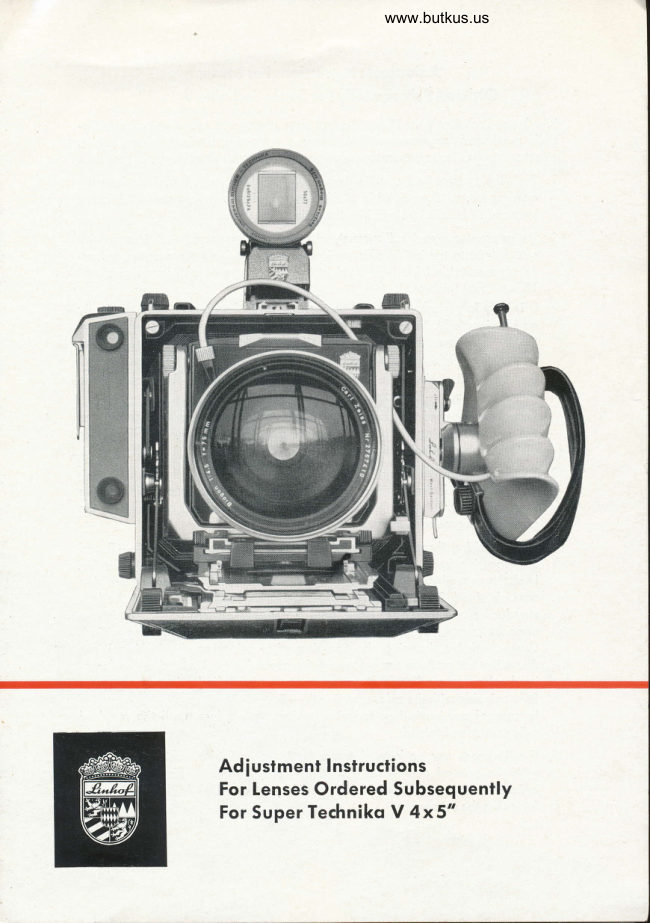
Adlustment lnstructions
For lenses Ordered Subsequently
For Super Technikq V 4x5"
View original page 1Page 2 · Read text
Adiustment Instructions For Lenses
        Ordered Subsequently For Super Technikq V 4x5"
 The SuperTechnikoY 4x5" for the first time permits fo selfodiust oll odditio-
  nolly purchosed rongefinder-coupled lenses. Following the instructions below,
  exoct correspondence between rongefinder ond ground gloss imoge is obtoined.
  l.  Push the premotched coupling com supplied with eoch lens fully into the
   com mount, until on oudible click is noticed. Pull out lens stondord, insert
     lens ond slide infinity stops inio the roils of the upper trock.
 2. To guorontee exoct odiustment, ottoch the tronsporent test imoge with
     scotch tope to the inside of o verticol window. Position the comero, mount-
    ed on o suitoble fripod, porollel to the test imoge of o distonce of obout
     l5 feet (5 m) (picture'l).
,      lt is very importont to exocily center ond level the comero both verticolly
    ond horizontolly. To focilitote this operotion the use of o Linhof spirit level
    (ZYW) is recommended. When looking stroight through the rongefinder
     oculor, the height odiustment of the comero should be mode in such o woy
     thot the smoll circle of the rongefinder imoge oppeors in the center of the
     reference line A-  B (picture 2).
     Exoct olignment of the comero in relotion to the test imoge is essentiol for
    the entire focusing ronge, it becomes most criticol, however, for close
    distonce focusing below 5 feet.
 3. To evoluote criticol shorpness on the ground gloss, o good opticol mogni-
     fier (Linhof opticol mognifier, 8 x, ZYL) must be used. Before beginning the
     finol odiustment, the mognifier oculor should be focused criticolly on the
    groin of the ground gloss.
 4. When looking through the rongefinder oculor, oim ot the line A  B ond                                                                      -     turn focusing knob until this line is perfectly focused in the ronge finder.
    Lock the extension releqse to prevent on olterotion of the focusing position
   now obtoined. Press the spring-tensioned grips slightly ond move the lens
    stondord olong the upper trock, until the squore pottern of the test imoge
    qppeors completely shorp on the ground gloss (use opiicol mognifier).
    Cross-check by chonging the focusing ofter releosing the locking lever.
    Focus the test poitern once more on the ground gloss by turning the focus-
    ing knob. lf lens odiustment wos correct, the rongefinder imoge must now
     fully coincide with the reference line A     B.                                          -     ln cose of ony deviotion, repeot the obove procedure, uniil the required
    odiustment is obtoined.
 5. lf odiustment wos performed correctly, the rongefinder must now coincide
    with the ground gloss over the entire focusing ronge. Finolly, push the
     infinity stops ogoinst the lens stondord mount ond Jock in this position by
    fostening the set screws.
View original page 2Page 5 · Read text
Digitally signed by Mike ButkusMike                 DN: cn=Mike Butkus, o=Butkus
                             camera manuals, ou=butkus.org,
                                email=mike@butkus.org, c=US
                                  Date: 2020.10.12 22:49:46 -04'00'Butkus


        Mounting of Additionol Infinity Stops between olreody
        Adiusted Stops.
                   lf odditionol infinity stops hove lo be mounted between olreody provided stops
          proceed os follows:
          'L Remove on one side (1 )one of ihe olreody provided poir of infinity siops
             which prevent oddiiionol lenses to be mounted. To do lhis, loosen sei screws
           ond push the stop from the roil.
          2. Adiust new infinity stop os described before ond lock ii by refostening the
                set screws.
         3. Pull up ihe second remoining slop shown in red colour on picture (2) ond
             push Iens stondord fully ogoinst  ii.
          4. Slide infinity stop removed occording to l. bock on the comero roil until  it
              touches the lens slondord. Re-fosten set screws.
         5. Proceed in exoctly the some monner on the opposite roil with the remoining
                  infinity siop.
                  lf the olreody mounted stop is positioned ioo close io the new infinity stop so
            thoi on exoct olignment is not possible, speciol infinity stops con be delivered.
        When ordering new lenses it is recommended to stqte which lenses ore olreody
          coupled to the comero.
View original page 5Page 6 · Read text
www.butkus.us


Mounling of Distqnce Scole on the Scole Stoge
1 Remove scole sioge (see ill. 2).
2. Push new distonce scole into ihe open end of the scole stoge ofter removing
   the screw (poge 1, ill. 3). Do not lock.
3. Push scole sioge on scole mount. Scole stoge must be properly engoged.
4. Move distonce scole on scole sioge until the index pointer on the upper
   irock coincides exocily with the infinity mork of lhe distonce scole. li  is
    essentiol ihoi the comero trock is in zero position.
5. Remove scole stoge corefully ond lock ihe odiusted distonce scole on its
   bottom by fostening ihe screw (1).
6. Re-inserf scole stoge.
lf on olreody odiusied dislqnce scole prevents the exoct odiustment of o new
scole, remove the old scole ofter loosening the locking pin. Re-insert ofter
odiusting the new scqle. Full coincidence with the second index pointer on
infinity is required. lf it is not possible to odiust the new scole opposife one of
the two index pointers, o new scole stoge is required.
Scqles or Distqnce Scqles for Wide-Angle Lenses f :  90 ond
f:75mm
Adiust ihese scoles os described qbove but push upper trock in wide-ongle
posiiion until it clicks oudibly. (ill.4 ond insiruction monuol of Super Techniko
V4x5  in.).


                                               \
View original page 6Page 7 · Read text
Use of Wide-Angle Lenses f :  90 qnd f :  75 mm
     When using the rongefinder with the qbove wide-ongle lenses, olwoys push
      upper trock bqck to wide-ongle position. Wiih the Super Techniko V, comero
       drop-bed ond lens stondord remoin in normol position (90o to comero body);
       ihe comero bock hos 1o be in horizontol position. For veriicol pictures turn
      comero 90o.


 www.butkus.us


NIKOTAUS KARPF KG. . PRAZISIONS-KAMERA-WERKE   . MUNICH 25
Printed in Germony 640414e                                                Technicol spezificoiions subiect lo chonge
View original page 7Related documents and language editions

From the M. Butkus archive. Original publisher and archive notices are retained.
Check the model and edition against your equipment.
PDF verified 2026-10-10.