Film cameras
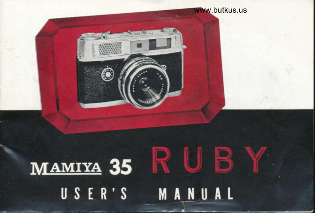
Mamiya 35 Ruby User manual
User manual for Mamiya 35 Ruby. 21 pages in English. Read the original PDF, download or print a copy without registration.
21 pagesEnglish4.0 MB PDF
Loading your manual…Open PDF directly
Document details
- Brand
- Mamiya
- Model / document
- Mamiya 35 Ruby
- Document type
- User manual
- Language
- English
- Pages
- 21
- File size
- 4.0 MB
- Category
- Film cameras
- Document date
- Not specified in catalog
Search available document text
Find a term, then jump to its page in the original PDF. Image-only pages may not be searchable; check the PDF for exact wording and diagrams.
Page 2 · Read text
NOMENCTATURE


Mike Butkus                 Digitally                                                          DN:email=mike@butkus.org,Date:cn=Mike2024.05.31signedButkus,by21:41:51Mikeo=ButkusButkusc=US-04'00'camera manuals, ou=butkus.org,


       1. Cocking Lever                     8. Cartridge Chamber
      2. Shutter Button                    9. Viewfinder Window
       3. Rewind Crank                   10. Eyepiece
      4. Focusing Flange                  11. Exposure Counter
      5. Backlid Catch                    12. Aperture Dial
      6. Take-Up Spool                   13. Shutterspeed Dial
       7. Sprocket                        14. Selftimer Lever
View original page 2Page 3 · Read text
www.butkus.us
15. Synchroflash Socket                   2r.  Filmspeed Dial
16. Synchroflash Adjustment              22.  Meter Needle
L7. Distance Scale                         23.  Guide Lines
18. Depth of Field Scale                   24.  Cross-Coupling Needle
19. Rewind Button                       25.  Zero Point
20. Rewind Indication                     26.  Accessory Clip
                                                 27.  Strap Eyelets
                                               28.  Tripod Socket
                                               29.  Focal Plane Mark
View original page 3Page 4 · Read text
Bitte spenden Sie 2,50 Euro, um diese Website über E-Bay zu unterstützen ... www.PayPal.me/butkusView original page 4
Page 5 · Read text
GENERAT DESCRIPTION
  cAUTloN: Read these instructions carefully for a thorough understanding
of the functions of this camera before trying out the actions of the cockinglever (1), dials, and controls.
  cRoss-couPtED ExposuRE ilETER The MAMIyA 35 RUBY has a buitt-in
wide'range exposure meter which permits an extremely broad range of light-
                                     intensity measurement and exposure
                                       control without shift of scale. Simple,
                                       botherfree operation is possible with all
                                types of subjects, from bright snow
                                    scenes and beach shots down to darkly
                                                            lit  interiors where full aperture and
                                     slowest shutterspeed must be used even
                                  with high speed (ASA 100 and up) film.
                          To use built-in exposure meter for
                                  automatic exposure control.
                                  1)  First set the filmspeed dial (21) to
                                      the ASA rating of the film in use. Unless
                                        this is done, the cross-coupling of the
                            meter indication with the exposure
View original page 5Page 6 · Read text
www.butkus.us
controls (shutterspeed and aperture dials) will be out of step.
  2) Train camera on the subject, making sure that the photocell is not
obstructed. The meter needle (22) will immediately indicate the brightness
of the subject-matter.
  3) Adjust either the shutterspeed dial (13) or the aperrure dial (12) to
move the cross'coupling needle (24) into alignment with the guide line in-
dicated by the meter needle (22). When this is accomplished, the controls
are set for correct exposure of the film.
  GoGKlNc tEvER AcrtoN Hook thumb on tip of cocking lever (1) and push
counter-clQckwise through an arc of about 180 degrees until the stroke
comes to an end. This action will advance the film by one frame, and will
cock the shutter mechanism. The lever will spring back to its original
position upon release. However,  it  is preferable to ease it back without
removing the thumb.
  couPtED RANGEFINDER When the focusing flange (a) is moved by means
of lingertip action, the lens moves in and out on its mount. This move-
ment is coupled to the rangefinder, so when the subject is sighted through
the eyepiece (10) the superimposed images visible in the small center focus-
ing spot can be made to coincide. When accurate merging of the images
is effected, the subject is in correct focus, and a sharp picture can be
obtained.
View original page 6
Page 8 · Read text
www.butkus.us
so that its spindle does not protrude into cartridge
chamber (8) (Fig. 1).
  2. Place safety cartridge containing unexposed film
in cartridge chamber (8), seeing that it  fits snugly in
the right direction. Press down rewind crank (3)
so that spindle engages the cartridge and holds it
in place. If spindle does not engage properly, turn
slightly. Next, pull out about four inches of  film,
and fold inward (toward the dull emulsion side)
about a quarter inch of the end (Fig. 2).
  3. Insert folded end in the slit of take-up spool (6),
which can be brought into convenient position by
turning spool in either direction by thumb tip. With
end of film caught in the slit, turn spool so that
sprocket (7) also rotates, and wind at least one turn
of film onto spool, seeing that the perforations on
the lower side of the film engage the sprocket teeth
(Fig. 3).
  4. Holding film taut and in position, check safety
cartridge, then turn rewind crank 13) clockwise, as
indicated, to take up all slack (Fig.   ).
View original page 8
Page 9 · Read text
5. With slack gone, turn take-up spool (6) slightly with thumb to see that
film and sprocket (7) are properly engaged, and that the rewind crank (3)
turns counterclockwise with the film feeding smoothly out of the safety
cartridge. Close backlid, which will catch when pressed down.  If, when
closing backlid, the perforations on both sides of the film are caught on
the sprocket the full number of exposures may not be available because too
much film has been wound onto the take-up sprocket.
  6. Turning the milled flange around the hub of the cocking lever (l),
set the exposure counter (11) so that it indicates " S "  (start).
  7. Preferably keeping the lens covered, operate cocking lever (1) and
shutter button (2) three times until numeral 1 is indicated by the exposure
counter (11 . The camera is now ready for the first picture.
  8. When, during cocking action, the film is being taken up properly, the
rewind crank (3) will turn counterclockwise (against the arrow indication).
If there is no motion, rewind film, taking care that end is not wound into
the safety cartridge ; open backlid, and repeat loading procedure. Do not
turn rewind crank (3) counterclockwise while picture-taking.
  9. After loading, always turn filmspeed dial t21) to correct ASA setting.
                    CAMERA GRIP
 Any comfortable grip affording good steadiness will do, provided the
View original page 9Page 10 · Read text
www.butkus.us
fingers do not obstruct the viewfinder or disturb the exposure controls.
  Ilorizontal Position Grip camera from the sides with both hands. The
left index finger operates the focusing flange (4). The right thumb is
hooked lightly on the cocking lever (1), while the right index finger is
curled over the hub of the cocking lever so that  its tip rests lightly on
the shutter button (2). Bring the camera up to eye-level, and sight with
right €y€, keeping the left eye lightly closed. Maximum steadiness of
obtained by keeping the elbows close to the body (Cut A).
  Yertical Position Two alternative grips are possible.
  1. Grip as for horizontal position, then
turn top of camera to the left. Change left
hand grip so that camera is held squarely
in the palm which is pressed against the
cheek. The right hand steadies the camera
from above. If focusing must be adjusted,
use left index finger (Cut B).
  2. Turn top of camera to the right, and
grip with right hand from below. Use
thumb, in this case, to operate shutter
button. Right index finger can be used for
focusing.
View original page 10
Page 11 · Read text
When using either of these vertical positions, fine
                          focusing can be done more easily by first focusing
                            in the horizontal position.
                           FOCUSING
                    When using the coupled rangefinder to fccus the
                       camera, sight through the eyepiece, and position
                          the main subject within the focusing spot at center
                          of the field.   Correct positioning is  particularly
                          important when photographing at close range.
                       For ease of judging merging of images in the
                        focusing spot, select verticals, such as window
                        frames, poles, tree trunks, cheek and nose lines.
                         Highlights, such as are given off by  eyeglass
                           frames, also permit easy focusing.
                    The bright translucent frame seen in the view-
                          finder field indicates the limits of  the  finished
                         picture (at infinity and long ranges). When close-
                      range pictures are taken, parallax must be con-
                           sidered. Allow for the shift of the entire frame
                    by using the right-angle mark inside the upper

www.butkus.us
View original page 11Page 12 · Read text
www.butkus.us
        left corner of  the
      main border frame.
       When correct focus
     has been obtained,
       the distance from the
     camera (focal plane
     mark (29)) to the sub-
       ject is indicated by
       the distance scale. The color-coded depth of field scale that lies adjacent
N      to the distance scale 117) gives the amount of focusing tolerance available,
       depending on the aperture setting (match color with the numerals on the
       aperture scale).I        Depth of field is the permissible divergence from exact focus, which still
      gives sharp reproduction of the subject. The smaller the aperture, the
       greater the tolerance.
                      EXPOSURE DETERMINATION
        1. Check filmspeed dial (21) to see that it is set at the ASA rating of
       the film in use.
        2. Train camera on subject. Meter needle (221 will move. Turn either
       the shutterspeed dial (13) or the aperture dial (12) (both if necessary) to
View original page 12Page 14 · Read text
www.butkus.us
bring the cross-coupling needle (24) into alignment with the meter needle
(22) through one of the guide lines (23). The controls are then set for
correct exposure.
  3. Either the shutterspeed dial (13) or the aperture dial (12) can be
preset at the desired setting before adjusting the cross'coupling needle (24).
However, in the case of the shutterspeed dial (13) the setting must be
exactly at the click-stops: intermediate positions cannot be used. The
apertrrre control is continuous, so any position on the scale will give the
corresponding aperture size.
  4.  If, with the photocell window completely covered, the meter needle
(22) does not indicate zero point (25), remove screw plug and adjust by
moving lever inside the top casing.
 When photographing people To obtain the proper light value (bright-
ness) of the subject, the best way is to move up close enough so that only
the light reflected by the subject itself excites the phctocell and light
meter. It is usually best to exclude the light from the background, skY,
foreground and reflections.
 When taking pictures of human subjects, measure reflected light from a
distance of about four or five inches, using the mean'  if  desired, of the
highlights and shadows. When measuring brightness at close range avoid
casting a shadow on the subject.
View original page 14
Page 15 · Read text
Scenery When, in photographing scenery or making snapshots,  it   is
difficult to get close to the main subject-matter, point the camera toward
the foreground a few feet away from camera position in order to avoid
overexcitation of the photocell by strong light from the sky. When photo-
graphing wide vistas or distant peaks, reduce aperture setting by one
step, or increase shutterspeed by a step. For example,  if the cross-coupl-
ing needle (2a) is in alignment with the meter needle (22) when aperture
is fill  and shutterspeed is at 11250, then either increase shutterspeed to
1/500 or reduce aperture to f/16.
  Under reyerse lighting conditions
  1. Silhouette effect can be obtained, when light is coming from behind
the subject, if when determining the exposure control settings the bright-
ness of the background, not the subject itself, is measured.
  2. To obtain a good reproduction of the subject, disregard the background
and measure the reflected light coming from the subject only by measur'
ing at close range.
  3. To obtain a good reproduetion of both the subject snd the background
use the mean of the settings obtained for the subject and background
separately.
  USE OF FILTERS Because filters are effective by virtue of their ability to
absorb some of the light they transmit,  it  is necessary to compensate for
View original page 15
Page 16 · Read text
www.butkus.us
       thrs loss when filters are used. The absorption factor of each filter  is
       indicated by numerals expressing the amount by which exposure must be
       increased-e. g. X1.5; x2;  x/, & c.  With the MAMIYA 35 RUBY com-
       pensation is simply effected by adjustment of the filmspeed dial (21). For
      example, if the film in use is ASA 200, and the filter  rrsed has a factor of
       x2, simply change the setting of the filmspeed dial (21) to ASA 100; if the
       factor is X4, change setting to ASA 50.
                       UNLOADTNG FIIM?
   I      When the specified number of exposures per roll of film (20 or 36) have
      been made, stop p:cttrre-taking. Do not attempt to sqeeze in one more
      frame. Return exposed film into safety cartridge for removal frcm camera.
 1        1. Push rewind button (19), it should remain depressed. Erect rewind
      crank (3) and turn clockwise, as indicated, to wind film into safety cart'
        ridge.
        2. When all of the exposed film is rewound into the cartridge, and the
      end is detached from the take-up spool (6), this can be felt by a stiffening
      and easing of tension. However, if  it is desired not to wind the end into
      the cartridge, watch the rewind indication (20), and stop rewinding when
      the rewind button ceases to turn. Open backlid, pull out the rewind
      crank, and remove safety cartridge from the camera. The depressed
View original page 16Page 17 · Read text
rewind button (19) will automatically return to original position when the
cocking lever (1) is next operated.
  Caution  l. When more than the specified number of exposures  is attempt-
ed, and in some cases before the full number of frames have been exposed,
the film may come to an end to cause the cocking lever (1) to jam par[
way through its stroke. In such cases never force the lever. Press the
rewind button (19) and operate cocking lever while keeping the button
depressed. Cocking lever will complete its stroke and return to original
position.
  caution 2.  If force is applied to the cocking lever (1) when it  is held
by the film coming to an end, the film                                     -uv  become detached from thespool in the safety magazine, making it  irnpossible to rewind the exposed
film into the magazine. In such case, if film is to be saved, open camera
in a photographic darkroom, remove film and replace in safety cartridge
or some other lightproof container.
                    SHUTTER OPERATION
  1. All shutter controls-shutterspeed  dial (13), aperture dial (Lz) synch-
roflash adjustment (16) , and selftimer lever (14)      be adjusted either                                   -maybefore or after the cocking lever (1) is operated.                                                                         It makes no difference
whether or not the shutter mechanism is cocked.
View original page 17Page 18 · Read text
www.butkus.us
  2. The selftimer can be used only when the svnchroflash adjustment (16)
is in position " X ".  After selftimer lever (14) has been moved, the syn-
chroflash adjustment remains locked.
  3. The cocking lever (1) should never be operated while the shutter-
speed dial (13) indicates the space between B and 1. Always set shutterspeed
dial at click stops in order to avoid damaging the mechanism.
  4. The intermediate spaces between the graduations of the shutterspeed
dial c nnot be used. Only the click-stop positions are valid.
  5. The threaded hole at the center of the shutter button (2) is for fitting
a cable release.
  6.  It  is generally considered bad practice to keep the shutter cocked
for any length of time. However, no harm can result from having the
mechanism under tension for a week or two. When the camera is put
away for months, it is better to release the shutter.
  7. The synchroflash adjustment (16) gives a choice of two positions: "X"
and " M ", to permit accurate synchronization of the shutter when it  is
linked to a flashgun through synchroflash socket (15). In normal use, when
not using synchroflash, the synchroflash adjustment should be kept at
position X (no delayed action of the shutter).
  8. When releasing shutter for blank shots, use shutterspeed settings
faster than 1/30 second.
View original page 18
Page 19 · Read text
SYNCHROFLASH PHOTOGRAPHY
                    ('  Position       M "  The synchroflash adjustment (16) is set at position '( M."
when class M flashbulbs (time to peak intensity about 20 milliseconds) are
in use. Full synchronization is possible at  all shutterspeeds including  I I
500. Selftimer cannot be used with adjustment at position " M ".
  Position 1' X"  This position is used for  full  synchronization at   all
shutterspeeds in conjunction with a strobo (electronic) flash, or for shutter-
speeds of 1/30 and under with class F flashbulbs (time to peak, about 10
milliseconds). At this position the selftimer can be used
  In synchroflash photography, the shutterspeed depends upon the permis-
sible range of synchronization for the type of flash in use, while the aperture
is determined by the light-reflecting characteristics of the subject, the in-
tensity of the flash, and the distance from the flash to subject. Select
suitable settings of the shutterspeed and aperture dials on the basis of
the instruction coming with the flashbulb or strobo. Do not attempt to use
the built-in exposure meter.
                     SPECIAL ACCESSORIES
  IENS HOOD (with leather case) A lens hood, besides ensuring good photo-
graphy by exclusion of stray light and reflections, offers protection for the
View original page 19Page 20 · Read text
www.butkus.us
Iens against rain, snow, and color.
  FILTERS OF Att TYPES In  addition to  three
shades of yellow, special filters are available in
green, and orange. A sky-light filter is also
available for ultra-violet filtering.
  llAtfllYA B-C FLASH ATTACHiIENT Mounting
directly on the accessory clip, this ultra-compact
and collapsible flash attachment operates on
either the battery capacitor or straight battery
excitation principles, giving accurate synchro-
nization of flash with the shutter action. With
the capacitor in use, this flash attachment
provides for pre-testing of the flashbulb, the
battery, capacitor, and the synchronizing  circuit.
  SPECIAT Fltil MAGAZINE For  users of  film
bought in bulk or in cut lengths. This handy
cartridge can be used over and over indefinitely.
 NorE All enquiries should be addressed to
the Service Department, which will attend to
all questions or complaints regarding MAMIYA
products.
View original page 20
From the M. Butkus archive. Original publisher and archive notices are retained.
Check the model and edition against your equipment.
PDF verified 2026-10-10.