Lenses & filters
Mamiya 528TL Lens Fix User manual
User manual for Mamiya 528TL Lens Fix. 6 pages in English. Read the original PDF, download or print a copy without registration.
6 pagesEnglish0.5 MB PDF
Loading your manual…Open PDF directly
Document details
- Brand
- Mamiya
- Model / document
- Mamiya 528TL Lens Fix
- Document type
- User manual
- Language
- English
- Pages
- 6
- File size
- 0.5 MB
- Category
- Lenses & filters
- Document date
- Not specified in catalog
Search available document text
Find a term, then jump to its page in the original PDF. Image-only pages may not be searchable; check the PDF for exact wording and diagrams.
Page 1 · Read text
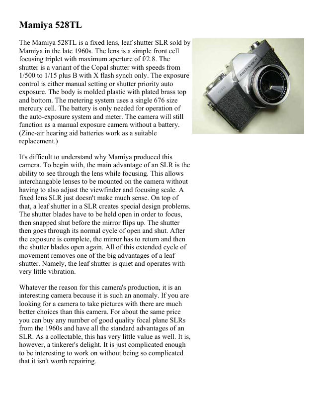
Mamiya 528TL

The Mamiya 528TL is a fixed lens, leaf shutter SLR sold by
Mamiya in the late 1960s. The lens is a simple front cell
focusing triplet with maximum aperture of f/2.8. The
shutter is a variant of the Copal shutter with speeds from
1/500 to 1/15 plus B with X flash synch only. The exposure
control is either manual setting or shutter priority auto
exposure. The body is molded plastic with plated brass top
and bottom. The metering system uses a single 676 size
mercury cell. The battery is only needed for operation of
the auto-exposure system and meter. The camera will still
function as a manual exposure camera without a battery.
(Zinc-air hearing aid batteries work as a suitable
replacement.)

It's difficult to understand why Mamiya produced this
camera. To begin with, the main advantage of an SLR is the
ability to see through the lens while focusing. This allows
interchangable lenses to be mounted on the camera without
having to also adjust the viewfinder and focusing scale. A
fixed lens SLR just doesn't make much sense. On top of
that, a leaf shutter in a SLR creates special design problems.
The shutter blades have to be held open in order to focus,
then snapped shut before the mirror flips up. The shutter
then goes through its normal cycle of open and shut. After
the exposure is complete, the mirror has to return and then
the shutter blades open again. All of this extended cycle of
movement removes one of the big advantages of a leaf
shutter. Namely, the leaf shutter is quiet and operates with
very little vibration.

Whatever the reason for this camera's production, it is an
interesting camera because it is such an anomaly. If you are
looking for a camera to take pictures with there are much
better choices than this camera. For about the same price
you can buy any number of good quality focal plane SLRs
from the 1960s and have all the standard advantages of an
SLR. As a collectable, this has very little value as well. It is,
however, a tinkerer's delight. It is just complicated enough
to be interesting to work on without being so complicated
that it isn't worth repairing.
View original page 1
Page 2 · Read text
McKeown's guide indicates that most of time this camera is
found in non-working condition and of very little value. So,
if you're looking for a good project, get one. You may end
up with one of very few working examples of this camera.
Otherwise, only the die-hard Mamiya collector will find
this camera very interesting or desirable.

The interesting thing about this camera from the viewpoint
of us tinkerers is the way the shutter works. Overall, you
have a standard mirror box mechanism and a mostly
standard leaf shutter. The unique part of the shutter is a
special drive ring located underneath the speed setting cam.
This ring surrounds the outside of the shutter base and
drives the different parts of the mechanism. Unfortunately, I
don't have a a picture of this ring. One reason is that the
ring sits on the shutter base under spring tension and will
not stay put unless you hold it down while setting the speed
cam back on. I needed a third hand to be able to take a
picture!

As you disassemble the shutter, look closely when you
remove the speed cam and you will see this magic ring.
There is a tab on the ring that pushes against a stud on the
blade operating ring. When at its resting position, this tab
forces the blades open. The hook attached to the main
spring cam has a special cut-away that allows the blades to
be pushed open while the shutter is uncocked. On the
outside of the control ring there are several studs. One stud
pushes against a spring operated lever to force the ring back
into position at the end of the cycle. Another stud pushes on
the shutter release. In addition, there is a brass lever
attached to the ring that holds back the diaphragm until the
just before the shutter fires. This allows full aperture
focusing and metering. Study this ring closely to understand
how the shutter is controled.

The auto-exposure system is a fairly typical needle capture
system. The meter unit is rotated by a gear driven screw.
This adjusts the exposure for different shutter speed and
film speed settings. Re-adjusting the meter position turned
into quite an adventure.
View original page 2
Page 3 · Read text
So, be sure and carefully measure the initial position of the
screw that pushes the meter back and forth before
disassembly. I forgot to do this and had to reset the meter
position by trial and error.

This camera came to me with an inoperable shutter and an
stuck focus ring. Fortunately, the shutter simply needed
cleaning to remove the grease on the shutter blades.
However, because of the way the shutter works, you can't
do a simple cleaning of the blades if they become sticky.
The blades are pulled back out of the way and thus the
speed setting cam and control ring have to be removed in
order to get the blades to close. You can't just remove these
parts because the gear that drives the meter position
prevents them from being lifted off. The only way to get the
gear out is to remove the mirror cage and then remove the
worm screw on the other end of the gear shaft. So, it's an
almost complete disassembly just to clean the shutter on
this camera.

As always when working on a plastic body camera, be
careful about overtightening screws. It is easy to strip out
the plastic thread in the screw holes of the body.
                                 To remove the top cover, open the back and hold the
                                        rewind fork while unscrewing the rewind knob.
                                    Unscrew the pin-face screw over the wind lever and
                                                               lift off the lever, washer, bushing and turn plate.
                                 Remove the two screws on each side of the top and
                                             the top will lift off. The shutter relase button falls out.
                                   Watch for the cable release pin located inside the
                                               shutter rlease button. There is a steel bushing around
                                             the wind shaft that lifts off.

                                        Unsolder the wire connected to the hot-shoe.
                                        Unsolder the four wires of the meter. The two CDS
                                          wires go to the yellow and green wires. The red wire
                                    comes up from the battery connector and is soldered
                                               to the blue wire. The CDS cell is located underneath
                                             the reflex mirror. The mirror itself is semi-
                                               transparent. If you look closely you can see the cell
                                         underneath the mirror. I don't know how you would
                                            replace this cell if it is bad!
View original page 3Page 4 · Read text
To remove bottom cover, remove the two screws and
lift the cover off. Unhook the spring clip holding the
lever at the center of the body (red arrow) and lift the
lever off the post of the mirror charging lever.


Next, pull up the leatherette on the front and remove
the four screws underneath. The entire mirror box,
shutter and lens will lift off together.

Remove the two screws in the pentaprism bracket and
lift the prism out.

Look at the left side of the mirror box and study the
way the meter is moved back and forth. The position
of the worm screw needs to be carefully measured
before removal. It is important to get the screw back
in the right position before setting the meter assembly
back in place. Remove the two screws holding the
meter assembly and lift off the meter and circuit
board. Be careful to slide the needle out from the
capture plate withuot bending the needle.

Remove the four screws holding the fresnel screen
bracket and lift the screen out. There are two spring
brackets underneath. Note, you will need to reset the
focus during reassembly.

Remove the two screws on the right side of the mirror
box that holds the box to its bracket. Remove the
screw on the left side located inside the focusing
screen opening and the screw on the left bottom.
There is a return spring that connects the auto-
aperture lever located inside the mirror box. Unhook
the spring. The mirror box can then be lifted off the
front plate.
Loosen the set screws on the meter positioning screw
and slide the screw off. Remove the snap ring around
the shaft.
View original page 4
Page 5 · Read text
Unsolder the black wire at the flash connector.
Remove the shutter retaining nut and the shutter will
lift off the plate.

Begin working on the shutter by removing the rear
lens element. If the focusing ring isn't locked in place
due to dried grease, turn the focus to the infinity
position. Loosen the setscrews in the focusing ring
and lift the focusing ring off. Mark the infinity
position of the lens and then unscrew the front lens
element. Unscrew the center lens element.

Remove the three brass screws and lift the DOF scale
off. Underneath is the ASA ring. This ring will
probably pop up as soon as the DOF scale is off due
to the spring underneath on the ASA setting lever.
Note how this ring drives the meter positioning gear.
Pull the meter positioning gear out.

Turn the lock screw one-half turn and then unscrew
the serrated retaining ring. Lift off the speed setting
ring. The control ring is underneath. It is attached to
the shutter base with a spring.

Look for the shutter click-stop button and spring.
These are located in a tube mounted onto the shutter
base. Remove these so they don't fall out and get lost.

The retard escapement is held with two screws, one at
the end on the base and the other near the pallet.

Remove the flash connector.

At the pallet end of the retard you will see a lever
held in place with a snap ring. This is the lever that
pushes the control ring down against the shutter
blades to force them open. Unhook the spring,
remove the snap-ring and lift the lever off.
View original page 5
Page 6 · Read text
Turn the shutter over and remove the three screws
                                          holding the aperture control. Lift off the brass ring,
                                            operating lever, spacer, and aperture control ring.

                                 Remove the three screws in the shutter base and then
                                             separate the shutter halves.


                                         This image shows the shutter clockworks.


Notes

There is light seal foam around the back of the mirror box. This will probably be rotten and need to
be replaced. Likewise there is foam around the battery compartment.

After reassembly, you will need to reset the focus on the lens and viewer. To set the lens, turn the
lens until sharp at infinity. Loosen the setscrews and turn the focusing ring against the infinity stop
then tighten the screws. To set the viewscreen focus, you have to have the top cover off. Turn the
four screws at the corners of the focus screen bracket until the image in the viewer matches the lens
focus.

All of the mirror box mechanism is on the outside of the mirror box. On this camera there was no
problem with the mirror, so I didn't do any disassembly. Study how the various levers on the mirror
interact with the shutter. The wind lever and control ring points on the shutter need to be engaged
with the mirror box properly during reassembly.
View original page 6From the M. Butkus archive. Original publisher and archive notices are retained.
Check the model and edition against your equipment.
PDF verified 2026-10-10.