Film cameras
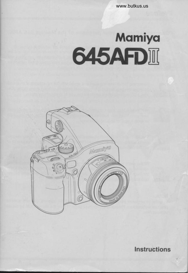
Mamiya 645AFD II User manual
User manual for Mamiya 645AFD II. 112 pages in English. Read the original PDF, download or print a copy without registration.
112 pagesEnglish13.9 MB PDF
Loading your manual…Open PDF directly
Document details
- Brand
- Mamiya
- Model / document
- Mamiya 645AFD II
- Document type
- User manual
- Language
- English
- Pages
- 112
- File size
- 13.9 MB
- Category
- Film cameras
- Document date
- Not specified in catalog
Search available document text
Find a term, then jump to its page in the original PDF. Image-only pages may not be searchable; check the PDF for exact wording and diagrams.
Page 2 · Read text
Preface

       Congratulations on your purchase of the Mamiya 645 AFDII
       Camera.

                 Mamiya pioneered the 645 SLR system camera three decades ago and the
                 Mamiya 645 AFDII, with its TTL auto-focus, auto-exposure, auto-flash and
                     auto-film winding features is the latest Mamiya masterpiece and reflects its
                     long tradition of medium format camera expertise.


                  Combining 35mm handling ease and speed with the advantages of an almost  ,&
                 3x larger image size, it is a full-featured camera, utilizing many digital con-
                         trols, LCD displays and is ready for the age of digital photography.


                            Its high-tech focal plane shutter with speeds up to 1/4000 sec. permits flash
                   sync up Io 1/125 sec. and has an exclusive "Safety Retraction" feature, which
                      protects  it against accidental damage.


                The AE Prism Finder with its many features, protected by a sturdy magne-
                  sium housing, and also the Power Drive Grip, are now integral components of
                     the die cast aluminum camera body, designed for heavy professional use.


                        All the many features, safety interlocks and other important information are
                  covered in detail in these instructions.  lt is imperative that you read them
                   thoroughly before you put your camera to work, in order to ensure proper
                     operation and maximum  results.

        Note:
           In order to acquaint yourself with the functions of the camera, you will want to
          practice without film. Please see bottom of page 11 how the camera can be tested
         without film.


                                                                                                                                                                                                   ,.Jflhr           -                                  -.d#-                                                                                                ,
View original page 2Page 3 · Read text
www.butkus.us


Special Advice To Professional Photographers

Your Mamiya645 AFDII is designed for heavy professional use and willgive you a long
service life if properly maintained. Your camera and lenses have many moving parts
which require periodic lubrication. lts electronic components, too, are subject to wear
and tear and are affected by ambient conditions like dust, sand, sea air, heat and mois-
ture.                                                                      t
lf cameras had odometers like automobiles,   it would be easier to specify servicing sched-
ules. May we suggest that  if you shoot thousands of film rolls per year, you send your
equipment annually for servicing by the Mamiya distributor in your country.

Mamiya 645 AFDII corresponds with digital backs compatible with MSC (Mamiya Serial
Communication  of External) system.
View original page 3
Page 8 · Read text
Venmo @mike-butkus-camera  Ph. 2083
PayPal Name  Lynn@butkus.org      www.PayPal.me/lynnbutkus
View original page 8
Page 9 · Read text
Electronic Dial operations / Liquid crystal Displa
Electronic Dial Operation

                       Position                 Front dial                            Rear dial

                     P                             Program  shift (Px<)P<rPr-)
                    Av                                    Aperture adjustment
 Exposure mode       Tv                                   Shufter speed adjustment
                 M             Shutter speed adjustment                   Aperture adiustment
                   X                                     Aperture adjustment

 Multiple
                          displayed                     Number of additional exposure exposure bufton   ffi
 Auto-bracketing                       Specify the auto bracketing  width
 button            Z4iJdisptayed   Select the number of frames tor auto     Turn the auto bracket ON/OFF
                                                     bracketing

                                                           Flash                                                                 metering                                                                      compensation                         oisptayeo SET button       [!                                             (when using                                                         Metz                                                                        flash and                                                              SCA3952 adaptor)

               Liquid Crystal Display
       All displays on the liquid crystal display consist of " E " and the number of
      places is limited. For this reason, some letters and words are abbreviated.

      Display examples of the main LCD
     \E t         SEr       -=+        tiL ar        -+       Dial Lock
                               (AF supplemental infrared light)       FIF i. |        AF Light           i: \EL _+--_+   Flash Sel (Flash compensation)
   FL              Flash
      h;l: i- --+-_>     Battery
    Eld         END
   Fd+ -'+      Finder Display
     F r r   ______r_  Error
                 OFF  nF  --'-+     frr, ___>  Fb         OnFilm Back       -+    + (Plus)    +
    u      ------+  Under
         tr      '+      Over
     n               Normal
           --=-+
    The functions controlled by the front and back dials can be changed
     using the custom settings feature (See c-l3, 14,1s,16 on page 9o to sty.
View original page 9Page 10 · Read text
www.butkus.us


      Display examples when one of the custom functions is specified
 5E L            Select   f unction No. (Select one of the user functions)
 5f tP +       Tv, Av step (Select step width for Tv and Av)
 i - 5f         Compensation  Value (Set the step width for exposure compensation)
 BFBr +    AF area (Select anAF area)      ->               Spot (Spot)5P  +
 I nPr +        In Print (Select a data type for superimposing  info on the picture)
 i r! 5 +         lris (Hold a specific lens iris value)
Ht            Hold (Hold)
llF  +-+    OP (Not held, released) i g             LEast (Minimum)
5t    ---+-+    STep(Numberof stepsfromtherelease)
H0l d +      Power HOLD (Hold the power setting)
 | - r d +     Cv range (Specify the range of exposure compensation)
 , i.  +        lllumination  (backlight  illumination)
 l'i-UP +      MirrorUP (Minorup)
br [d +       Bracket Cancel (Stop auto bracketing)
 f J   {-+    Cancel (Cancel)
EE  +     One Shot (One shot)
 I'i-br +      Manual Bracket (Use bracketing  in M mode)
  l'l - dF +      Manual Dial Function (Swap the dial functions in the manual mode  )
d-,9f +       Dial Action (Specify a sub-dial forTv and Av mode)
d- df +       Dial Direction  (Dial rotation direction)
P- 5h +      Program  Shift (Shift programs)
CA           Tv,Av Compensation  (Shift Tv and Av)
RE F L        AE,AF Lock (Swap the AEUAFL bufton functions)     ->HELF +     -+      Half Release (Enable a half-press  release on the button)      .+    AE Lock (Specify the operation  of the AE tock button)tqlRF d, +    AF Display (Display an AF focus mark)
F[    *      Focusin(Displayjustthefocusmark)
db5            Difference Between the Setting (Display the difference  in metered brightness  in the M mode)
AnEP -'++     One Push Action (Select the operation  of a one push shift in the M mode)
b- i-, "+     Bulb Limit Time (Specify the max time for a bulb shot)
h-FU +      Bulb Function (Bulb exposure method)
5\nc +      Synchronize  (Specify the synchronous  speed in the X mode)
UFi. 5        Use Flash Shutter Speed (Select a synchronous speed to use in the Av and P modes)
                                                         p modes)i. |    -"+-'>      Limit (Specify a synchronous  speed  limit in the Av andFU  +        Full Range (Specify a synchronous  speed to use in the Av and p modes)
              TTL Compensation (Link the compensation  between TTL metering and exposure compensation)!!L [ +BF -L       AF Light (Specify an AF compensation light operation)(AFy    +       Function Copy (Copy a function)     -+dPF -+      Default (Detaulg
                 Function  Initialize  (lnitialize the functions)i ni  -+noFL +     No Film (Shutter release operation when no film is in the camera)
i.0            Lock (Does not release the shutter unless film is present)
E n  +-'+     Enable (Release the shutter without any film in the camera)
nEFU +        Multi Exposure Function  (Multiple exposure operation)
r,b[  .+     Use Digital Back Custom No. (ldentify the digital back)
    i.iP +     gp
View original page 10Page 14 · Read text
www.butkus.us


     Before Taking
     Photographs

      Preparation
     taking


This chapter describes how to put in the batteries, how to in-
stall and remove the lens. and how to install and remove the
magazine.
View original page 14Page 15 · Read text
Inserting the Batteries  ( IT,?:lffjftJ:lJ" oPerate ,
Be sure to turn the switch of the Shutter Release Button to "L" as shown in the top
illustration, to turn the power off. This prevents electrical damage to the circuits.
Set the shutter release mode selector lever to "L" (to turn the power off).
Use six "AA" alkaline or lithium batteries.
                                  1. Lift the battery case lock lever, turn  it counter
                                      clockwise and pull out the battery holder.


                                2. Insert fresh batteries with tne O and e ends
                                  as shown in the drawing.

                                         I Be sure the batteries are placed with proper
                                             polarity


                                  3. Return the battery holder to its case and lock  it
                                by turning the lever clockwise. Make sure  it is
                                          firmly attached.
   y.2
       S):-..1
       "

* After inserting the batteries, set the date and time. (See page 25.)
View original page 15Page 16 · Read text
www.butkus.us
                Checking the Battery Power

 Set the shutter release mode selector lever to "S" (to turn the power on).
 Check the battery condition in the lower right corner of the main LCD.


                            The batteries are sufficiently charged.  EI


                                 There is little power remaining. Have new batteries
                             on hand.
                             Camera  will still operate.


                                 There is very little power remaining. Camera will not
                                     operate.
                                * Set the shutter release mode setector lever to "L"
                                               (to turn the power off) and replace the batteries
           Flashing                                      with new ones.

                              * When the batteries are spent, "batt" flashes on
                                       the main LCD and the viewfinder's LCD when the
           Flashing                                       shutter release button is pressed.

I When replacing the batteries,'be sure to use six new batteries of the same type.
   not mix different types of batteries or old batteries with new ones.

Number of rolls that can be exposed with a new set of batteries
 At normal temperature (20'C) (68"F)       (under our test conditions)
                              Alkaline battery       l-ithium batteries
120 type film                 Approx. 150           Approx. 400
220 tvpe film                 Approx. 130           Approx. 220
Bulb time                    Approx. 1B hours      Aoprox. 24 hours
-10"c (14'F)
                              Alkaline batterv      Lithium batteries
120 tvoe film                  Approx. 25           Approx.2B0
220 tvoe film                  Aoorox. 25            Aoorox. 200
Bulb time                     Aoorox. 8 hours        Aoorox. 24 hours
View original page 16Page 17 · Read text
Installing the Battery in the Magazine


 The button battery supplies power to the magazine's LCD when the film magazine is
 detached from the camera. When the film magazine  is attached to the camera body, it is
 powered by the camera's batteries.
                                  1. Remove the battery compartment
                              cover screw.
                              Use a coin or suitable screw driver and turn  it
                                       counter clockwise.


                                    2. Insert a battery.
                                              lnsert the battery according to the polarity indica-
                                            tion O in the battery compartment, and close the
                                           battery cover.
                                          Battery used: Sony CR2032 or equivalent
                                          I Be sure to watch correct polarity


 * When the magazine is installed onto the body, the power will be supplied to the maga-
    zine from the camera body.
 * You can take shots without installing the battery into the magazine. However,  if you
   remove the magazine from the body, the magazine does not indicate film sensitivity
    or number of shots.
 * The magazine battery is not equipped with a battery level indicator. When the maga-
    zine LCD panel becomes dark or disappears, replace the battery. As a rough guide-
     line, the battery should last approx. one year.
View original page 17Page 18 · Read text
www.butkus.us
                                 Batteries Care

1. Life of the batteries that come with the camera body is subject to storage conditions.

2. Bolts and fingerprints on terminals may cause loose connection and corrosion. Wipe
  them off before loading the batteries.

3. lt is advised to carry spare batteries when you travel where they may be difficult to
   obtain.

4. Performance  of the battery degrades in low temperature. Keep them warm when in
   cold climate.
   External battery case PE401 is available as an optional accessory.

5. Store the batteries in a cool and dry place, away from direct sunlight.

6. Keep the batteries out of the camera body, when  it is not used for a long time. Leaving
  them in the camera may cause corrosion.

7. Replace the batteries with new ones as soon as they are exhausted. Liquid leakage
  from the battery may damage the camera.

8. Read the warning labels of the batteries for handling of the batteries.
View original page 18Page 19 · Read text
Attaching / Removing Lens

 Attaching
                                       1. Remove the front body cap, just like
                           you would remove a lens, by pushing
                               the lens release button @ backward
                            and then turn the front body cap or the
                                lens itself counter clockwise and lift
                                     out.

                    www.butkus.us


                                To remove the front lens cap, squeeze the shiny
                                        sections together and lift out.


                                  To remove rear lens cap turn  it counter clockwise.
View original page 19Page 20 · Read text
www.butkus.us


                                         2. Attaching the lens
                                         Align the white alignment dot of the lens (on the
                                       shiny flange) with the camera's white dot,  fit the
                                     lens into the camera and rotate  it clockwise until
                                                                              it clicks into place.


* Do not touch the distance ring or other rotating parts during the auto focus opera-
   tion.
* When installing a lens, do not press the lens release button @.


Removing
                                  While sliding the lens release button back @,
                                           rotate the lens counter clockwise until  it stops
                              and lift  it off.


* After removing the lens from the camera body, protect both ends by attaching the
  caps.
* Oil, dust, fingerprints or water on the electronic contacts could resutt in matfunction
  or corrosion. Wipe such impurities off with a clean piece of cloth.
View original page 20Page 21 · Read text
Attaching / Detaching the Magazine

  Installation and removal of the magazine and its dark slide
 Unless the dark slide is inserted in the magazine, you cannot install and remove the
  magazine. When the camera batteries are low or they are not installed, the dark slide
  cannot be removed although the magazine can be mounted or removed.

 Before installation
                                             1. Remove the magazine protection cap.


                              Remove the camera rear body cap while putting
                                  a finger into the notch and slide the cap down.


 Attaching
                                          2. Match the groove on the magazine body
                                        coupler with the holder bracket (lower) of the
                                camera body and snap the magazine into the
                                         body.
View original page 21Page 22 · Read text
www.butkus.us


                                                3. Then you move them together like you close
                                 a book until they lock and you hear the focal
                                      plane shutter open.


     Shutter Safety Retraction
   The precision shutter blades are made of very thin hyper-duralumin and could be
   damaged if unprotected. Therefore the camera is designed to automatically re-
     tract the shutter into the open position when the magazine  is removed. When  it is
    reattached the shutter automatically closes and is ready for normalfunction. (Bat-
     teries must be in camera).

Detaching
                                          1. lnsert the dark slide into the magazine.


                                            2. With your thumb first push button 6 down
                                 and then simultaneously button @ in. The
                                  magazine  will separate  itself from the camera
                                        body.
                                    * When the magazine is removed, the shutter will
                                         automatically open, as explained above, un-
                                      der "Shutter Safety Retraction"
                                         . Film winding and shutter release are also
                                           locked.
View original page 22Page 23 · Read text
Diopter Adjustment

 Look through the viewfinder and make sure that the focus frame (Rectangle with
 Circle) is in sharp focus. lf it is not, turn the diopter adjustment  dial in the "-" direction
  if you are nearsighted,  in the "+" direction  if you are farsighted.  lf this is not sufficient
 you may require an optional diopter correction lens. See below.


 * Point the camera at a bright, plain object such as a white wall when making this
    adjustment.


                            tA'
                                               -\./-   'G


          Diopter does not match.                         Diopter matches.

             Range of adjustment of diopter correc-
                  tion lenses (Optional accessory)
                             Diopter eorrection lens       Bange of adjustment
                           DE401 (standard)                     -2.5 to +0.5
                      DE402  (for nearsighted  users)              -5.0 to -2.0
                       DE403  (for farsighted users)              0 to +3.0
View original page 23Page 24 · Read text
www.butkus.us
            Replacing the Diopter Correction Lens

                                                      1. Remove the lens supplied with the finder by
                                                          pulling  it downward.


                                                      2. Push the replacement diopter correction lens
                                            upward into the viewfinder's eyepiece frame
F,                                                              until  it clicks into place.


           *  lf there is dirt or dust on the lens surface, remove it with a blower or sweep it off
               gently with a lens brush.
           *  lf there are fingerprints or dirt on the lens surface, wipe it off with a piece of clean,
                soft gauze.
           * Using solvents could discolor the diopter correction lens frame.
View original page 24Page 25 · Read text
Setting the Index Number

The index number consists of 4 digits (0000 to 9999). The index number is stored in
the camera body so that when replacing a series of roll film holders, the camera will
superimpose sequential index numbers on exposures. This is effective when exposing
and managing a large number of rolls of different types of film.
I Although the index number consists of 4 digits, only the lower 3 digits are superim-
  posed on the exposure

                                               1. Turn on the power.
                                    Set the shutter release mode selector lever to
                                        "S" or t'G.tt

                                         2. Press and hold down the exposure mode dial
                                      lock-release button. Then, turn the exposure
                             mode dialto the CF position.

                                            3. Turn the front dialto select custom number
                                      c-36.
                              The display will immediately show C-36.

                                                                         'rt Turn the dial on either side to select a custom
                                       .number.
                                         4. Press the set button
                                           After pressing the set button 6, you willsee
                                     the index setting display.

                                               5. Turn the front and back dials to set the index
                                   number. (4 digits). Turn the front dial to select a
                                              digit in the index number (the selected digit
                                            blinks) and then change the number by turning
                                     the rear dial.
                                                           rt Turn the front dial until "HL" blinks, so that
                                   the camera always superimposes the in-
                                  dex number specified. When "UP" is blink-
                                          ing, each time you release the shutter the
                                    index number will increase and be super-
                                imposed on the next exposure.
View original page 25Page 26 · Read text
www.butkus.us
I

           6. After the index number is specified, press the set button @ for approximately one
        second to store the setting.
       * The custom setting mode of the superimpose is not set under default. Please set at
         custom setting (C-4 on page 88). lf a film is not loaded, the index number does not
            count.
        * The starting index number can be set at will. For example, when shooting in different
           places or for different purposes, you can classify the photos by changing the start-
            ing number of any of the digits.
       * Once the total number of photos taken reaches 999, counting starts over from 001.
          000 can also be set using the index number setting procedure.
       * After 60 seconds, the index number setting mode is canceled and the setting is not
            registered in memory.
        * Custom settings remain in the memory even when the shutter release mode selector
            lever is set to "L" (turning the power off).
        * When the exposure mode is not set to the CF position and you press the set button
            for approximately 2 seconds, you can check the index number previously stored.
           Pressing the set button again will let you to check the "month-date-year" and "hour-
           minute- seconds" settings.
View original page 26Page 27 · Read text
Setting Date and Time

                                                  1. Turn on the power.
                                       Set the shutter release mode selector lever to
                                          "S" or "C."

                                            2. Hold down the exposure mode dial lock-
                                         release button and turn the exposure mode dial
                                              to the CF position.


                                                  3. Turn the front dial to select custom number C-
                                             35.
                                  The display will immediately show C-35.


* Turn the dial on either side to select a custom number.

4. Press the set button
After pressing the set button @, the display will change to the date setting mode.
View original page 27Page 28 · Read text
www.butkus.us


                                                5. Turn the fronl and back dials to set the date
                                  and time.
                                    Turn the front dial to select "month-date-year"
                                        or "hour-minules-seconds"  and change the
                                     value by turning the rear dial.


6. After the date and time are set, press the set button @ for approximately one
second to store the settings.

*  lf you stop pressing buttons or turning dials while changing settings tor 60 seconds
   or more, the camera wlll automatically exit the setting mode and any changes to the
  current setting will not be stored.
* When not in the GF exposure mode,  if the set button is pressed for approximately
  two seconds the display will show the Index number, Press the set button again to
  check the date and time.
View original page 28From the M. Butkus archive. Original publisher and archive notices are retained.
Check the model and edition against your equipment.
PDF verified 2026-10-10.