Camera accessories
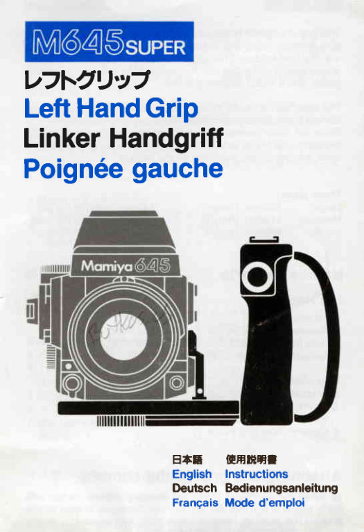
Mamiya M645 Super Left Hand Grip User manual
User manual for Mamiya M645 Super Left Hand Grip. 12 pages in German, French, English. Read the original PDF, download or print a copy without registration.
12 pagesGerman, French, English0.9 MB PDF
Loading your manual…Open PDF directly
Document details
- Brand
- Mamiya
- Model / document
- Mamiya M645 Super Left Hand Grip
- Document type
- User manual
- Language
- German, French, English
- Pages
- 12
- File size
- 0.9 MB
- Category
- Camera accessories
- Document date
- Not specified in catalog
Search available document text
Find a term, then jump to its page in the original PDF. Image-only pages may not be searchable; check the PDF for exact wording and diagrams.
Page 2 · Read text
V7t'2Uva
LeftHandGrip
LinkerHandgriff
Poign6egauche


                  ETT    OIHHffI
                       English Instructions
                          tleutsch Bedienungsanleitung
                      FrangaisMode d'emploi
View original page 2Page 3 · Read text
V7t-2U'Ya
(*. T.dr) 9- =, tb7 I a 9-N2t
Left Hand Grip
(Large, Medium and Small Sizes) with Connector N
Linker Handgriff
(GrOBe,mittelgr6Be und Kleine Ausftihrungen) mit Adapter N
Poign6egauche
 (Tailles grande, moyenne et petite) avec Connecteur N


                     www.orphancameras.com
View original page 3Page 7 · Read text
liEEISllt
This grip is usedfor holdingthe camerawith your lefthand.Avail-
able in three sizes and forms, it allows the user to photograph
with the best holding.The grip is providedwith a releasefunction,
an accessoryshoe (on which is mountablea clip-onelectronic
flash),and a tripod mountingscrew.

The attachedconnectorN ensurescordlessinterlockingwiththe
camera'selectromagneticreleaseand synchroterminal.
Since the cable releasesocket is providedon the connectorN,
the connectorN can independentlyuse a shutterrelease,a self-
timer, etc. which are availableon the market.

Three sizes:
Large:   128mm (height)     140mm (aroundthe grip)
Medium: 118mm (height)     125mm (aroundthe grip)
Small:   108mm (height)      1 1Smm (aroundthe grip)

Names of Parts
Left Hand Grip
 1.Accessoryshoe             9.Tripodsocket
 2. Releasemark (whitedot)    10.Hand strap
 3. Lock mark (red dot)       11.Handstrapadjustingscrew
 4.Release/lockmark
             (whitedot)      Connector N
 5. Release/lockring          l2.Synchroplug
 6. Releasebutton             13.Auxiliaryreleaseplug
 7.'Terminaladapter          14.Cablereleasesocket
   electronicconnectingsocket lS.Contactfor left Hand grip
 8. Camera mountingscrew
                   www.orphancameras.com
View original page 7Page 8 · Read text
Attachingthe grip to the camera
   O  Insertthe connectorN into the auxiliaryreleasecontactand
      flash synchro terminal on the camera body, as shown in the
     photo. (The auxiliaryreleasecontactcan be exposedby sliding
     the camera body'sside cover leftward.)                    -ceifiErafiouiitingt---grruith              tn6                              screw o'ii thd-grip,sdcuGly fix the
      grip to the tripod socket at the bottom of the camera body.
    Make certain that the electroniccontact of the connectorN is
      correctlyinsertedinto the grip's electroniccontactsection.

  How to use
    O Turn the release/lockring on the grip and alignthe whitedot
      indicatoron the ring with the releasemark (whitedot) on the grip
     body.
    O  Set the shutterreleaseselectoron the camerato the normal
      positiontr.
   @ The shutter can be tripped by depressingeither the shutter
     release button on the grip or the shutterreleasebuttonon the
     camera body.
         (lf the camera'sshutterreleaseselectoris set to the mechanical
      shutter position[yellow],the shutterwill not trip even when you
     depressthe shutterreleasebuttonon the grip.)

     [Release lock]
     Turn the release/lockring on the grip, and set the white dot indi-
      cator on the ring to the red dot indicator(release/lockmark) on
          '     the grip body. The grip's shutter releasebutton will be locked,
     preventingthe shutterto be tripped on the grip. However,the
      shutterreleasebuttonon the cameracan be activated.
     To preventaccidentalshutteractivation,or duringtransportation,
    when the camera is not in use, be sure to lock it by setting its
      shutterreleaseselectorto the red dot.


     o In case the electroniccontactof the grip or the connectoris
     stainedwith oil, dust, etc.,impropercontactmay cause malfunc-
      tion. When the contacthas been stained,wipe it carefullywith
     clean cloth.
     o The hand strap can be adjustedby looseningthe adjusting
     screw with a coin.
View original page 8Page 9 · Read text
GE
Mit diesemGriff kdnnenSie die Kamerazum Arbeitenbequemin
der linkenHand halten.Eine Auswahl an drei unterschiedlichen
GroBen bietet fur jede Hand den richtigenGriff. Der Handgritf
verfugtribereinenAusldser,einen Zubehorschuhzum AnschluB
eines Elektronenblitzgeriitsund eine Stativschraube.
Das Anbringenvon Adapter N ermdglichtkabelloseVerbindung
mit den elektromagnetischenAusl6serund den Synchronkontakt
der Kamera.
Dank der am Adapter N vorgesehenenDrahtausloserbuchse
kann Uberden AdapterN eine separateAuslosungder Kamera
erfolgenund daruberhinausein als Sonderzubehorerhdltlicher
Timer usw. angeschlossenwerden.

Drei GroBen:
GroB:    128mm (Hohe)      140 mm (Gritfumfang)
MittelgrdB:118mm (Hohe)      125 mm (Griffumfang)
Klein:    108mm (Hohe)      115 mm (Griffumfang)

Bezeichnungder Teile
Linker Handgriff
 l.Zubehdrschuh               8.Kamerabefestigungsschraube
 2.Ausl6semarke             9.Stativfassung
  (weiBerPunkt)            10.Handriemen
 3.Verriegelungsmarke     1 1 .Handriemen-Einstellschraube
   (roterPunkt)
 4. Freigabe/Verriegelungs-     Adapter N
  Marke(weiBerPunkt)      12.Synchronkontakt
 5. Freigabe/Verriegelungs-Ring 13.Hilfsausloser
 6.Ausl6ser                14. Drahtausl6serbuchse
 7. Adapterfur elektronische   15.Kontaktfur Handgriff
  Kontaktfassung  www.orphancameras.com
View original page 9
Page 10 · Read text
Anbringendes Handgriffsan der Kamera
$  Wie im Foto gezeigt, den Adapter N an Hilfsausldserund
Synchronkontaktder kameraanbringen.(DurchVerschiebender
seitlichenKameragehiiuseabdeckungnach links wird der Syn-
chronkontaktf reigelegt.)
@ Den Handgriffmit Hilfe der Kamerabesfestigungsschraubd6
sicheran der Stativbuchseam Bodender Kameraanschrauben.
Sicherstellen,daB die elektronischenKontaktevon Adapter N
korrektin die entsprechendePositiondes HandgriffseingepaBt
werden.

Bedienung
Q Den Freigabe/Verriegelungs-Ringdes Handgriffsdrehenund
den weiBen Punkt am Ring mit der Freigabemarke(weiBer
Punkt)des Handgriffsausrichten.
@ Den Auslose-Wdhlerder Kamerain Normalstellung! setzen.
@ Sie konnendie Aufnahmemachen,indementwederder Aus-
l6ser des Handgriffsoder der Ausldser der Kamera gedrUckt
wird.
(Wenn der Ausl0se-Wdhlerder Kamera auf eine mechanische
VerschluBzeit(gelbe Position)eingestelltist, erfolgt keine Aus-
ldsung,selbstwenn der Ausl6serdes Handgriffsbet6tigtwird.)


IAusl6sesperre]
Den Freigabe/Verriegelungs-Ringdes Handgriffsdrehen und
den weiBen Punkt am Ring mit dem roten Punkt (Freigabe/
Verriegelungs-Marke)des Handgriffs ausrichten. Auf diese
Weise wird der Ausloserdes Handgriffsgesperrt.Der Ausloser
der Kamerakann jedoch weiterhinbet6tigtwerden.
Bei Nichtverwendungder Kameraoder wiihrenddes Transports
den Auslose-Wdhlerauf den roten Punkt setzen, um einer un-
beabsichtigenAusl6sungvorzubeugen.

 o Verschmutzungder elektronischenKontaktedes Handgriffs
oder ein unsaubererAdapter N konnen zu Betriebsstdrungen
fuhren.
VerschmutzteKontaktesorgfdltigmit einemsauberenTuch reini-
gen.
 o Die Linge des HandriemensldBt sich durch Drehen der
 Einstellschraubemit einerM0nzeoderdhnlichemwunschgemiB
 einstellen.
View original page 10
Page 11 · Read text
E
Cette poign6e s'utilise pour maintenirI'appareilavec la main
gauche. Disponibleen trois formes et tailles, cette poign6e
permet d'effectuerdes prises de vues avec la meilleureprise.
Elle est for.jrnied'une fonctionde d6clenchement,d'un patinac-
cessoire (sur lequel on peut installerun flash 6lectroniqued
mAchoires)at d'une vis de montagedu tr6pied.
Le connecteurN fourniassureun accouplementdanscAbleavec
la borne synchro et de d6clenchement6lectromagn6tiquede
I'appareil.
Comme la fiche de d6clenchementdu cAble est fourniesur le
connecteurN, celui-cipeut utilisers6par6mentun dispositifde
d6clenchementde l'obturateur,un chronorupteurautomatique,
etc. qui sont disponiblessur le march6.

Trois tailles:
Grande: 128mm (hauteur)  140 mm (autourde la poign6e)
Moyenne: 1 18 mm (hauteur)  125 mm (autourde la poign6e)
Petite:   108 mm (hauteur)  1 15 mm (autourde la poign6e)
D6signation des pidces
Poign6e gauche
1. Patin accessoire             8.Vis de montagede l'appareil
2. Repdrede d6clenchement   9.Raccorddu tr6pied
  (pointblanc)               l0.Courroiepour la main
3. Repdrede blocage         11.Visde r6glagede courroie
  (pointrouge)
4.Repdrede d6clenchemenV COnnecteur N
  blocage(pointblanc)       12.Fichesynchro
5.Baguede d6clenchement/  13.Fichede d6clenchemenl  blocage                                    auxiliaire
6.Boutonde d6clenchement     f +.Fiise de d6clenchementde
7. Fiche de raccordement        cAble
  6lectroniqued'adaptateurde  l5.Contactpourpoign6egauche  borne
Fixation de la poign6e i  I'appareil
Q  Introduirele connecteurN dans le contactde d6clenchement
auxiliaireet la borne synchro du corps de I'appareil,comme
illustr6para la figure. (Le contact de d6clenchementauxiliaire
peut 6tre expos6en faisantglisser le couverclelat6raldu corps
de l'appareilvers la gauche).
@ Avec la vis de montage de I'appareilsur la poign6e,fixer
fermementla poign6eau raccorddu tr6piedd la partieinf6rieure
du corpsde I'appareil.
 Veiller d ce que le contact 6lectroniquedu connecteurN soit
 ins6r6correctementdans                     www.orphancameras.comla sectionde contact6lectroniquede
View original page 11
Page 12 · Read text
Commentutiliser cette poignee
O Tournerla bague de d6clenchemenVblocagesur la poign6e
et alignerI'indicateurdu repdreblancsur la bagueavec le repdre
de d6clenchement(pointblanc)sur le coprsde l'appareil.
@ Reglerle s6lecteurde d6clenchementde I'obturateursur I'ap-
pareild la positionnormaleE.
@ L'obturateurpeut etre d6clench6en pressantsoit le bouton
de d6clenchementde l'obturateursur la poignee,soit le bouton
de d6clenchementde l'obturateursur le corps de l'appareil.
(Si le s6lecteurde d6clenchementde I'obturateurde l'appareil
est 16916sur la positiond'obturateurm6canique[jaune],I'ob-
turateurne se d6clencherapas m6me si I'on pressele boutonde
d6clenchementde l'obturateursur la poign6e).

IVerrouillage de d6clenchementl
Tourner la bague de d6clenchemenVblocagesur la poign6eet
r6gler l'indicateurde repdre rouge (repdre de d6clenchemenV
blocage)sur le corpsde la poign6e.Le boutonde d6clenchement
de l'obturateurde la poign6esera bloqu6,emp6chantainsi le
d6clenchementde I'obturateursur la poign6e. Cependant,le
boutonde d6clenchementde l'obturateurde I'appareilpeut 6tre
mis en focntion.
Pour 6vitertout d6clenchementpar m6gardede l'obturateur,ou
durant le transport,lorsquel'appareiln'est pas utilis6,veillerA
bien bloqueren r6glantle s6lecteurde d6clenchementde l'ob-
turateursur le repdrerouge.

 r Au cas ou le contact6lectroniquede la poign6eest souill6par
de I'huile,poussidre,etc., un contact incorrectpeut causer un
mauvais fonctionnement.Dans ce cas  il sera n6cessairede
nettoyersoigneusementavec un chiffonpropre.
o La courroiepour la main peut 6tre 169l6een desserrantla vis
de r6glageau moyend'unepidcede monnaie.

                                                                 -rirEfb
View original page 12From the M. Butkus archive. Original publisher and archive notices are retained.
Check the model and edition against your equipment.
PDF verified 2026-10-10.