Film cameras
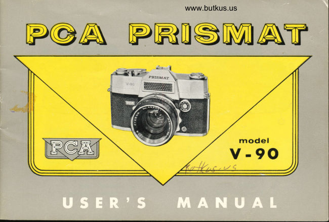
Mamiya PCA Prismat V-90 User manual
User manual for Mamiya PCA Prismat V-90. 24 pages in English. Read the original PDF, download or print a copy without registration.
24 pagesEnglish6.6 MB PDF
Loading your manual…Open PDF directly
Document details
- Brand
- Mamiya
- Model / document
- Mamiya PCA Prismat V-90
- Document type
- User manual
- Language
- English
- Pages
- 24
- File size
- 6.6 MB
- Category
- Film cameras
- Document date
- Not specified in catalog
Search available document text
Find a term, then jump to its page in the original PDF. Image-only pages may not be searchable; check the PDF for exact wording and diagrams.
Page 4 · Read text
www.butkus.us
15. Cartridge Chamber                           20.  Sprocket Release
16. Sprocket                                           2t.   Synchroflash Terminal
17. Take-Up Spool                                   22.   Accessory Clip
18. Distance Scale                                23.  Strap Eyelets
19. Depth of Field Scale                           24.  Tripod Socket
View original page 4
Page 5 · Read text
BEFORE TOADING FOR PICTURE-TAKING

   Film-loading is done in very much the same manner as with other 3S-millimeter miniature
cameras. However, because the PCA PRISMAT is a single-lens reflex camera of'special
design and construction, its principal features and its workings will first be explained.
  VIEWFINDER AND FOCUSING
  Because the PCA PRISMAT is a single-lens reflex camera, it has no separate view-
fnder. The light entering the main lens is deflected upward by a hinged mirror inside the
camera to form an image on a ground-glass screen which is visible through the eyepiece
 (6) and pentaprism in true orientation. There is interposed between the hinged mirror
and the pentaprism a Fresnel lens and condenser to give uniform brightness to the entire
viewfinder field. There is also interposed a prismatic coupled rangefinder so that focusing
of the P.CA PRISMAT can be accomplished speedily and accurately by means of a
split-image focusing zone at the center of the field of vision.
  When a subject is sighted through the eyepiece, there will be seen within the clear center
circle a rectangle bisected by a horizontal line. If the portions of the subject, on which
focus is to be adjusted, falling within the bisected rectangle are not in true vertical align-


                                                                                                                                                                                                                                                .l           i
View original page 5Page 6 · Read text
www.butkus.us

nlent, the camera is
out of focus. Turn                          .:j
focusing ring (3)                      .::,,
and bring the parts
enclosed by  the                            i;.i
upper and lower                               {
halves of the rec-
tangle   (focusing
zone) into correct alignment. The distance between the camera and subject then can be
read off the distance scale (18).
  When focusing, be sure that your eye is at dead center of the eyepiece (6), and that the
portion of the subject, which must be brought to correct focus, falls squarely over or in the
center of the focusing zone. This caution is particularly necessary when shooting at close
ranges.
  Do not attempt to focus b1' means of the sharpness of the image visible in the view-
finder field. True focus is obtained by the split-image focusing zone.
  Because sighting and focusing is done through the picture-taking lens, there is absolutely
View original page 6Page 7 · Read text
no parallax due to disparity of the optical axis; while interchangeable lenses of varying
 focal length always give full coverage of the viewfinder field. The magnification of the
 viewfinder image when using the standard lens (f:  gmm) is x .76.
  When the shutter button is pressed, and the shutter mechanism is released, th6 view-
finder image is blacked out by the movement of the hinged mirror. Recocking, by operat-
 ing cocking lever (1), will return hinged mirror and aperture to viewing position.
  The markers visible along the right edge of the viewfinder frame are for exposure ad-
justment by means of the built-in exposure meter. Explanation of this function is given
below.
  AUTOTIAIIC APERTURE
  In order to provide the viewfinder the maximum brightness when sighting and focusing,
the aperture opens up fully (tll.9 in the case of the standard lens) when the cocking
lever is operated. When the shutter button is pressed, the aperture automatically closes
down to the previously adjusted tl  setting, and exposure of the film is effected at
this value.
 COUPTED EXPOSURE METER
 The built-in exposure meter of the PcA PRISMAT is coupled to the shutterspeed
View original page 7
Page 8 · Read text
www.butkus.us

dial (4) and the aperture dial (5) bV means
of a cursor (blue pointer) visible at the right
edge of the viewfinder field, which is brought
into alignment with the exposure meter
needle (slim opaque marker). Moving either
the shutterspeed dial (4) or the aperture
dial (5) will cause the cursor (transparent
blue pointer) to move. Deflection of the
exposure meter needle is caused by the in-
tensity of the light reflected by the subject,
impinging on the photocell through the
photocell window (8). When the cursor is
in true alignment with the exposure meter
needle, the exposure controls (aperture and  shutterspeed) are properly set for correct
exposure of the film.
  However, when actually taking pictures, the filmspeed dial (7) mttst first be set at the
ASA number (speed rating) of the film in use.  Failure to make this adjustment rvill result
View original page 8
Page 9 · Read text
in incorrect coupling of the built-in exposure meter to the exposure controls.
  Shutterspeed and aperture settings are changed by turning the respective dials (4 and b).
Shutterspeeds may be changed either before or after cocking. With aperture settings,
however, it is more convenient to adjust after the cocking lever (1) has been operated to
permit viewing and focusing.
  COCKING, AND SHUTTER, OPERATION
  When the cocking lever (1) is swung through its stroke by means of the thumb, the
film is advanced one frame, and the shutter mechanism is cocked. The lever will spring
back if  it is released. It is preferable, however, to ease it back into original position
gently.                                                                                                                                                  i
  The cocking lever (1) remains locked, after cocking, until the shutter is released bv
pressing the shutter button (2).
 When the MXV selector (10) is set at " V ", the built-in self-timer (shutter action delay)
is brought into action. The shutter will operate approximately 10 seconds after the shutter
button is pressed. Moving MXV selector (10) to  (' V " can be done either before or
after cocking.
  Caution l.  Operate cocking lever (1) or shutterspeed dial (4) only after shutter action
View original page 9Page 10 · Read text
www.butkus.us
has been completed. This caution applies particularly to B
setting (bulb-shutter remains open for as long as shutter
button is kept depressed) and to slow shutterspeeds (1 and
1/2 second).
  Caution 2. Do not operate cocking lever while built-in
self-timer (shutter operation with MXV selector at " V ")
is in action.
  Caution 3. When using neither self-timer nor synchro-
flash, keep MXV selector (10) at " X ".
  LENS CHANGE
 The PCA PRISMAT is designed for use at will of
                                                            thethree types of lenses; the standard F 1.9, f -48 mm ;
F 3.5, f:38mm wide angle; and the F 3.5, f-100mm
telephoto.
  When removing the standard lens from  its mount, keep
depressed in direction of arrow the lens catch (11) with
the left thumb, grip with the right hand the lens barrel
View original page 10Page 11 · Read text
where the depth of field scale (19) is engraved, and turn
                            lens barrel counterclockwise   until red dot comes into
                              alignment with red triangle  (shutterspeed index mark).
                       Then the lens barrel can be  lifted clear of the rhount.
                                    (Fig. A, B and C)
                     To mount standard  lens on body, match red dot on
                             lens barrel with red  triangle on mount. Push lens
                                           thumb, then turn lens barrel
                                                       in position when the lens catch is
  Caution l.  When removing and replacing lens, always grip lens barrel at depth of field
scale (19) position and never by the focusing ring (3).
  Caution 2. When the lens is removed, either the hinged mirror or the shutter vanes
will be exposed. On no account touch these delicate parts. If there is any speck of dust
on these parts, remove by squirts of air from a bulb syringe.
  Caution 3. After refitting lens on mount, always move aperture dial from fll.g to f/22
or vice versa to ensure proper coupling of iris diaphragm mechanism.

                                                                                                                                                                        .1 -
                                                                                                                                                                                                                                                  ' "1rl:                                                                                                                                            7',J                                                                                                                                                          )
View original page 11Page 12 · Read text
www.butkus.us

             FILM TOADING

  Standard 35-millimeter miniature film is accepted by
the PCA PRISMAT, monochrome or color, 20 or 36
exposures per roll.   Standard safety cartridges or the
special MAMIYA cassette for users of bulk or dark-
room loading film can be used. When loading camera,
however, avoid direct sunlight, work in the shade under
subdued light.
  1. When backlid catch (I2) is pulled out, the backlid
is released.
  2. Swing backlid fully open, then pull out rewind
crank (13). Place loaded safety cartridge or special
cassette, knob end down, in cartridge chamber (15).
Pull out a few inches of the film, and fit end in  slit
of take-up spool (L7). Wind at least a turn on take-up
spool, seeing to it that the perforations engage sprocket
View original page 12Page 13 · Read text
teeth. Take up slack by turning rewind crank (13) in
                                   direction of arrow; then snap shut the backlid. (See                      {f'                                    Figs. I, 2, 3, and 4).
                               3.  Operate cocking lever (1) and release shutier by
                               pressing shutter button (2).  Repeat two or  three
                         such blank shots until exposure counter (14) moves
                           from triangle mark to numeral 1. You are now readv
                                   for your first picture.           'ry;     lio
                                        iifi,                               4. Turn filmspeed dial (Z) and set at ASA rating of
                              *r*u',!')l'''      ,i,,il,                                                                                              ti.,i,,l    the film in use. The red dots indicate ASA 10, 32 and 40.                                                                                                                          ,r.iilr,.,
                 COUPTED EXPOSURE METER
  1.  First, make sure that filmspeed (ASA) dial (7) is set at the ASA rating of the film
in use.
  2.  Next, set shutterspeed dial (4) at desired shutterspeed.
  3.  Sight subject through eyepiece. The slim dark marker (exposure meter needle) rvill
indicate the brightness of the subject-matter.
View original page 13Page 14 · Read text
www.butkus.us
        4. Turn aperture dial (5) so that the cursor (transparent blue marker) comes into
       exact alignment with the exposure meter needle. The exposure controls (shutterspeed
      and aperture) are now set to give correct exposure of the film.
       S. When alignment of the cursor and the meter needle cannot be obtained, that is to
      say the cursor cannot be brought into overlap position even at either maximum or
      minimum aperture size, re-set shutterspeed at slower or faster position then adjust aperture
        dial (5).
                                                                                                          scale        6.  Shutterspeed diat (4) must be set in click-stop position (at any one of the
                       may be at any point within the scale range since adjustment  isI      graduations). Aperture
        continuous, not in stePs.
 I        T. The shutterspeed dial (4) may be used for adjustment of the cursor if desired. In
        this case, however, the cursor wilt jump in steps, and fine adjustment by the aperture dial
                                                                                        extremely        (b) will be necessary. Also, excessively slow shutterspeed in combination with
       small aperture may be obtained.
                                                                                       exposure         Caution 1. When using the coupled exposure meter to obtain the correct
         settings, make sure that the photocell window (8) is not obstructed in any way. Otherwise
       the meter needle indication will not be correct.
View original page 14Page 15 · Read text
Caution 2.  If, with shutterspeed at 1 and with aperture fully open (fll.g with the
standard lens), the exposure meter needle remains at the low end of its range, beyond the
reach of the cursor, the subject is not bright enough to register properly on the film.
  Caution 3.  If, with shutterspeed at 500 (1/500 second) and with aperture at 22'(f.122),
the exposure meter needle is deflected upward beyond the range of the cursor, the bright-
ness is such that overexposure of the film will be caused. In this case, a filter must be
used to reduce the intensity of the light transmitted by the lens. However, the main
subject itself may not be excessively bright, and the overexcitation of the exposure meter
may be due to extraneous light (such as direct sunlight on the photocell window). Make
sure that conditions are normal.
  Caution 4.  It is therefore advisable to measure the brightness of the subject at as close
a distance as is practicable, catching only the light reflected by the subject. With the
exposure determined in this way, the cursor and the meter needle not necessarily be in
alignment when actually shooting the subject from a greater distance.
  Caution 5. When taking pictures of subjects that cannot be approached, measure bright-
ness by training camera on foreground to eliminate much of the sky.
  Caution 6. Under reverse lighting conditions, or when subject is photographed against
View original page 15
Page 16 · Read text
www.butkus.us
         the sky, be sure to measure brightness of the sub;ect only; otherwise underexposure of
         the subject will result, and a silhouette effect will be obtained.
           Caution ?. When a filter is in use, compensation is necessary. This can be readily
          effected by means of the filmspeed dial (7). If, for instance, with the filmspeed dial set at
         200 f.or film of ASA 200 rating, a filter with absorption factor of X 2 is in use, simply shift
         the filmspeed dial setting to 100 before matching cursor and exposure meter needle. If the
         absorption factor of the filter is x 4, shift filmspeed dial to 50.

                                  CAI'IERA GRIP
rl                                                                                      and  1-        Supporting the weight of the camera on the palm of the left hand, the left thumb
                                                    The right hand grips the right a      index finger are made to grip lightly the focusing ring (3).
         side of the camera, with the ball of the right index fingertip resting lightly on the shutter
        button (2), and the thumb on the cocking lever (1).Ft
          Bring camera up to eye level, and a steady grip is achieved. (Fig. A)
       When adjusting exposure controls by means of the coupled exposure meter, merely
         shift grip of left thumb and index finger to the aperture dial (5) or the shutterspeed
IlFl         dial (4).

lrI
View original page 16Page 17 · Read text
ii


                                                                                                                                                                                          ji.+


 When using camera in vertical position, first set exposure controls and focus in normal
position, then swing cocking lever side up, supporting weight of camera with the left
hand at the left side, now facing downward. Keep left elbow tight up against your body.
(Fig. B)
                                                                                      use   If the cocking lever side is facing downward, support weight by right hand, and
right thumb to operate shutter button (2). Steady camera by means of the left thumb
and index finger gripping the focusing ring (3). Keep right elbow tight up against your
bcdy. (Fig. C)
  These basic grips are used with any of the interchangeable lenses.
View original page 17Page 18 · Read text
www.butkus.us

                         FOCUSING
 When the cocking lever is operated, and swung fully through its stroke, the fikn
                                                                                               theis advanced, the shutter mechanism is cocked, and the viewfinder is activated with
aperture fully open.
                                                                                             subject  While sighting the subject, turn focusing ring (3) so that the split-image of the
seen in the focusing zone at center of the viewfinder field becomes correctly aligned.
  1. For ease of judging correct alignment of the subject, choose clearcut vertical lir'es
such as poles, tree trunks, window frames, and nose and cheek lines'
  2. When taking vertical position pictures, first focus in normal horizontal position, then
turn camera on side for composing and shooting.
                                                                               will be indi-  3. Once the subject is in focus, the distance between camera and subject
                                                                                         becated on the distance scale (18). The available depth of field (focusing tolerance) will
                                                          necessary to check availableshown on the adjacent depth of field scale (19). When it is
depth of field with higher precision, consult the depth of field tables.
                                                                      in usual w?Y,  4. When using infra-red film in conjunction with red filters, adjust focus
then, noting the distance indicated on the distance scale, shift this reading to the index
View original page 18Page 19 · Read text
mark " R ".  This is necessary in order to compensate for the shift in focus due to the
shorter wavelength of infra-red rays.
DEPTH OF FIELD
  Depth of field is the term applied to focusing tolerance at a given distance. If  the
camera is focused on a certain subject at a distance of say 15 feet, there is available,
depending on the aperture setting, a certain leeway in front of and behind the subject in
which objects will register with adequate sharpness. This leeway is known as " depth of
f;eld."
  The following are the attributes of depth of f;eld:
  1. Depth of field varies with aperture size: smaller the aperture the greater the depth.
  2. Depth of field varies with focused range: greater the distance the greater the depth.
  3. The shorter the focal length of the lens, the greater the depth of field.
  4. D:pth of f;eld is greater behind the object in exact focus than in front.
  The depth of field of a given lens is determined by its focal length and its inherent
resolving power (expressed by size of circle of confusion). Depth of field tables are
furnished to provide a more accurate guide than the depth of field scale on the camera.
  With proper awareness of depth of field, it is possible to obtain photographs with sharp
View original page 19
Page 21 · Read text
register of subjects at varying distances from the camera.
  For example, to obtain a picture of a subject 20 feet from the camera in front of


                                                                                                                                                                                                                                                                                                                                                                                                                                                                                                                                                                                                                                                                                                      Ia building 40 feet distant, both in sharp register, the aperture setting should be at f 18, and
the focus (distance setting) should be at 15 feet. If, at the same aperture setting, the
camera is accurately focused on the subjects at 10 feet, background objects up to only
18.5 feet distant will register sharply.
  Using this principle,  it is possible to dispense with focusing for subjects more than
13 feet distant from the camera by pre-setting the focus at 30 feet on the distance scale           ,
(1S) and using aperture settings of f,'8 or less (11, 16 and 22).
                    UNTOADING FILM                                                                                     t
 When the specified number of exposures available on the film has been used up, stop
taking pictures, and return film into safety cartridge or special cassette.
                                                                                                       (13)  1. Press sprocket release button (20), it will remain depressed. Erect rewind crank
and turn in direction of arrow to return film into safety cartridge (MAMIYA cassette).
  2. When end of film is reached, and the end becomes detached from the take-up
sprocket, this can be sensed by feel. Stop rewinding so that end of film is not wound
View original page 21Page 22 · Read text
+
                                              www.butkus.us

         into the safety cartridge. Open backlid, avoiding direct illumination, and remove cartridge
         (or cassette) by pulling out rewind crank (13). Depressed sprocket release button (20) will
         return to original position when the cocking lever is operated.
          Caution [.  If after the specified number of exposures (sometimes before) the' cocking
         lever jams part way through its stroke, do not force. Press sprocket release button (20),
                                                                                             position.       and complete cocking lever stroke to permit it to return to original
           Caution 2.  If, when the cocking lever jams, force is applied, the end of the film may
                                                                                          exposedt       become detached from the cartridge spool, making it impossible to rewind the
                                                complete darkness. Otherwise film will be .       film.   If this happens, unload camera in
          .poiled.
_
                          SHUTTER OPERATION
         1. Shutter dial (4) and MXV selector (10) may be adjusted whether or not the cocking
         lever has been oPerated.
         2. When using synchroflash, the MXV selector (10) is set at position M for class M
          flashbulbs, and at position X for electronic flash (strobo) or class F flashbulbs. For normal
 I       use, always keep MXV selector at position X.
View original page 22Page 23 · Read text
//'
  g. When MXV selector (10) is set at position V, the built-in self-timer is brought into
action. A time lag of about ten seconds occurs between pressing of the shutter button and
release of the shutter mechanism.
  4. The screw socket at center of shutter button (2) is for fitting cable release or
independent self-timer (necessary when using position M synchroflash for self-photography).
                                                                                         be  5. When camera is put away for any length of time, the shutter mechanism should
released (uncocked).

               SYNCHROFTASH PHOTOGRAPHY
  Position M This setting of the MXV selector (10) is for synchroflash photography with
class M flashbulbs (time lag: 20 milliseconds). Accurate synchronization will be achieved
at all shutterspeeds including 1/500 second.
  Position X With no time lag introduced, this position is for electronic flash (strobo) at
                                                                                                    less.all shutterspeeds, and for class F flashbulbs at speeds of 1/30 second and
 When using flash, the intensity of the flash and the distances involved are the factors
determining correct exposure. The built-in exposure meter cannot be used. Read the
instructions coming with flashbulb or electronic flash equipment.
View original page 23Page 24 · Read text
www.butkus.us

                                                                                                             at,   Synchroflash terminals are provided at front of camera (JIS B German type) and
                                                         convenient, depending on the type of, center of the accessory clip (22). Use whichever is
  flashgun.

                        SPECIAT ACGESSORIES

  INTERCHANGEABTE TENSES
    In addition to the standard lens (F 1.9, f :48 mm, 6-element, 48o4}t) and a wide angle lens
  (F3.S,  f          4-element, 59o) and a telephoto lens (F3.5, f:100rrlln, 5-element,24o2O').         -38ffiD,
  [ENs HOODS
                                                                                            the   Two Types available, one for the standard and wide angle lenses, and the other for
  telephoto.

   FILTERS
    Available in a wide range of varieties in two sizes, for standard and wide angle lenses,
  and for telephoto.
  OTHEN, ACCESSORIES
    Copying stand, angle finder (with adapter holcler), diopter correcting adapter (lens ring
  rubber protecter, and adapter holder), special MAMIYA cassette, Etc.
View original page 24From the M. Butkus archive. Original publisher and archive notices are retained.
Check the model and edition against your equipment.
PDF verified 2026-10-10.