Film cameras
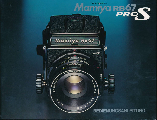
Mamiya RB 67 Pro S System User manual
User manual for Mamiya RB 67 Pro S System. 59 pages in English. Read the original PDF, download or print a copy without registration.
59 pagesEnglish10.2 MB PDF

Loading your manual…Open PDF directly
Document details
- Brand
- Mamiya
- Model / document
- Mamiya RB 67 Pro S System
- Document type
- User manual
- Language
- English
- Pages
- 59
- File size
- 10.2 MB
- Category
- Film cameras
- Document date
- Not specified in catalog
Search available document text
Find a term, then jump to its page in the original PDF. Image-only pages may not be searchable; check the PDF for exact wording and diagrams.
Page 3 · Read text
CONTENTS
Congratulationson your wise decision         Specifications                                     1
                                             Features                                          2to purchasethis MamiyaR867Camera!                                    Namesof Partsand Outlineof OperatingMethod        6
                                            OperatingInstructions...........                      1 1
  Perusingthis manualbefore attemptingto           Attachingand removingthe lens ........              1 2
use the R867 will assist in correct camera           Shuttercocking/Shutterreleasebutton              1 3
operationand will minimize the possibility          Operatingthe focusinghood                       1 4
of malfunctions.                                   Horizontaland verticalpictureformat
 The Mamiya RB67 is one member of a            selectiveoperation                           15
unique "camera family" developed by the           Attachingand detachingthe roll film holder             .. 16
Mamiya Camera Company, a recognized          Loadingand advancingthe roll film .........          18
world leader in large-formatphotography.           Multipleexposurephotography............           21
The RB67 takes its place alongside the            Settingthe shutterspeed and the aperture/Time
famous Mamiya C Professionaland the           operation.....:...........                      22
Mamiya Press Cameras.                        Focusingknob fixingoperation/Distancescale      23
  Versatilityof the MamiyaR867,embodying           Depth-of-field/Usinga triPod                  24
fine performanceand various capabilities,         Close-upphotography...........                25
results in a large format camera that meets           Close-upphotographywith auto extensiontubes .......'26
and satisfies all requirements of the ad-           FlashphotograPhY                        28
vanced amateuras well as the professional           Mirror-upphotography(lndependentmirrorrelease).... 29
photographer,offering the means of pro-          Lens hood/CarrYingstraP                     30
ducing top-grade pictures in alt fields in-          Changingthe magnifier/Focusinghood                   JZ
cluding  general commercial, industrial,         Changingthe focusingscreen/Revolvingadapter ........33
scientific,and news photography. lts inter-           Lock systemof the cameraback(attachingsystem)   36
locking with many Mamiya Press camera         MamiyaR867 oPerationdiagram               3B
accessories further widens the range of           Specialpointersin usingthe MamiyaR867 Pro-S     39
the R867'sphotographicapplication.             Lenses                                    40
                                             Accessories                               47

                          www.butkus.us
                                                 -.---.------/
View original page 3Page 4 · Read text
g1 Specificationsof MamiyaRB67 Pro-S


 CameraBody                      Maximum extension 46mm. With focusing      Film advance:
                                          knob fixing device.                           One-stroke lever film advance (After 70o
Type:                                           Shutter and mirror cocking:                       winding, can be wound in several short,
  6 x 7cm  lens-shutter type,  single-lens       Single-action (75") cocking by lever on         definite strokes ).
  reflex camera                            camera body side.                           Automatic double-exposure prevention.
Lens mount:                                   Others:                                          Film wind stop automatic release.
  Bayonet mount (with safety lock ring)          Accessory shoe is provided.                     Multiple exposure is obtainable optionally.
Viewfinder:                                      Shutter release button can be locked to       Film counter:
  Horizontal format index mark interlocks       prevent releasing the shutteraccidentally.       Automatic resetting type; Red index mark  with revolution of revolving adapter (Ver-
  tical format based on fixing index line on     Standard Lenses:                      disappearsupon completionof film wind-                                                                                                                                                                                                                                           i n g .  focusing screen.)                                       Mamiya Sekor 90mm f/3.8 with lens hood      Provided with dark slide dislocation pre-
Focusing hood:                                        Mamiya Sekor 127mm f/3.8 with lens hood       ventive device and memo clip.  Single-actionopening and closing, with
  mounting lock.                                       Filter screw diameter: 77mm             Dimensions:
  lnterchangeable.                             Aperture: Full automatic diaphragm (with
  Finder magnificationis 2.5X.                    depth-of-field preview lever). f/3.8 to 32     (Camera body with roll film holdefl
  Magnifieris also interchangeable.              (with  click-stop  for  half-step aperture      Height:  5-21/32in. {144mml                                                                                           Width:   4-3/32in.  (104mm)Focusing screen:                                    settingsl.
  With fresnel lens   Interchangeable          With  mirror-up .photographing feature      Length:  8-31/32in. (228mml
Revolving adapter (exclusively for Pro-S):         (independent mirror release) device.                     (with 90mm !/3 8 lens)                                                                                                            8-17/32i6. Ql7mm)  Vertical and horizontal positions revolving      Shutter:                                                                                                          (with 127mmf/3.8 lens)  up to  full 90o rotary system, with format       Seiko # 1 shutter
  indication interlocking mechanism.             1 to 1/400 second and T (Time)             Weight:
  By R-lock system, interchangeable with      Flash synchronization:
  other adapters.                         M-X full synchronization                  Camera body with revolving adapter and                                                                                        focusing hood ......3 lbs.,3-2/16 oz. (14509)
  By G-lock system, of revolving adapter,     Pro-S 120 Roll Film Holder         Pro-S roll film holder ....15-14/16oz. (4509)  G-lock-type film holders are attachable.
Focusing:                                      Film used:                          90mm f/3.8 lens .....28-6/16oz. (8059)
  Bellows  extension  system  with  rack      120 roll film 10 exposures; 6 x 7cm format     127mm f/3.8 lens ..... 26-7/16 oz.  (7509)
  pinions.                                       Actual negative size:
                                           56 x 68.4mm


                                                  -t*:u**:*n,.              .:::^    .                                                                                                                                                                                     ... :. u*i:,                                         .  *,.  .*-  "   ii
View original page 4Page 5 · Read text
Featuresof MamiyaRB67 Pro-S


  The Mamiya RB67 Pro-S is a unique, high-grade'      1. Rational6 x 7cm format
6 x 7cm lens-shuttertype, single-lens reflex camera       Sincethe 6 x 7cmformatcoversan area4.5 timesthe 35mm
developed to offer excellent picture quality and easy       format, excellent picture quality is obtainable. Especially, it demon-                                                                           strates superb results in color photography. The ratio between thehandlinQ. Mamiya feels confident that the extensive                                                                        length and width of 6 x 7cm formats is almost the same as that of
versatilityand capabilitiesof the Pro-S will meet and                                                                          large photographic paper, permitting economical enlargements
satisfythe requirementsof all photographers.                  without cropping.
                                                       When designing a magazine layout, a sufficient blank space is
                                                                    reserved for headlines and explanatory notes,'so that the entire
                                                                           picture format can be fully utilized.
                                                                    2. Single-lensreflex camera offering a bright, large finder
                                                   image
                                                           since parallax-freefocusingin the outstandingfeatureof the
                                                                  single-lensreflex camera,speedy camera operation is possible
                                                             throughbrilliant,precise6 x 7cm picturecomposition'
                                                                            3.  Excellent Mamiya Sekor lenses
                                                      Mamiyasekor lensesboastexcellentimage renditionand color
                                                              balance.Varioustypesrangingfrom wide-anglelensesto telepho-
                                                                    tos lensesare available.
                                                                                                                                                               lI
                             www.butkus.us
                                                                                                                                            l
                                                                                                                                                                                                                                                                                            "*l l !S **   ii ii*tiL* ii&   t  *#
View original page 5Page 6 · Read text
These lenses are rationally grouped  in series, whereby those       6. Vertical or horizontal picture format quickly changed
exactly adaptable to one's particular photographing objectives are      over with the revolving adapter
optionally selectable with ease.                                    A revolving adapter is provided as a standard outfit, whereby the
4. Lens-shutter system  suitable  for  electronic  flash        vertical or horizontal picture format is promptly selected by turning
photography                                                          the camera body back by 90o,without changing the camera position.
  By adoptingthe lens-shuttersystem,electronicflashis synchro-       This is especially convenient when the camera is mounted on a
                                                                                tripod.nized with all shutter speeds, making it possible to produce highty
impressive photographs.                                              7. Finder format index interlocked with revolving adapter
5. Double-exposure  prevention  and   multiexposure      Whenthe revolvingadapteris turnedup to 90',horizontalformat
                                                             pictureindexred linesappear(or disappear),presentingproperdevices
                                                             picturecomposition.  An interlocking device for double-exposure prevention is incor-
porated in the Pro-S roll film holder. Since this device is interlocked       8. Excellentfilm flatnessensured by Pro-S roll film holder
with the Pro-S body mechanism, the shutter cannot be released                                                                      Various tests have been applied to the Pro-S roll film holder to
unless the film is advanced. Also, film advance for the next expo-                                                                               stabilize film flatness. As a result, film flatness has been further
sure is impossible unless the shutter is released.                                                                   improved.
  When the shutter is released, the film wind-stop is automatically
released.                                                            9. Camera back adapter changeable according to photo-
                                                          graphing objectives  Multiple exposure photography is available simply by switching a
lever.                                                          By changing the back adapter, depending on your photographic
                                                                          objective,the range of film applications can be widenedtoinclude
                                                              120 and 22O roll films,dry plates,cut films,


                                                 " "  .l    -   -  . -i?  \,-S*.:       ;                                                   ,r*iga::.   ,t:  .r.*.'         3                                                                                                                                                  '-.--'*tii'i.                          --    4rtu-"a-.                            .,!
View original page 6Page 7 · Read text
and 70mm film.                                                   on the photographing objectives, a checker, a rangefinder spot, a
  The film holders and back adapters are very easily exchanged.         microprism, and a cross-hair can be selected at your option.
                                                            12. Excellent heat- and cold-resistantcapacity10. Unique mirror shockless mechanism
                                                           Camera component parts are capable of demonstrating their
   By'adopting a unique centrifuged friction governor system, the                                                                        functions within a wide temperature range from approximately 120"F
mirror functions smoothly without sensing shocks.  Mirror shock,                                                                                 to  - 50F (50"C to  - 20'C).
constituting the most important problem involved in large, single-                                                              The lens-shutter maintains accurate function, even in severe cold,
lens reflex cameras, has been solved.                                                              and shutter speed deviation is negligible. lts resistivity to coldness
11. Large variety of finders                                                      is superb.
  A big selection of finders conforming to your photographic ob-         Although the camera operating unit grows sluggish at or below
jective are available.                                                15" F (- 10'C), it is sufficientlycapable or operating the camera until
  They include a CdS finder (appropriate exposure obtainable with       the temperature drops to approximately - 50" F (- 20'C).
Through-the-lens measuringsystem),a Prism finder (subjects can be      13. Mirror-up photography (independent mirror release)
seen as an erect image), a CdS prism finder (former two types  of      possible
 finders are combined),a Magnifyinghood (easilyvisible and bright),                                                       When sharp pictures are demanded, the mirror-up mechantsm
 a Dual magnifying hood (performsprecision focusing by speedily                                                                    plays a big role. When taking a picture unhurriedlywith the camera
 changing the magnifier of high magnification), and a Universal                                                            mounted on a tripod, or when photographing at slow shutter speeds
 sportsfinder (permits focusing on the focusing screen after it has                                                                            or using a telephoto lens, the mirror-up operation merit is highly
been installed).                                                                                   effective.
  The focusing screens are also easily exchangeable. Depending


                            www.butkus.us


                              ,,.it!a!,r{-,.:.f.,. ::."r:r*h,l;i;r                                                                   **s",',J.i,r--        4               -;:.:*d*ir:-a**il;i'i:X*o,-.,:Ee;*r**rl-',,,-..                                      rl*b:';...-  -  -,.{is'i*"          ..-,-i  .r.,,r
View original page 7Page 8 · Read text
14. Close-up photography through  full use of bellows      17. Dark slide lock for safety while carrying
    characteristic f eatures                                   A dark slide lock is provided for the Pro-S roll fitm holder so that
  Since the bellows can be extended up to 46mm, photographing       the dark slide will not slip off while carrying the hotder detached
small subjects in the frame full size is possible. when auto exten-       from the camera body.
sion tubes are used, the subject can be further enlarged. When a      18. Accessory shoe
standard lens is employed, life-size (1:1) or larger picturescan be                                               Anaccessoryshoeis providedfor convenientusewhenmountingphotographed.
                                                                      the clip-on-typeflash unit.
15. Single-actionfocusing hood                                                           19. Unique safety devices
  Available as a standard outfit is a collapsible focusing hood,                                                                     Various safety devices eliminate possible photographic failures.
which can be opened and closed by single action, and which can
                                                             20. Gomplete set of accessoriesbe shieldedfrom extraneouslight by raisingthe magnifier. Depend-
ing on diopter of your eyes, the magnifiers are interchangeable. A          Availability of a complete set of various accessories further aug-
double-lock mechanism prevents the focusing hood from acciden-      ments photographic possibilitiesand camera versatility.
tally slipping off.
16. Focusing knob fixing device
  A focusing knob fixing device is provided so that the focusing
knob will not be moved inadvertenily during close-up photography,
taking snapshots, fixed focus photography, or using a telephoto
lens.


                                r  ."*i':..      **.f.          .                ,l*c$6i@.;.                                 ,  rrr-. \scbs^                                                                        ,';*rlq*;";,'r*gfAil*iil:"                                                               i*,:-^'*;.-         -.ru'..*gJa*o*tO-"                                        s,R-..       *-,.t
View original page 8Page 15 · Read text
Attachingand Removingthe lens

o Attaching the Lens

        L
                                                E t t . r r r r - - . r ; : j
                                                 56

After  cocking  the  camera  body  mirror     Gocking the Lens Shutter                        Attaching the Lens
and the lens shutter, mount the lens on the       ,1. Remove the rear cap of the lens.               1. Turn the bayonet ring (11)counterclock-
camera body.                                      2. Cock the lens shutter. Firmly turn the      wise, and align the red dot on the bayonet
                                                shutter cocking pins (56) with your fingers.      ring with the triangular mark at the center.
Cocking the Mirror of Camera body                to the red dots (A) of the cocking position       2. Mount the lens, keeping the triangular
1. Remove the   f ront body cap from the     marks. Now the shutter blades are open.     mark aligned with the lens mounting mark
camera body.                        When removing your fingers from the pins,      (10);then firmly twist the bayonet ring clock-
2. Be sure that the mirror (3) is in the cock-      the cocking pins will turn back to the green      wise. Now, the camera and lens have been
ed, down  position in the camera body,      dots (B).                                            set.
shieldingthe camera film plane from expo-         *   lf the cocking pins are not fully turned to
sure to light.                                   the red dots (A), the shutter will not  be
 lf the mirror  is up, cock the mirror by     completely cocked.
fully pushingdown the shutter cocking lever        *  After removing the lens from the camera
(1)toward the front of the camera.              body, the shutter is always cocked.

                                               when attaching or removingNOTE:   lf the camera is placed with its back facing downwardwww.butkus.us
 lhe lens,without mountingthe rearbody cap or the film holder,the coupling mechanismmay
be damaged. Always pay attentionto this caution'
                                             1 2
View original page 15Page 16 · Read text
ShutterCocking    ShutterReleaseButton
                                                                        o Disengaging the release lock of the o Removing the Lens
                                                                                     shutter release button


Remove the  lens  while the  mirror and     Press down  the  shutter cocking  lever      This  saf ety mechanism  is designed  to
the shutter are cocked.                             (1). The shutter in the mounted lens and the      prevent accidental release of the shutter
Turn the bayonet  ring (11) counterclock-     mirror in the camera body are cocked simul-      while carrying the camera in its case.
wise, aligning its red dot with the  lens     taneously. The lever will return to  its ori-     When the shutter release lock ring (6) is
mounting mark (10)on the body, and remove      ginal position by self-action.                    turned and the index mark is aligned with
the lens.                                                      * When shutter cocking is not completed,       the white dot (A) on the body, the shutter
 *   lf the mirror and the shutter are  not      the shutter cocking lever will not return to       release button (7) can be pressed.
cocked in this instance,the lens cannot be        its original position.                      When the index mark is aligned with the
removed, because turning the bayonet ring        * Once the shutter is cocked, the cocking      orange dot (B), the shutter release button
will be intercepted by action of the safety      lever will not move until the shutter is re-      cannot be pressed.
interlock mechanism.                         leased by pushing the shutter release button.      o  Releasing the shutter
                                             Therefore, when the cocking lever will not     When  the   shutter  release  button   is
                                        move, you know the shutter is cocked.           pressed, the mirror is pushed up and the
                                                                                                 shutter is released.
                                                                                                                                    *   lf the mirror is not cocked, the shutter
                                                                                            release button cannot be depressed.
                                                                                                                                    * The socket inside the shutter release
                                                                                                button is threaded so that a cable  release
                                                                                                       or a self-timer can be easily attached.
View original page 16Page 18 · Read text
c    changingthe PictureFormatto Horizontaror vertical
    o Operating the revolving adapter       o Vieyyfieldof horizontal or vertical format


1


    When the horizontal format mark  of the
     revolving adapter is facing upward, a hori-
     zontal format  will  result. To compose a
     vertical  photograph,  turn  the  revolving
     adapter clockwise until it stops. To change
     from vertical to horizontal,turn the revolving
     adapter cou nterclockwise.
      In either case, be sure to turn the adapter
     a  full 90o until  it clicks and stops.   lf the
     adapter  is stopped midway, the  shutter
     release button cannot be pressed.

       * Do NOT turn the revolving adapter while
     the shutter release button is being pressed.      Horizontal picture format                             Vertical picture format
     Especially, when a cable release or a self-    When the revolving adapter is positioned at    When the revolving adapter is positioned in
     timer is used, and adjustment of the release      the horizontal format, red lines appear on      the vertical format, the red lines disappear.
      tip is improper, the shutter release button     the ground glass focusing screen to indicate     Compose the picture within the broken lines
      will remain depressed after the shutter is     a horizontal picture format. Compose the      on both sides.
     released. Always pay attention to this fact.      picture within the red lines.
                                                     1 5
View original page 18Page 19 · Read text
c   Attachingand Detachingthe Roll Film Holder

 o Removing the rear body cap          o Attaching the roll film holder


 By moving the slide locks (29) on both sides      1. Before attaching the holder, confirm that       2. Attach the roll film holder and slide both
 fully to the left, the cap can be removed.        the upper and lower side slide locks (29)      slide locks firmly in the directionof the arrow
                                               are on the left end of the indented portion      mark.
 * Never push the light baffle (26) on the     when viewed from behind the camera body.
 camera back after removing the reat body                                                                           *   lf the slide lock of the revolving adapter
 cap.   lt the light baffle is pushed by force,    NOTE:                                                     is not pushed fully in ot out, the shutter will
 it will cause light leakage or a malfunction.     Should  either  slide lock be moved  to the       not be  released because  of the shutter
                                                          right while nothing is attached to the revolv-       locking safety device. Always operate the
                                                    ing adapter, the slide lock release lever (31)      slide lock securelY.
                                                                will engage and the slide lock will not move'
                                                                                          lf this happens, press the release lever (31)         *   lf closing the lower slide lock is neglect-
                                           and return the slide lock to the open posi-       ed, the safety device of the Pro-S holder
                                                          tion.                                                        will prevent the dark slide from being re-
                                                                                  moved.
                                                                                                                                     *   lf the dark slide is completely inserted,
                                                                                                        or  if the film is not loaded, the shutter re-
                                                                                            lease button cannot be pressed, leading to                             www.butkus.us                                                                                                      picture-taking failure.

                                                  1 6
View original page 19Page 20 · Read text
o Detachingthe roll film holder


1.   Insert         a dark                slide                         in the                                 roll                                 film                                  holder.                                    NOTE:                                               When desiring to releasethe shutter     white            linesTwo              on the                       side                               the                                of                                 holder     Since                                                    a  coupling  device  for
indicatethe positionof the insertingslit.       double-exposure prevention  is       without loading the film.
2. Remove the roll film holder by sliding    adapted for the Pro-S roll film
both slide locks (29) in the opposite direc-     holder, the shutter cannot be            In this instance,the shutter can be released by
tion to the arrow mark on the slide lock.        released if the film is not loaded.           sliding the multiexposure lever of the roll film
                                                                                   holder to the front, and by setting the shutter
 *   lf the dark slide is not inserted,the slide                                         cocking lever and pulling out the dark slide.
lock will be locked by the safety device,                                                 ,F When the dark slide is.completely inserted,
and the roll film holder cannot be detached.                                             the shutter release button cannot be pressed.
 * When a dark slide is completelyinserted,                                          Therefore,either remove the dark slide or draw
the slide lock release lever (31)is automa-                                                                               it outward to a position where the entire trian-
tically disengaged,and the slide locks can                                             gular hole in the top center of the dark slide
be slid without pressingthe release levers.                                   becomes visible.
                                                                                              ,F Either operation of the multiexposure lever
                                                                                             or the shuttercocking can be initiallyconducted.


                                                  1 7
View original page 20Page 21 · Read text
O Loadingand Advancing the Roll Film

o Loading the film


                                          43                                                                                                                                                                                                                                                                                                 I

1. Open the back cover by pulling out the      2. While pressingthe left side spool release      3. Pull out the leader paper and insert the
back cover latch,while slightlypressingthe     pin (43), insert a new roll of film on the f ilm        tip into the groove of the take-up spool.
back cover. Remove the film insert from     spool stud.
the holder.                              Load the film so that the leader paper can         *  Positionthe f ilm so that the leader paper
                                        be pulled out along the arrow of the leader     winds evenly between the spool flanges;
 * When loading and unloading film, avoid     paper guide mark (36). In this way, the black      otherwisethe film may be taken up unevenly,
 direct sunlight. Choose a location in the     side of the leader paper will appear on the      causingtrouble.
shade.                                      outside.
 *  Regardlessof whetherthe roll f ilm holder
 is attachedto or detached from the camera        *   lf the black side does not appear on the
 body, loadrng and unloading the  roll film     outside, reload the film, reversing the film
 can be conductedin the same manner.         position.
 * Use 120 roll film with the 120 roll film
 holder, and 220 roll film with the 220 roll
 film holder.

                             www.butkus.us

                                                  1 8
View original page 21Page 22 · Read text
o Aligning the starting mark            o Attaching the film insert             o Film winding for first exposure


Move the film advance lever gently, until       1. Put the insert into the cassette, aligning    By winding the film advance lever untif it
the starting mark (arrow) of the leader paper      the top side of the insert with the white dot      stops,the figure "1" will appear in the expo-
aligns with the starting mark of the holder.       (A) of the cassette.                            sure counter (39), the red mark indicating
The film advance lever can be moved in          *   lf the film insert is attached in reverse,     incompletefilm winding will disappear,and
several short, definite strokes.                   the back cover cannot be closed.               the film will be positioned for the first expo-
                                                      2. Close the back cover and fully push in     su re
 *   lf the leader paper is pulled too far, the       the back cover latch while pressing the
film may become fogged. Be careful not to      back cover.                                                  *  Unless film winding from S to 1 in the
go beyond the starting mark (arrow).                                                    exposure counter is completed, the shutter
                                  NOTES                                    cannot be released.
                                                         1. The outer cassette of the Pro-S roll film
                                                   holder can be used  for both 120 and 220
                                                           film inserts.
                                                         2. The film insert of the Pro-S roll film holder
                                              cannot be attached  to the outer cassette
                                                         of the former RB67 roll film holder.


                                                   1 9
View original page 22Page 23 · Read text
o Film advancing                                                       o Film advancing and shutter cocking

                                                  {< Wind the film advance lever in a slow,
                                           steady manner to avoid film winding prob-
                                           lems.
                                                                  * Although the film advance lever cannot
                                         be reversed until it is wound up to the ini-
                                                              tial 70" winding, it can be moved in several
                                                   short, definite strokes thereafter.
                                                                  * The film wind-stop releaselever provided
     Exposed                    completed               for the Pro-S roll film holder is to be used
                                     ( Befo 't ex posure)      when the holder is used for the M am iya
                                             Universal Press, or when desiring to wind
1. Draw out the dark slide and release the     up to the film end while unexposed film
 shutter. When the shutter is released, the     remains in the holder.
 red mark appears in the exposure counter,
 indicatingthat the film is exposed.                3. When you finishexposingthe full number
 2. Simultaneouslywhen the shutter is re-       of exposures, the shutter release button
 leased, the film wind-stop mechanism is     cannot be depressed and the film advance
automaticallydisengaged, and the film can      lever will be freed. Then wind the film com-      Eitherfilm advancing or shuttercocking can
be advancedfor the next frame. When film      pletely to the end of the leader paper.             initially conducted. However, the recom-
                                                                        mended sequence of these steps to be is advanced one full frame, the figure in the
exposure counter is advanced, and the red     o Unloadingthe film                       customarilyobserved is: (1)film advancing,
                                                                                          (21 shutter cocking, and finally (3) shuttermark disappears.                                 1. Open the back cover of the holder and                                                                                                     re leasing.                                       remove the film insert. Press the right side
 * Unless the exposed film frame is ad-      spool release pin (43),remove the full spool,
vanced, shutter releasing is prevented by      then wrap and seal the film to protect  it
the coupling device for double-exposure    from loosening.
prevention.                                         2. Move the empty spool to the take-up
 *  Shiftingto multipleexposure photography     side. The insert is ready for reloading.
 is possible. Refer to the next page.                  * The exposure counter automaticallyre-
 * Even though film advance is completed,     sets to S (start) as soon as the back cover
the shutter cannot be released if return of        is opened.
the film advance lever is hindered by your       :r<When the exposure counter shows other
fingers or by another object.                   than S, a film is loaded in the holder.
                           www.butkus.us

                                        20
View original page 23Page 24 · Read text
o  MultipleExposurePhotography

                                             o When desiring to wind up to the end of film while unexposed film
                                            remains in the holder.


                                                                     When the film advance lever is continuously
                                                                                  wound, with the film wind-stop release lever
                                                                                                  (42)pushed to the left, the film can be reeled
                                                                                   up completely to its end, even though pic-
                                                                                                     ture taking is  still in progress and a film
                                                                                      remains u nexposed.


                                             o Storing the dark slide


                                                                                        While progressing with photography, the
                                                                                         dark slide of the roll film holder can be
When the multiexposure lever of the  roll                                                     stored by inserting it into the camera body
film holder is moved forward, the coupling                                                      side.
pin for double-exposure prevention is dis-
engaged,and whenever the shutter cocking
lever is set, shutter releasing can be  re-
peated without limit.
                                             o Memo clip * The multiexposurelever can be changed
over before or after shutter cocking, and
also before or after shutter releasing for the
first multiple exposure photograph.
 * When taking multiple exposure pictures
is finished, never fail to return the multiex-                                             The clip on the back cover can be used for
posure lever to its original position; other-                                                   holding the cover of a film box or a slip of
                                                                                      paper to record information.wise, failure in taking subsequent multiple
exposure pictures will occur.


                                              21
View original page 24Page 26 · Read text
O Focusingand FocusingKnob Fixing        o DistanceScale

o Focusing                          o Focusing knob fixing


When the shutter is cocked, the mirror is      After adjusting the focus, turn the focusing     Distance from the film plane to the subject
cocked simultaneously, and an image  is     knob fixing lever (18)forward and appropri-     can be determined by the distance scale
visible on the ground glass of the focusing      ately clamp it, whereby the focusing mech-       (5).
screen. By turning either the  left or right     anism is secured.                          Curves on the distance scale are repre-
focusing knob, adjust the focus and com-                                                 sented in a different color for each lens.
pose the picture.                                           *  Deviation in focusing can be prevented     The figure on the distance graduation (4)
                                                         in this manner, when continuously taking     which meets the curve for the lens used
                                                  pictures, taking snapshots with wide-angle      after focusing reveals the distance to the
                                              lenses, close-up photographs, and using     su bject.
                                             telephoto lenses.                            For example, if the distance graduation and
                                                                                                 the curve are as shown in the photo after
                                                                                           focusing with the 127mm lens, you can con-
                                                                                                      firm that distance to the subject is 5ft. (1.5m)
                                                                                       by reading the graduation aligned with the
                                                                                    orange curve.


                                         23
View original page 26Page 27 · Read text
n\.4  Depth-of-field                           Using a Tripod

o Viewing on the focusing screen       o Using the depth-of-field scale


                                                                              32 33            4 7  48

 1. Set the desired aperture by turning the       1. Turn the distance scale lever (48) and      For maximum picture sharpness the use of
 aperture scale  ring (51); then adjust the      align the figure representing the focused      a sturdy tripod is recommended. Insert the
 focus.                                        distance with the center index mark on the       tripod screw into the tripod socket (32) at
 2. Depress the depth-of-field preview lever     depth of field scale (53).                        the bottom of the camera.
 (47)and the depth-of-field can be observed       2. The two distances (on both sides of the     When a tripod with a 3/8 inch tripod screw
 on the ground glass focusing screen.           center index mark) opposite the same fig-        is used, remove the inner socket by turning
 When removing your finger, the lever  will      ures as the actual lens aperture on the      the tripod socket counterclockwise with a
 return to  its original position and the lens      depth-of-field scale are the near and  lar      coin or similar disk inserted in the slots of
 aperturewill fully reopen.                          limits of depth for a given distance and lens      the socket. The standard tripod has a 1/4
                                                  aperture.                                       inch tripod screw and can be used for this
                                             For example, when photographing a subject     camera in conjunction with the inner tripod
                                           10 feet away with the 127mm lens  at an       socket.
                                                aperture of tl 16, obiects from about 8 to 13     o Tripod Mounting Base                                                   feet will be in focus.
                                                                                 The tripod mounting base (33) at the bottom
                                                                                                              of the camera is for attaching a quick shoe.
                             www.butkus.us               head,lf you thekeepcameraa quickcanshoebe quicklyon yourand tripodeasily
                                                                                mounted on  it.

                                         24
View original page 27Page 28 · Read text
CI Close-up Photography
                                                      o Maximum close-up photography tableo Exposurecompensation for close-up photography                                                                             (with bellows fully extended)
                                                                                                       Lens -to-subject                                                                                                  Le                                                                                                                  distance             Magnif  ication            Subject size
                                                                      50mmf/4.5               t"4i  ( 4.9cm)        0 . 8 8       z%"x  3xr' ( 6.3x 7.7m)

                                                                                                    6 5 m mf / 4 . 5              3'Xr' ( 8.5cm)       0 . 7 1       S%'x 3X, ( 7.9x 9.7cm)

                                                                     90mmf/3.8          7%' (20.len)       0 .5 l          tX{ x 5%r"(tt.ox 13.4cm)

                                                                                                  l27nn  f /3.8              r' 5)6"(43.3cm)     0 . 3 6       a26"x 7K;05.5x18.9cm)

                                                                                                                                                                                                                                                        l 8 0 m mf / 4 . 5          2' |txr" ( 8a.70r)      0 . 2 6       g%' x l0%' (21.9x26 .7crn)

                                                                        250mmf./4.5         5'3X6"( l60cm )        0. l8                     l' x  l' 2%' (30.4x37.2an)
                                                                        360mmf./6.3              tt' t%" ( 3locm;       0 . 1 3          r' s%;xt' exi (lr.ax 53.4cm)

                                                                        The lens-to-subject distance represents the distance of the subject from the front
                                                                        edge of the lens barrel.

When the lens is extended for close-up pho-       2. Compensate the exposure by changing        * When using the 50mm and 65mm lenses
tography,and distance between the lens and      either the shutter speed or the aperture.        cfoser than 3 %tt (1 meter), it is necessary
the   f ilm plane increases beyond normal,    When the exposure compensationvalue is       to use a lens aperture of f/16 or smaller to
image brightness on the film plane de-      + 1, open the aperture one stop, or slow the      obtain satisfactory lens performance.
creases, requiring an increase in exposure.      shutter speed 1 step. For 0.5 step compen-         * Graduations on the upper side of the
To adjust the exposure,referto the exposure      sation, use the  half-stop aperture scale      distance scale represents the bellows ex-
compensation scale on the camera body.         setting s.                                      tension values (mm).
1. After adjusting focus on the subject, read      For example, if your exposure meter shows      This scale is used to obtain exposure com-
the exposure compensationvalue obtained     an exposure setting of (1/60 sec. at t/16), it     pensation values for close-up photography
on the exposure compensationscale.          must be adjusted in the case of the + 1      with extension tubes.  (Refer to  the  next
For example, assume that focus was ad-     compensation value to (1/30 sec. at t/16) or      page.)
justed with the 127mm lens and the result      (1/60 sec. ot t/111.
was as shown in the photo.
Seek the same pattern in the bottom column         * When  using the CdS   f inder for  the
as the pattern where side panel lines meet     Mamiya RB, exposure need not be com-
the 127mm lens scale. The numerical value     pensated, since the meter reads actual
of that pattern (+ 1 in this case) is the expo-     exposure directly.
sure compensationvalue.

                                         25
View original page 28Page 32 · Read text
Mirror-upPhotography(lndependentMirror Release)O


                                                                                            o Photographing
                                                                                                             1. On pressing the shutter release button,
                                                                                              the mirror and the light baffle will snap up,
                                                                                                but the shutter will not be released.
                                                                                                             2. Release  the  shutter  with  the  cable
                                                                                               release. (When you do not have a cable
                                                                                               release, simply return the mirror release
                                                                                         operating knob to the original position to                                      o
                                                                                           release the shutter. )
                                                                                                          3. By pulling out the knob and turning it
                                                                                        counterclockwise,the mirror-up mechanism
                                                                                 can be disengaged.
                                                                                                                                   *  Even when  picture-taking  is switched
                                                                                                          to mirror-up photography,the mirror is set
                                                                                                          at each shutter cocking. Accordingly, it  is
                                                                                          possible to confirm the image on the finder
                                                                                     screen prior to taking each picture.
 In mirror-up photography,previously release     screw socket in the knob center.              #  For this type of photography, an ideal
the mirror and operate only the lens shutter       3. By fully pressing down the shutter cock-     forked mirror-up cable release is available
 at the moment of taking the photograph.         ing lever, cock the shutter and the mirror.      as an optional accessory.
This mirror-up photography is recommended          * The sequence of foregoing procedures    NOTE:
When a tripod is employed and the shutter       1, 2, and 3 can be optionally altered.           Unless  the mirror release operating knob
 is released at slow speed, when  taking                                                                       is returned, the camera  will remain set for
close-up photos, or when using a telephoto                                                     mirror-up photography.  In this case, the
lens, where avoidance of even q negligible                                                                film  will not be exposed even when  the
shock  is desired, or when curtailment of                                                         shutter release button is pressed.
even a negligible time lag between pres -
sing  the shutter release button and the
shutter opening is desired.

o Preparations
1. Pull out the independent mirror release
operating knob (50) and turn it clockwise,
and align the red dot on the knob with the
MIRROR UP indicationdot.
2. Screw a cable release into the female
View original page 32Page 33 · Read text
n\^a Lens Hood                                                     n\^a CarryingStrap

                                                o Attaching


    For 127mm,180mm                          Folded lens hood
   and 250mm lenses

   This lens hood can be used commonly for the 90mm,       While holding both sides of the         Note:
 127mm,180mm, and 250mm lenses.                              strap attaching metal, slide the        Always attach and use the straP
                                                                   attach ing  m etal  toward  the        so that it and the straP attaching
 1.  Screw the attachment ring into the front of the lens       hanging direction, after fitting        metal are straight.
mou nt                                                  and pressing the round hole on      When changing the straP hang-
 2.  Pull the folded rubber hood straightout, using it as the       the metal back side to the lug         ing d irection, alwaYs reattach
 hood f or th e 127mm,180mm,and 250mm lenses                                                                             for strap on the camera body.           the strap.
 3.  For the 90mm lens, fold the hood back halfway.                                                                          *   lf the strap attaching metal is
  To fold the hood, pull it straightout, place the hood on a                                          connected  to  the  accessorY
 flat surface, and push down from the top to easily fold the                                        shoe side in reverse, detaching
 lens hood                                                                                                                    will be difflcult.
   You can also leave the hood on the lens for portabilityby
 pushing back and turning out the hood while it is attached
 to the lens
   A filter can be screwed in between the lens and the hood,
 or in front of the lens hood.


                             www.butkus.us

                                          30
View original page 33Related documents and language editions

From the M. Butkus archive. Original publisher and archive notices are retained.
Check the model and edition against your equipment.
PDF verified 2026-10-10.