Film cameras
Metz Mecamat 45 / 46 User manual
User manual for Metz Mecamat 45 / 46. 21 pages in German, Spanish. Read the original PDF, download or print a copy without registration.
21 pagesGerman, Spanish6.9 MB PDF

Loading your manual…Open PDF directly
Document details
- Brand
- Metz
- Model / document
- Metz Mecamat 45 / 46
- Document type
- User manual
- Language
- German, Spanish
- Pages
- 21
- File size
- 6.9 MB
- Category
- Film cameras
- Document date
- Not specified in catalog
Search available document text
Find a term, then jump to its page in the original PDF. Image-only pages may not be searchable; check the PDF for exact wording and diagrams.
Page 2 · Read text
Mffionen tleE&eEE bi nhidenen ftnden,
    O METZ flFT.AITUOEII
      o METZ UIfrVBECHEENXET                                                                                         . *,*"**:'
      o      ilm ilEcABrnzilfizaEBiUE
    O MEIZ FABBFEET{SEIICEEAIE
    O METZ AUBIIAT(UCEII
                                        IIIECABLITZ
                                          IrlECAttlAT 45 -116

                                                                                OPERATING INSTRUCTIONS
                                                                                 INSTRUCCIONES DEL MANEJO
             MeE - imner erctq l(hsae24'          APPARATEWERKEwINH PAUL METZ B51O FURTH/BAY
                                            Printed in Germany 78347 0221/18509donated to www.butkus.us
View original page 2Page 6 · Read text
tl
 1.   Operating            elements                                                                                                    Fig.                                                                                    mode.                                                                                                                    control side                                                                                         "C* "Manual Fig.       nA,, Rear and                    front view                                                                             mode                                                                                                                          indicator                                                                                         Operating                                  @
O sensor                              @ Setting dial for power ratios or flash durations@ Knurled nut for horizontal alignment of Mecamat                                @ Film speed setting knob@ Sync-cord connection                                @ lndex mark for film speed
@ Knurled nut for securing the foot                    @ Index mark for selected power ratio/flash duration
@ Hot-shoe contact                        @ Distance scale metres/feer@ Visor front plate                                  @ Aperture scale
O Visor slide                            @ Film speed in DIN and ASA@ Connecting plug to Mecablitz                                @ Power ratio scale
@ Operating mode selector                      @ ftasn duration scale@ Flash ready light
@ Ruto check for bounce flashing                                                             Fig. DD( Auto flash ranges in metres and teet
@ Setting screw for vertical adjustment of Mecamat                                                    (ref lector-to-subject distance)
@ Foot with hot-shoe and sync-contact, tilts horizontally and vertically
@ Manual release
Fig. >Bn >Auto mode( control side
@ Coverage angle selector
@ Setting disk lor Mecamat apenures
@ Mecamat aperture selector
@ Aperture scale
@ Distance scale feet/metres
@ Operating mode indicator
@ Film speed setting knob
@ Arrow for setting film speed
@ Film speed scale in DIN/ASA
I
                                       donated to www.butkus.us
View original page 6Page 10 · Read text
Power ratio 1 releases all the energy of the flash unit, setting 1/2 halt of               5. Connec{ing the Mecamat
this etc. The flash recycle times become shorter with decreasing light output            5.1. Fastening. The Mecamat's foot is secured in the accessory shoe of the
enabling exposure sequences with short intervals between flashes.                camera or in the shoe of a bracket by use of the knurled nut (9.The selection of the power ratio is either via the flash duration or by the                                                                                                                   Mecablitz.                                                                                                             to                                                                                                     the                                                                                     Connection                                                                                    is                                                                           for                5.2.                                                 duration                                                           selected                                               flash                                       short                 An appropriatelyrequired           light output.                                                                                                     the                                                                                         Mecamat to the sync cord socket on the Mecablitz.                                                                                                                      of                                                                             Connect                                                                                                plug @                                                                  aperture                                                          the                                             shows                                                disk                                        aperture            movements                                in which the         rapidlreezing
numbei to be set on the camera for the given distance. The power ratio for           Simultaneous  oDeration of the Mecamat and SCA adaptor cable for system
subiects for which the use of the auto mode is not suited (for example,              cameras is not possible with the Mecablitz.
for extremely large subject contrast) is determined with the apedure disk                  ln case the standard 2 m spiral cable of the Mecamat turns out to be too short
from the distance and the desired aperture (depth or field).                                        (e. g. when taking portrait shots), the Mecamat extension cable 60-60 (special
The guide number of the Mecablitz  will change when the wide angle                  accessory) should be used-
diftusor or the tele attachment is mounted  in front of the flash unit.
For this purpose, two additional delta index marks are provided on the                    5.3. Sync connection to the camera. Set the sync lever of your camera to
selector disk.                                                        X or use the X sync connection.
                                                                       Cameras with hot-shoe contact
                                                                                 Synchronization is automatic on inserting the Mecamat in the accessory
                                                                                    shoe. The sync-cord must not be plugged into the connection €) on the
                                                                      Mecamat foot   !
                                                                       Cameras without hot-shoe contact
                                                                                 Synchronization is via a sync-cord. Push aside the slider in the connectign
                                                                                socket using the sync plug and plug the sync cord into the connection @.
                                                                                                   Insert the sync cord plug into a sync connection of the camera.
                                                                          System cameras with special flash functions
                                                                                             Synchronization  is established by connecting theMecamat. Shutter speed and aper-
                                                                                                       ture are both set manually on the camera'


                                      donated to www.butkus.us
View original page 10Page 11 · Read text
5.4. FIArh          ready                      light. Flash                            readiness                                                                                                                                              positions                                                                                                                                              rc                                                                                                                                                                      as                                                                                                                                marked                                                                                                                 rear                                                                                              Mecamat                                                                                                                has                                                    is displayed by illumination of the            The                                                                                                          slide                                                                                                                              of the                                                                                                                        two stop                                              O at the lamp        (19 on            the Mecamal                      and                          on the l/ecablitz.                                                                          and                                                                                    M. Position                                                                                                                                                            is set for                                                                                                                         between                                                                                                                                        and                                                                                                        the                                                                                                                          slide                                                                                                                        distances                                                                                                                                             the                                                                                                                                                    subject                                                           € on
                                                          6 to 0.5 m and position M for distances below 0,5 m for 5.5. Auto check for bounce flashing. A correct exposure test signal (auto           Mecamat from
 check) is given on both the Mecablitz and the Mecamat.                                    oarallax correction.
 6. Auto mode                                                                                      6.4. Coverage angle selection of sensorO. Coverage angle selection is via
                                                                                   the selector(9. The selected coverage angle is then visible in
 Set the Mecablitz to "TTL".                                                          the selector window. The coverage angle can be set to 12 or 25".
 Set the film speed on the Mecamat and on the Mecablitz. please heed when         The aperture setting on the Mecamat and the camera is therefore not
 using the tlash off the camera that no direct light from the reflector enters th€ sen-          affected by the coverage angle selection.
 sor of the Mecamat. This leads to incorrect exposure. please set the Mecamat
 working aperture to the same values as on the camera for normal and tele                      6.5. Setting of the desired Mecamat aperture
exposures. Please check that the exposure subject is within the auto flash
range which applies to the selected aperture. A correction to the Mecamat                6.5.1. Film speed. Set the arrow @ with the knob @ such that  it points
aperture is required via the extension tube for close_ups and macro-expo_               to the film speed in use on the scale €9.
sures. Please take the necessary correction factor from point g (close_uo
and macro photography).                                                                             6.5.2. Mecamat aperture selection. You can select between two ranges
                                                                            each with six worki!9 apertures. Both ranges are marked on the outer edge
6.1. Operating mode selector@. Move this to the left. A white area now                 of the setting disk(9with red and green points. The same colours appear
appears on the display tolhe lett-hand side next to the selector and in the           on the Mecamat aperture selector(!with which you can select the working
operating mode indicator Qq on the auto mode control side.                            aperture range.
                                                                            To set the desired working aperture turn the setting disk@such that the
6.2. Alignments of the sensor @ on the -subject. The setting screw @ is for           coloured index line on the selected range ol the setting disk lines up withvertical tilting. Release the knurled nut @ for horizontal alignment, adjust                 this aperture value on the scale @. Please always heed that the setting disk
the Mecamat, finally retighten the knurled nut.                                                           is exactly positioned. Intermediate settings are not possible. The coloured
                                                                                 index line indicates the maximum distance between the subject and Meca-
!,!,Vggrfo1plate (9) or it siShting.can be withdrawnThe visor (slidecan be@).extendedThe viewingon bothanglesidesls 1io(frontand                  flashblitz {oroperation.the selectedFor theapertureminimumon flash-to-subjectthe scale @ in leetdistance,and metrespleaseforseedirect
corresponds to the 120 coverage angle on the sensor.                                          Fig.                                                                                                             '9., on this manual's cover page.
18
View original page 11Page 13 · Read text
7.2.Film speed setting. Turn the knob @ until the index mark @ is adjacent          The distance is measured between the flash unit and subject. Please take
to the film speed used.                                                                   the guide number from Table 1 and please heed the selected power ratio
                                                                                      (see Point 10).  lf the distance is given in metres then please use the guide
7.3. Selection of the power ratio or flash duration. Seven ratios are                  numbers of the metre system and those ol the feet system for distances in
available. To set these turn the setting dial @. Allow the dial to position
exactlv. Intermediate  positions are not possible.
                                                           scale @ and the                 7.4. Minimum flash-to-subject distance. The minimum distanceiiiElit"" ino"i tirri @ inotcates the power ratio on the
flash duration on the scale @.                                                    should not drop below 0.25 metres or 0.8 feet since otherwise the
The light output reduces by half from setting to setting and is given as a                 illumination can become uneven.
fraction. l/4 means that one quarter of the entire light output of the
Mecablitz will be emitted. The flash duration is given as a fraction of 1 s.                    7.5. Using the wide angle diffusor
Only the denominator is shown in order to save space.                        When the wide angle dif{usor is mounted in front of the Mecablitz,
1000 means 1/1000  s.                                                                    the flash unit's guide number  is reduced.  In such a case, turn the film
The auto check @ illuminates on flashing for all power ratios                       speed settin-g knob @ until.the yellow broad delta index mark p      lineswith the exception of full light output (setting  1). This is of no significance            up with the film speed used.                                    -
in this operating mocle.
                                                                                                           7.6. Using the tele-attachment
Reading of the camera aperture                                        When the tele attachment is mounted in front of the Mecablitz, the flash
Determine the   f lash-io-subject distance.                                                       unit's guide number  is increased.  In such a case, turn the tilm speed
Find this value on the distance scale @. An aperture is correlated on the                setting knob @ until the yellow slim delta index mark >      lines up with                                                                                                                                         -aperture scale @ to this distance and this is to be set on the camera.                   the film speed used.
dnrv .GtnJrcm approx. 1 m or 3 feet are given on the-distance scale @.
ThsaDerture to be set on the camera can be calculated for smaller distances
by lhe following equation:
                                   Guide number                         Aperture:
View original page 13Related documents and language editions
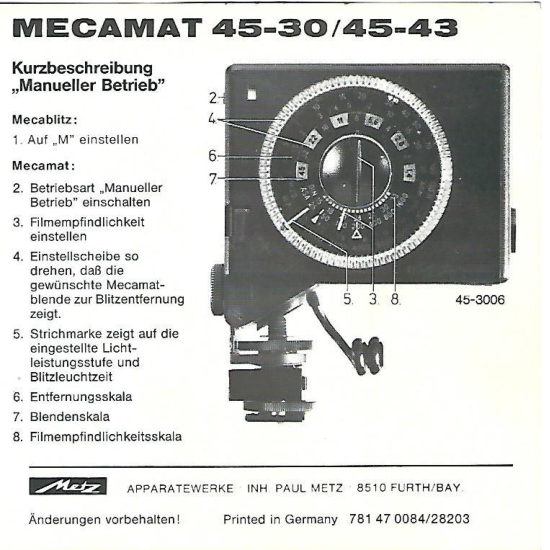
From the M. Butkus archive. Original publisher and archive notices are retained.
Check the model and edition against your equipment.
PDF verified 2026-10-10.