Light meters
Minolta Autometer Viewfinders User manual
User manual for Minolta Autometer Viewfinders. 1 pages in English. Read the original PDF, download or print a copy without registration.
1 pagesEnglish1.2 MB PDF
Loading your manual…Open PDF directly
Document details
- Brand
- Minolta
- Model / document
- Minolta Autometer Viewfinders
- Document type
- User manual
- Language
- English
- Pages
- 1
- File size
- 1.2 MB
- Category
- Light meters
- Document date
- Not specified in catalog
Search available document text
Find a term, then jump to its page in the original PDF. Image-only pages may not be searchable; check the PDF for exact wording and diagrams.
Page 1 · Read text
VIEWFINDER 5/10°1I

MINOLTA

Ea-7rtr9—-5/10
Ea- F771 F—SWEREB OSE, Ca-F71 FW ERHEM AVEO LHRH TH, BHO BRIT ISAT TC, ARy YE AIR MIED TT REE

Et

LEROLID <M OLA Ea“ 7rte9—10.

Orrtv¥— QRKB Orvy— Oi O7r1-7—SRG OA ABOU a7 7479-7 7479 |

BYU RDER RBEPROT 1 EMSS. aT

07719 BB AOBH OA BT RIM (OME IE
1, Ca-7 7429-048 (BLED) Ex—-I- AMORA SHE TLOD Si) (BLES, ee
AILSA ICL TRIELET. (A) es 7 719s timmeoOME EMT Lal, | OI

O75 yyax—F—W Cd, MHP ISI LETRET, (B) LRMERRERTOdRICahET HEL. (AD | C3 .
OF hx I-IV E TI, BAL SLU RAS OLR ISLES TERT, ORRAMME BLE.) i nena

2, RHBEOMDREET, 27179 AMEBISSICLET. (C) mR AS-AIBLTMELET. =

<BRYALHD MR ORABYIDET ROBT

Fran

RLY ARM T ICEIT CNET. (0) sopacpcur arr
er —
weuray
aa aaa
emndeieimahl (OFS.5—F 16.) | (-REDEMRMRIS"REF ITS)

SRAM PARCROMMOI THE, RERFOMBOMAL ATO TERE,

VIEWFINDER 5°/10°IL

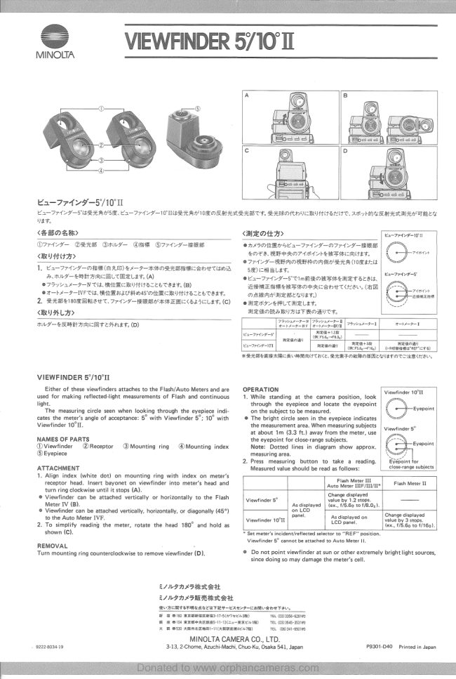
Either of these viewfinders attaches to the Flash/Auto Meters and are © OPERATION
used for making reflected-light measurements of Flash and continuous —_1. While standing at the camera position, look

Viewfinder 10°11

light. through the eyepiece and locate the eyepoint | /~ ;
The measuring circle seen when looking through the eyepiece indi- ‘on the subject to be measured. \ Eyepoint

cates the meter’s angle of acceptance: 5° with Viewfinder 5°; 10° with © The bright circle seen in the eyepiece indicates | “>

Viewfinder 10°. ‘the measurement area. When measuring subjects

Viewfinder 5°

at about 1m (3.3 ft.) away from the meter, use
NAMES OF PARTS ‘the eyepoint for close-range subjects.
@Viewfinder @Receptor @Mounting ring @Mounting index Note: Dotted lines in diagram show approx.
®Eyepiece ‘measuring area.

2. Press measuring button to take a reading.
ATTACHMENT ‘Measured value should be read as follows:
1. Align index (white dot) on mounting ring with index on meter’s

close-range subjects

receptor head. Insert bayonet on viewfinder into meter’s head and ate an me Ante| Flash Meter IL
turn ring clockwise until it stops (A). sano dialeyed
© Viewfinder can be attached vertically or horizontally to the Flash | Viewtinder 5° ere ro tops.
Meter TV (B). As displayed | (ex, 178.80 t0 178.0).
© Viewtinder can be attached vertically, horizontally, or diagonally (45°) 5
to the Auto Meter IVF. der tort | 2 Asdisplayed on _| Change displayed
x . Viewfinder 10°1L LOD panel by 3 stops.
2. To simplify reading the meter, rotate the head 180° and hold as lex, £78.60 t0 f/160).
shown (C). Set meter’s incident/reflected selector to “REF” position,
Viewfinder 5° cannot be attached to Auto Meter I
REMOVAL : .
Turn mounting ring counterclockwise to remove viewfinder (D). © Do not point viewfinder at sun or other extremely bright light sources,
since doing so may damage the meter’s cell.
RINGAAPRABA
SSWIALF RIAA BAL
SUIEMT STM AEE TRY eae some bE TEL
2 0io exeaawasso7eCm Tek OSE
MW SOC RRBORMAAS Cc. RREMIM) TEL OSI
% MSO AMMEMRINCRRIE TR) — TEL (031-6019
MINOLTA CAMERA CO., LTD.
9222803419 3-13, 2-Chome, Azuchi-Machi, Chuo-Ku, Osaka 541, Japan 9901-040 Printed in Japan
View original page 1
From the M. Butkus archive. Original publisher and archive notices are retained.
Check the model and edition against your equipment.
PDF verified 2026-10-10.