Light meters
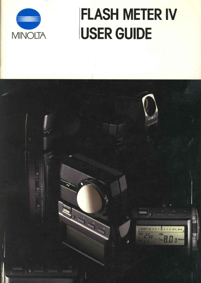
Minolta Flash Meter IV User manual
User manual for Minolta Flash Meter IV. 44 pages in English. Read the original PDF, download or print a copy without registration.
44 pagesEnglish4.5 MB PDF
Loading your manual…Open PDF directly
Document details
- Brand
- Minolta
- Model / document
- Minolta Flash Meter IV
- Document type
- User manual
- Language
- English
- Pages
- 44
- File size
- 4.5 MB
- Category
- Light meters
- Document date
- Not specified in catalog
Search available document text
Find a term, then jump to its page in the original PDF. Image-only pages may not be searchable; check the PDF for exact wording and diagrams.
Page 3 · Read text
The Minolta Flash Meter lV  is an extremely versatile exposure meter designed to
measureboth continuous (ambient) and f lash light sources.
1. Separatemeteringand adjustmentfor ambientand flashexposures.
   o A guide-valuefunction indicateshow the flash's power level should be adjustedto
     obtain correct exposure.
   o  Aperture-priority measurementsfor flash are possible and the guide value will
      indicate how to obtain correct exposure.
   o  Exposuresettingscan be adjustedafter taking a measurement.
   o By using the analyzefunction, the effect of combiningflash with ambient light can
     be calculatedin advance.
2. Multiple-datamemory and both digitaland analogdisplays.
   o A built-in microcomputer storesup tc two measurements.
     .   All exposureinformation is displayedon the illuminatedLCD panel.
   o When used with the memory function, the analog display can be used to quickly
     compare up to 3 readings.

3. Cumulativeexposure readingsare possiblewith ambient or flash light
  usingeither reflected-or incident-lightreadings.

4. Wirelessdata transferto Minolta/MAXXUM9000 and Minolta/MAXXUM
  7000 camerasvia the Data ReceiverDR-1000.

5. A  full rangeof accessoriesare availableto increasethe versatilityof the
  FlashMeter lV.


                   www.orphancameras.com
View original page 3Page 7 · Read text
PREPARATIONAND BASIC INFONIMATtrCIN

P O W E R                                                  Autonratic battery check
  The Flash Meter lV is powered by a singleAA-size        Even with power supplied continuously to the
battery that  fits  into  battery chamber A. A  1.5v       meter's memory, the meter's power consumption is
alkaline-manganeseor  carbon-zinc or  1.2v nickel-      minimal. To further conservepower, the Flash Meter
cadmium battery can be used.                               lV  employs an automatic cancelling feature that
  The  F lash Meter  lV's   inf rared transmitter  is       clears the  display approximately 4 minutes after
powered by a separate battery that  fits into battery       taking a readingor pressinga key. When the display is
chamber B. When using the optional lR Receiver-       off ,  the  meter can be activated by  pressing the
Trigger or Data Receiver DR-1000, a 6v alkaline-      on/recallbutton. The last displaywill then appearon
manganese(4LR44, Eveready537 or equiv.) or 6.2v       the LCD panel.
silver-oxide(4SR44, Eveready 544 or equiv.) battery        As battery power decreases,the LCD display will
should be installedin battery chamber B.                    blink when taking a measurement.lf  this occurs,
                                                                   install a new battery.
 I nstalling battery (ies)                             When the battery  is completely exhausted, the
1. Remove battery cover by slidingit in the direction     LCD display will remain blank even after pressing.the
       i nd i cated.                                               on/recall button.


                                                                                                                                                                                                                                                                                                                                              . 4 . " 3 s . . 2.   - 1  . 0 .          I    .  2 8 .  3 r {
                                                                                                                           FHE,f    ft          Fflo
                                                                                                  DU      f.Df       I'  frcoRo                                                           %--\


 2. Insert battery(ies) into  appropriate chamber(s)
   with plus (+) and minus (-) ends as shown in the
    battery chamber. (The meter will  not operate
   unlessthe battery is installedcorrectly.)


3 . Realign battery cover and slide  it towards the
   meter until it snapsinto place.


                           www.orphancameras.com
View original page 7Page 9 · Read text
ATTACHING MEASUREMENTHEADS

1. Incident-lightmeasurement                               2. Reflected-lightmeasurement
   For taking incident-lightreadings,hold the meter          Reflected-lightreadingsshould be taken from the
at the subject position with  the spherical diffuser      camera position while looking at the subject through
pointed  directly  towards the  camera. Since the       the eyepiece.
diffuser should receivethe same illumlnation as the
subject, the meter's receptor head rotates up to 270"
to make it easierto take readings.
  A  spherical diffuser is supplied with the Flash
Meter  lV  and should be attached when making
incident-lightreadings.To take readingsof extremely
bright flash or continuous light sources,the optional
4X  or 8X spherical ND diffuser can be used. For
determininglighting ratios,the optional flat diffuser
can be attached.
o  For macrophotographyand close-upphotography,
the optional Mini Receptor plugs into the socket on                                                   The receptor head can be rotated up to 270o tothe side of the Flash Meter lV's receptor head. This                                             make it easierto take readings.receptor can be used to measure ambient and/or
flash light  in  positions inaccessiblefor  the entire
meter body.

To attach diffuser:
   Align the dot on the diffuser with the bayonet
index and  insert the  diffuser's bayonet into the
receptor-headsocket. Rotate the diffuser clockwise
to secureit.


                                                  The reflected-light attachment supplied with the
                                                    meter has a 40" angle of view. The optional View-
                                                             finder 5o or Viewfinder IO.II can be attached for
                                                          taking spot readingsof selectedareas.
                                                              Reflected-light attachments are attached to the
                                                    meter in the sameway as the sphericaldiffusers.
                                                        o  For specializedmetering functions with the Flash
                                                  Meter lV, the Booster  ll can be used. lts highly
To remove diffuser:                                       sensitive receptor permits reflected-light measure-
   Rotate diffuser counterclockwise until  its dot       ments in  situations where precise metering is not
aligns with bayonet index and  lift diffuser out  of       usuallypossible.
receptor-headsocket.


                          www.orphancameras.com
View original page 9Page 11 · Read text
T A KI N G A M E A S U R E M E N T

   Aperture- and shutter-priority measurementsare        2. Aperture-priority measurement
both possiblewith the FlashMeter lV.                  When  the  meter  is used for  aperture-priority
i. Shutter-prtorttymeasurement                     measurements(at FNo. setting),the meter determines
  When the meter is used for shutter-priority meas-      the shutter speed (ambient-light measurements)or
urements(at TIME setting),the meter determinesthe      guide value (flash measurements)for correct expo-
aperture requiredfor correct exposure.                    sure.
                                                 Measuringa singleexposure
Measuringa singleexposure
                                                                                                                .  Measuringf lash light
o  Measuringf lash light
Setting before measurement:
Desiredshutter speed is set.

                                                        Setting before measurement: Result after measurement:
                                                   Desiredshutter speedand    Guide value is displayed.
                                                       aperture are set.

                                                        o  Measuringambient light


o  Measuringambient light
Setting before measurement:
Desiredshutter speedis set.                             Setting before measurement:Result after measurement:
                                                   Desiredaperture is set.      Required shutter speedis
                                                                             displayed

                                                        o  Measuringmultiple expo$ures


o  Measuringmultiple exposures                                                        Setting before measurement: Resultafter measurement:
 Setting before measurement:                                                    Desiredshutter speedand    Requirednumber of
 Desiredshutter speedis set.                             aperture are set.           exposuresare displayed.


                                       NOTE
                                                        o  By sliding decrease/increasecontrol, aperture or
                                                                     film speed can be changed even after taking a
                                                   measurement. The meter automatically displays
                                                             the new exposure settingswhen the user-setvalues
 N O T E                                                    are changed.
 o  By sliding decrease/increasecontrol, shutter speed      o When ambient light is too high for the aperture-
    or film speed can be changed even after taking a          shutter combination set, the  meter  will  auto-
   measurement. The meter automatically displays         matically change the  shutter speed to  obtain
   the new exposure settingswhen the user-setvalues         the correct exposuresettings.
   are changed.                                         o  Aperture and shutter speedcan be set in full-stops.
 o  After taking a measurement,the guide value (GV)        Guide value is displayedin full-stops.The number
   can be changed to select an aperture for correct          of  flashes (or exposures)is displayed in single-
   exposurewithout changingthe power level.                burst indications. lf the measuredvalue is between
                           www.orphancameras.comfull-stop indications,aperture value will be auto-
                                                           maticallyadjustedby 0.1 to 0.9 stop.
View original page 11Page 24 · Read text
I . M A K I N G A S I N G L E E X P O S U R EM E A S U R E M E N T     4. Pressthe measuringbutton to take a rneasurement.


B . M e a s u r i n ga m b i e n tl i g h t

Basicsettings
Analog-scale selector*     "CONTRAST" position
Display-modeselector           " F N o . " p o s i t i o n
Normal/analyze switch          " N O R M " p o s i t i o n

                                                        5. The meter will display the shutter speed required
    In aperture-priority mode, contrast scale is dis-           for correct exposure.
   playedevenwhen selectoris at "FNo." position.
                                                                                                                                                                                                                              - 4 . - 3 s . . 2 r { . 0
1 . Move single/multi-readingswitch to "SlNGLE"                                                       rue JJilU    @
   position.                                                                                                  ''o                                                                     5Y     1fifi^."'


2. Set measuring-modeselectorto "AMBl"


3. Slide function selectorto "FNo." position and set
   desired aperture by  moving  decrease/irrcrgdse
   control. Any aperture from  f lO.7 to f/90 can be
   set in full-stops.
View original page 24Page 28 · Read text
A P P L I E D M E A S U R E M E N T

M E M O R Y F U N C T I O N                                 Contrast scale
  Up  to two  flash andlor ambient-light measure'        The  contrast scale has a range from  -4   to +4
ments can be stored in the meter's memory. Measure-      stops. The "0"  position correspondsto the metered
ments can be recalledto the LCD display at a touch       value shown on the digital display. Readings are
of a button. Measurementsare simultaneouslyindi-      simultaneouslyindicated by pointers on the contrast
cated by pointers on the meter' analog scales.This       scale for determining contrast or for comparing two
makes it easy to compare two readingswhen deter-      measurements.For example,when mixing light from
mining exposure for two light sources,such as when       electronicflash with ambient light, the proportion of
m i x i n g f i l l - i n f l a s hw i t h a m b i e n tl i g h t .                          light from each source can be controlled. Once the
                                                  mixed  light  is measured, the  deviation between
                                                             flash and ambient light at a set shutter speed areAnalog scale
  When the f unction selectoris at "TlME" or "GV",      shown by pointers on the contrastscale.The contribu-
                                                                tion to total exposure made by each light sourcecaneither the contrast scale or the f-number scale can
                                                        thus be determined prior to making the exposure.be displayed by setting the analog-scaleselector to
the appropriateposition.
                                                                                                                                                                                  - 4 . - 3 s .  - 2    .   - 1   .  0    .   1    .   2 A .  3 . 4
F-numberscale                                                                                                                               a
   The pointer above the f-number scaleindicatesthe
aperture required for correct exposure.                =|l.,i,\'"'r=.LTJ^'"'

                   1 1.4 2 2.8 4 5.6 I  11 't6 2232 4564 90    .
   tr\o*"rr.LTJ^""'
View original page 28Page 32 · Read text
3. Shadow method                             How to clear the computed values
  By using this method, the shadow areasare given        To  clear the computed values, either press the
priority.                                                   on/recall button or the memory clear key. When the
1. Measure an area that you want to appear as the       on/recall button is pressed,the last measurementwill
  shadow on the film and enter the readinginto the      be displayed, and the mernorized values are stored in
  memory.                                              the meter's memory. When the memory clear key is
                                                     pressed,the last measurementwill be displayed, and
                                                         the memorized readingsare cancelled.


                                                                                            - 4 . , 3 s . - 2   .   I     .  0    .  1   .  2 t s . 3 . 4 .
                                             "rruEtt-t            -,   f,               -tr1   fl.ilt            To calculate an averagedexposure, two readings
                                                    must be memorized.
2. Pressthe shadow key.                               To calculate a highlight or shadow exposure, at
o When the shadow key is pressed,the letter "S"           least one reading must be memorized. lf there is
  and the shadowvaluewill be displayed.                 no memorized value when the highlightor shadow
o When the f-number scaleis displayed,one pointer         button  is pressed, the measured value will  be
   will indicatethe displayed(shadow)valueand the          automatically memorized and calculated.
   other pointer will indicatea memorizedvalue.                         lf two readingshave been memorized,the shadow
o When contrast scale is displayed,the "0"  position          calculation will be based on the lower of the two
   indicates the shadow exposure value, and the          readings;highlight calculation is based on of the
   pointer(s)indicatethe memorizedvalues.                  higher of the two readings.
o When an exposure is made based on the above        The calculatedexposure can be changedmanually
  measurement,the measured area will be exposed         by  moving the  decrease/increasecontrol while
                                                         pressingthe "S" or "H" key (seenext page).   as a shadow on the film.
                                                  The computed values for  highlight or shadow
                                                     exposurescannot be memorized.
                                                    Readingsmust be taken in shutter-priority mode
                                                                     (at "TlME"  setting). Aperture-priority readings
                                                       cannot be used for computing average,highlight,
                                                                 or shadow measurements.


                                                                    -rrur|  f1 . 4i-f2 2 . a8 5 . 6 FNo8 1 1_E1 6 2 _2 3 2 ( 5 6aMBl4 9 0 .
                                                       t-lt-it--rt-r        t-E  trtr  'i-                            *       1n                                f-l,;__l


                                                                                                                . 4 . . 3 s . " 2 . - 1 . 0 .     1   .  2 r .  3 . 4
                    @ r : n                                                    LI L'   *.tfi ^'"'
                                                                                                   r - "                                                                                     " a  n - l        ,,
View original page 32Page 33 · Read text
hIOW TO CHANGE COMPUTEDVALUES     2 . I N C I D E N T - L I G H TM E A S U R E M E N T

    i .  ffieflectee$-liqhtfi"leasurnrnents                       Even with incident-lightmetering, it is possibleto
                                                           adjust the displayed reading to bias the exposure
  !-"liEhlrghtpruority                                      according to  the  photographer's intentions. The
    The highlight exposure,which is calculatedby the       following are some situations where adjusting the
 meters gives an additional 2.3 stops exposure for the      exposurevalue may be useful:
 measuredarea.Manual adjustmentof this value is also      o When the photographer wants to adjust exposure
  possibleto meet individualneeds.                                to deliberately increaseor decreaseexposurefrom
    The produce an exposure value that places the          the normal metered value.
  highlight at the extreme end of the film's characteris-           .  When using a  filter that requires exposure com-
  tic curve, the measured value can be adjusted as         pensation.
  follows:                                                o When using a bellows or close-up ring for macro-
    While pressingthe "H"  key, move the decrease/        photography.
    increasecontrol upwards. Refer to the pointer on       o When using the Minolta Booster  ll  or Minolta
    the analogscaleto monitor the changein exposure         Booster.
    value. Refer to the digital readout on the LCD
    panel to check the setting.                            For increasedexposure:
                                                    To  deliberately increase exposure, move  the
       'Ir       rJecreasethe exposure value computed for the       decrease/increasecontrol while pressingthe "H"  key
  hiqhliq!"rt,use the followinq procedure:                        until the desiredchangeis indicated.
    While pressing the "H"  key, move the decrease/
    increase control  downward  and  monitor  the
    changeon the LCD panel.


        - 4  . 3 s  . 2        .  - 1      . 0         .      I      .   2 F  .  3  . 4

   TrMt    f      |.,                              aMbr
       L-I L'
 *7t__l
           Ll                             t                 \    EtlN.                N i.';i                                    - 4 . - 3 5 . , 2  .   - t   .  0    .  1   .  2 A .  3 . L
Take a measurement                   ilME  ,:   l.,                E       nucr
                                          L lL f                     ,l  _                           ut.,                 -#h,,,"
                                     ./                                For decreasedexposure:
                       Computed ExlN -2.5          To  deliberately increase exposure, move  the
                               (2.5 stops overexposure)      decrease/increasecontrol while pressingthe "S" key
                                     \                                         until the desiredchangeis indicated.
Press"H" key                                                ^""'ComputedExlN -23      @ , -L'_LIr ,
                                                                           ISO      i--   ,J(2.3stopsoverexposure)                         L  t  l    Er,N11.i,
                       Computed ExlN -2.O
  o{h*c{o,ruprir:n.it.y           (2.0 stops overexposure)
    The procedure for adjusted a shadow exposure is
  basically the same as described for highlight adjust-
  ment. For more exposure than the computed value,
 move the decrease/increasecontrol upward while
                  /'S"  pressing the      key. For less exposure than the
  computed value, move the decrease/increasecontrol
 downward while pressingthe "S" key.

 '*                            2 r .  3^'". L    [,fi
     I S O                 f  t                     T.,-l                            3 5 . - 2 . , 1 . 0 . 1 . 2 r . 3        L                          l  l     Ex,N
Take a measurement                        TIME, ,:  r-,        E          ^;;,                        E r t r           t n _
                                                      ,so .i4   l   .,,n I Ll.Li
                                     ./                     ComputedExlN +3.0
                             (3.0stopsunderexposure)
                                     \                  b . . 3 . .   2
Press"S" key                               '-ff-'               .      I      .   0      . u1     .   2 N .   3aMBl. 4Computed5a111+2.7                                .                il(2.7stopsunderexPosure)  -JTl   ,,,*www.orphancameras.com-1.\
View original page 33Page 35 · Read text
DISPLAY FOR ANALYZE FUNCTION

  When the  normal/an alyze switch  is moved to       Adjustrnent of settingswith analyzefunction
"analyze" position, ambient light and electronicf lash        The relative contributions to exposure by ambient
can be displayed separatelyby pointers on the analog      and flash light can be controlled by adjusting the
scale.The pointers above the analog scalewill indi-       shutter speed, aperture and/or flash power. Flash
cate the proportion of  light from each light source       contribution can also be controlled by changingthe
accordingto the aperture-shuttercombination in use.       flash-to-subjectdistance,power level, or aperture.

(example)
    ln  this example, the  readout shows that  the
difference between ambient light and flash is approxi-
mately 1 stop, that is, ambient light is half as great as
flash (at 1/60 sec. and f 12.8l'.


                                                 I       : l : l                                                      ' , i i
                        - 4 . - 3 s .- 2   .   - 1 ' . ' 0   .  1 o  2 4 .  3 . 4 ' ' '
     -fh5iME  f    ft         FNo.1.8,fi'o"o

Pointer a : Total exposure value is indicated by the
point at"0"  position.
Pointer b  : Blinking pointer indicatesproportion of
f lash light.
Pointer c : Indicatesproportion of ambient light.


                                                               After measurementof the above scene,the reading
                                             was as follows. The main subject is illuminated by
                                                      both tungsten lamps and electronic flash lights.


                                                                                                                                                                                                                                                                                                                                             . 4 . - 3 s . . 2 . - 1. 0 .     1   .  2 x . 3 . 4
                                                                                                                                                                                                                                                                                    rl!L. fir-r,-    r-,             *   f    f
                                                                                              *           J.iJ  fi ".".                                                                                                               [_ij-],


                           www.orphancameras.com
View original page 35Page 39 · Read text
',ffi
DETERMININGGUIDE NUMBERS       MEASURINGILLUMINANCE
FOR FLASH                                                 To measure illuminance of a continuous light source:
  The Flash Meter lV can be used to determine the        1. Set film speed to ISO 100, measuring mode to
guide number for the actual film speedin use.               "AMBl",  and  display indication to  "ExlN".
                                                           Attach the optional flat diffuser.
1. With the desired film speedset and the measuring-       2. Position the diffuser parallel to and as close as
  mode  selector set  for "CORD"   or "NON.C"          possible to the surface where light is to be meas-
   operation, move  the display-mode selector to          ured. Push the meter's measuringbutton.
   "ExlN", then attach the optional flat diffuser.            3. Read the "ExlN"  value and use it in the following
2. Position the meter at a specific distance (e.g', 3          formula:
   meters or 10 feet) from the flash unit and point
   the diffuser directly at the flash.
3. Press the measuring button  all the way  in  to                      lux = 2.5 x2"'*
   activate the meter's circuit. Then, trigger the flash
   manually. Read the displayed information in the
   formula below to determine the guide number:            Lux
                                                           100,000
                  r+                             10,000                              z                              1,000      G N = 1 . 1 4 x L x 2
       Where L = Flash-to-meterdistance                100
                                                                  1 0
                                                                   1
Example                                                                   o 2 4 6 8 1 0 1 2 1 4 1 6
  With a displayreadingof "ExlN 10.0" at ISO 100                                                                    lExlN.l
and a flash-to-meterdistanceof 1 meter, work the
                                                Examplefollowingequationasfollows:
                                                      With  a display reading of "ExlN  10.0" work
                                                         the equation as follows:
                                                    1 0
          G N = 1 . 1 4 x 1 x 2 '
                = 1 . 1 4 x 1 x 2 s                                        lux = 2.5 x2'*'*
                = 1 . 1 4x 1 x 3 2                                    = 2.5 x 21o'o
                = approx.36.5                                    = 2.5 x 1O24
                                                                = approx.2600
                                   NOTE
                                                  o  For precisemeasurementof illuminance,use of
                                                   the MinoltallluminanceMeteris recommended.


                            www.orphancameras.com
View original page 39Page 40 · Read text
I N F R AR E N R F M O T H C O N T F I C L

  The lR Receiver-Triggeris an optional accessoryto       Wire lessdata transfer:
the Flash Meter lV for use with any camera or lens.             .  Push the data transmissionbutton on the meter.
This unit receivesinfrared signalsfrom the meter to         The shutter speed and aperture settingsdisplayed
trigger a flash unit when taking flash exposure read-        on the meter will be transferredto the camera.
 i ngs.
  The optional Data ReceiverDR-1000 can be used
with Minolta (MAXXUM) 9000 and 7000 camerafor
wireless remote camera control. When mounted on
the  camera's accessory shoe, the  Data  Receiver
D R-1000  receives inf rared signals f rom the  Flash
Meter lV, thus enabling remote control of exposure
settings,flash firing, and shutter release.
  To use either lR Receiver-Triggeror Data Receiver
DR-1000,a 6v alkaline-manganeseor 6.2v silver-oxide     Hemote shutter release
battery must be installedin battery chamber B on the       o  For  simultaneous exposure-data transfer and
FlashMeter lV.                                                             shutter release,point the lR transmitter window at
                                                             the DR-1000 and pressthe shutter-releasebutton.
                                                  The exposure settingsdisplayed on the meter will
                                                     be automatically transferred to the camera, then
                                                             the shutter will be released.


The Data ReceiverDR-l000 attachesto the camera.
 Firirrgthe flash to take a meter readinE
 1. Set measuringmode to "NON.C".
 2. Press the measuring button once to activate the
   meter's circuit.
                                                The follclwingdata can be transferred:
                                                           Shutter speeds:  1l4OOOsec. to 30 sec. using               F/IJ                                    Minolta 9000
                                                           1/2OOOsec. to 30 sec. using
                                                                       Minolta 7000                 l       Aperture values: Any availableaperture from the
                                                                  rangeavailableon the AF lens in
                                                                            use.

                                              When the transferred data is outside the camera's
    Point the  lR transmitter window on the Flash      shutter-speedor aperture range, exposure is set to the
   Meter lV at the Data ReceiverDR-1000 and press      nearestavailable setting.
    the measuring button again to  trigger the flash
    u n i t .
 4. The flash will fire, and the measurementwill be
   taken and displayedon the meter's LCD panel.
View original page 40Page 41 · Read text
MEASURING.LEVELADJUSTER         OPTIONAL ACCESSORIES

                                                        Viewfinder 5"
                                                            This accessoryattachesto the receptor head an has
                          - 0    l s t o p   0    + O . l s t o p
               - 0    2 q f n n                                                             * 0 . 2 s t o p          an angle of acceptanceof 5". When attached, it  is
                                                        possibleto take precisereflected-lightmeasurements
                                                                 of both flash and ambient light.
               - f )    ? c t n n                                                                                     -f 0  ? qtnn

         - 0. 4 stop                           + 0 . 4 s t o p


               -  0  6 q f n n                                            * 0 . 5 s t o p


                                         + 0 . 6 s t o p         - 0 .6 stop  - 0 . 7 s t o p - 0 B s t o p + 1 0 . 7 s t o p
                                                       Viewfinder 10"  ll
                                             The Viewfinder10o ll can alsobe usedfor taking
.  Graduatedmarks indicate0.2 EV changes.            spot measurements.Precisereadingsare possibleby
  The measuring level of  the  Flash Meter  lV  is       positioningthe circlein its viewfinderon the areato
adjusted by Minolta to  its standard. Further adjust'      be measured.
ment of this setting (from +0.7 to -0.8 EV) is possible
when calibratingseveralmeters to a singlestandard.
  To adjust the measuringlevel, insert a screwdriver
into the slot on the measuring-leveladjuster'sscrew
and turn the screw to change its setting. Turning the
screw clockwise produces a higher reading; turning
counterclockwiseproducesa lower reading.

NOTE
                                                              Flat diffusero The measuringlevel should only be adjusted after
                                                   By attaching this diffuser, the Flash Meter lV candetermining that the standard setting will not pro-
                                                   be used to measure the lighting ratio between mainduce the desiredresults.
                                                 and auxilary light sources for either flash or contin-
STANDARD ACCESSORIES                     uous light sources. llluminance value for continuous                                                                    light sources and guide number of electronic flash
Spherical diffuser                                           units or M-classflash bulbs can also be determined.
   This diffuser is supplied with the Flash Meter lV
and is used to make incident-liQhtmeasurementsof
flash or continuous light.


                                                         Mini Receptor
                                                          This remote ceceptor plugs into the socket on the
Reflected-li ght attachment lT -21                          side of the Flash Meter lV's receptor head and is used
   For taking reflected-light measurementsof flash        to  measure incident and/or  continuous  light  in
and/or continuous light, this attachment can be used.      otherwise inaccessiblepositions.  lt  is particularly
 It has a 40o angle of acceptancethat corresponds to        useful for close-upand macro photography.
the field of view of most normal lenses.


                           www.orphancameras.com
View original page 41Page 42 · Read text
7I
                                                          Booster ll standard accessories:

   4X and 8X sphericalND diffusers                  35mm film plane attachment
      Both  of  these spherical diffusers incorporate a        Used on 35mm SLR cameras, this attachment
    neutral density element, and are used when light is       permits the most accurate measurementof the light
    too  bright for normal measurements.With the 4X       reachingthe film plane through the camera lens.
    diffuser, the meter's upward range is extended by two
   stops (2 EV); with the 8X, by three stops (3 EV).
   Operation of the meter remains the same as with the
   standardsphericaldiffuser.


                                                        Eyepiece attachment
                                               When attached to the eyepieceof an SLR camera,
                                                                      this attachment enables light measurement at and
                                                      around the center of the camera'sfocusingscreen.
    Sync. Cord  ll
       This specialcord connectsthe Flash Meter lV with
    the flash unit and the camera's sync terminal, thus
    making  possible  meter-flash and  carnera-flash
    synchron i zation w ithout changing con nections.


                                                         Spot-probe attachment
                                                     The brightness of  light on the ground-glassof a
                                                         view camera is measured with  this attachment. lt
                                                           permits accurate TTL  calculations of exposure or
                                                                        light contract on the subject and eliminate the need
    Booster ll                                                        for exposure calculationswhen the bellows is greatly
     When plugged into the accessory-receptorjack on      extended for close-upor macro photography.
    the head of the Flash Meter lV, this separatesensor
   enables making accurate rneasurementsof brightness
    at an SLR eyepiece,on an SLR focusing screen or
    view camera groundglass,through the eyepiece of a
    microscope,or at the film plane of a full-frame 35mm
   camera. The Booster ll may also be used for ordinary
    direct reflected-lightmeasurement,with an angle of
   acceptanceof upprox. 60o.


                                                        Microscope receptor
                                                                This receptor attaches to a microscope eyepiece
                                                                       for reflected light or flash measurementthrough the
                                                        microscopesoptics.
View original page 42Page 43 · Read text
:[:
SPECIFICATIONS
Type: Multiple-functionexposuremeter for measur-     Other:
ing continuousand flashlight;incident-and reflected-      Analyzefunction for meteringof mixed (contin-
light readingspossiblewith both digital and analog       uousand flash)light;
readoutson LCD panel;analyzefunctionfor readings/        Aperture-priority measurementfor  continuous
controlof continuousand flashlighting                        light or flash;
Receptor: Silicon photocell; receptor head rotates         Infrared remote control for any flash unit using
27O"                                                  optionallR
Receptionmethod:                                      Receiver-Trigger;wirelessdatatransfervia optional
   Incident: Sphericaldiffuser (or other optional       Data Receiver
   diffusers)                 ,                                                         \  DR-1000for use with Minolta (MAXXUM) 7000
   Reflected:40o-anglereflected-figfttattachment(or        and 9000 cameras
   optionalViewfinder5", Viewfinder10' ll)           Power source:One AA-size1.5v alkaline-manganese
   External receptors: Optional Mini  Receptor,     or carbon-zinc,1.2vnickel-cadmiumfor measurement
   MinoltaBoosterll                             and display; one 6v alkaline-manganese(4LR44,
Flashmeasuringrangesat ISO 100:                   Eveready537 or equiv.)or 6.2v silver-oxide(4SR44,
   fncident:f lO.7 to f/90 +0.9                       Eveready544 or equiv.) for infrared data transmis-
   Reflected:f 11.Oto f/90 +0.9 with 40o receptoror       sion
  Viewfinder10o ll; fll.4 +0.2 to f/90 +0.9 with     Dimensions:28x 68 x 153mm (1-118x2-11116x6
  ViewfinderSo                                             in.)
Continuouslight measuringrangesat ISO 100:           Weight:2OOg(7-1l16oz.lwithout batteries
     f ncident:EV -2 to EV 19.5
   Reflected:EV 1.0 to EV 22.5 with 40o receptor      Specificationssubjectto changewithout notice
   or Viewfinderloo  ll; EV 2.2 to EV 23.7 with
  Viewfinder5o
Measuringmodes:
  "AMBl": For continuouslightreadings
  "CORD": For electronicflash,M-classflashbulbs
   with or without  continuouslight; using flash
   unit'ssynccord or optionalSyncCord ll
  "NON.C": For electronicflash with or without
  continuouslight;triggercord not required
Cumulative readings: Possible with  incident or
 reflected-lightreadingsfor continuousor flashlight
Repeatability:10.1 EV
LCD digital readouts/displays:
  F-numbers:f lO.7 to f/90 +0.9 in 0.1-stopincre-
  ments
  ExposureIndex(ExlN) numbers:-15.9 to 45.6 in
  0.1-stopincrements
   Shutter speeds:30 min. to 1/8OOOsec. in l-stop                                 L
   increments
  Framesper secondfor movie cameras:8, 12, 16,
   18, 24, 32, M; shutter-sectoropeningof 180o
   Film-speeds:ISO 8  to ISO 6400 in 1/3-stop
  increments
  Numberof cumulativeexposures:0 to 9 (displays
   lastdigit of accumulatedreadingsover9 exposures
   in shutter-prioritymode)
  Guide value (GV) numbers:-8  to 8 in l-stop
  increments
LCD analogreadouts/displays:
  F-numberscale:f l1.O to f/90 (in 1/2-stopincre-
  ments)
   Contrast: -4.0  to 4.O in  1/4-stop increments
   (1l2-stopincrementsfrom -4 to -3 and 3 to 4)
   Other: Over- and under-rangesignal, memory
  marks(up to two), analyzefunctionindicator
                           www.orphancameras.com
View original page 43Page 44 · Read text
f
    CARE AND STORAGE
         Do not presson or damage the indication-display      When the meter  is to be stored, place  it  in  its
         window.                                                     original packing, and put   it  in an air-tight con-
                                                                        tainer with an appropriate amount of dehumidify-
         Do not subject the meter to shock or vibration.              ing agent,such as sillicagel.
         The meter should never be placed or  left  in the         Never attempt to disassemblythe unit. Any repairs
           glove compartment  or  other places in a motor         necessaryshould be undertakenonly by an author-
            vehicle, or eleswhere, where   it may be subject          ized Minolta servicefacility.
            to temperatures higher than 55oC, or lower than
          -2O"C,  as   it  may  be  permanently damaged.        The meter body may be wiped with a silicone-
           Particular care should be taken not to leave the          treated cloth to clean it. Do not allow alcohol or
          meter in sunlight or near sourcesof heat such as         chemicalsof any other kind to touch its surface.
           strong lights, etc. Do not store it in humid places,                                                                o    lf the meter is not to be used for two  or more            or near corrosivechemicals.                                                              weeks, it is advisableto remove the battery.
,l       .  The Flash Meter lV is designedfor use at tempera-                                                                 Other external parts of the meter amy be wiped           tures 50" and -10"C.   lf the unit becomes hottertl                                                                   with  a silicone-treatedcloth. Alcohol  or other
            or colder than this, operation will be more or less                                                               chemical solventsshould never be allowed to con-tlI         unsatisfactory.                                                                               tact  it. Never lubricate any part of the meter.
                    lf the meter is left or placed in direct sunlight for
          any long period, the indication-displaywindow
             will turn black.


                            MinolloComeroCo.,Lld.                  30, 2-Chome,Azuchi-Mochi,Higoshi-Ku,0soko541,Jopon
                            MinoltoComeroHondelsgesellschoflm.b.H.  Kurt-Fischer-Strosse50, D-2070Ahrensburg,WestGermony
                            MinoltoFronceS.A.                   357 bis,rued'Estienned'Orves,92100Colombes,Fronce
                             Minollo(UK)Limiled                    l-3TonnersDrive,BlokelondsNorth,MiltonKeynes,MKl4 sBU,Englond
                           MinoltoAuslrioGesellschoftm.b.H.        AmolienstroBe59-6.l,I l3l Wien,Austrio
                           MinolloComeroBeneluxBY.            Zonneboon39,3606CHMoorssenbroek,P.B.264,3600AGMoorssen,
                                                      TheNetherlonds
                          BelgiumBronch                    StenenBrugI l5 -  I 17,2200Antwerpen,Belgium
                            Minolto(Schweiz)AG                    RiedhofV Riedstrosse6, 8953 Dietikon-ZUrich,Switzerlond
                            MinoltoSlenskoAB                     Bronnkyrkogoton64, BoxI 7074,S-l0462 StockholmI Z Sweden
                            MinoltoCorporofion
                        HeodOffice                                     l0l WilliomsDrive,Romsey,NewJersey07446,U S.A.
                          LosAngelesBronch                3105LomitoBoulevord,Torronce,CA90505,U.S.A.
                          ChicogoBronch                    3000 TollviewDrive,RollingMeodows,lL 60008,U.S.A.
                                AllonloBronch                     5904 PeochtreeCornersEost,Norcross,GA30071,U S.A
                            MinoltoConodolnc.
                        HeodOtfice                       1344FewsterDrive,Mississougo,OntorioL4W lA4,Conodo
                          MontreolBronch                  376 rueMcMhul Sl Lourent,QuebecH4TlX8,Conodo                                                                       .l620
                          VoncouverBronch                     W.6th Avenue,Voncouver,B.CV6J I R3,Conodo
                             MinolloHongKongLimiled           Room208,2/F,EosternCentel1065KingsRood,HongKong
                            MinolfoSingopore(Ple) Lld.              l0,TebonGordensCrescent,Singopore2260
View original page 44Related documents and language editions
MinoltaPDF
Minolta PART ONE OF THE DEMONSTRATION
User manual
28 pages · EnglishRead →
MinoltaPDF
Minolta PART TWO OF THE DEMONSTRATION
User manual
27 pages · EnglishRead →
MinoltaPDF
yet another thisMinolta Flash Meter IV
User manual
50 pages · EnglishRead →
MinoltaPDF
Minolta Flash Meter IV Anleitung
User manual
44 pages · GermanRead →
From the M. Butkus archive. Original publisher and archive notices are retained.
Check the model and edition against your equipment.
PDF verified 2026-10-10.