Film cameras
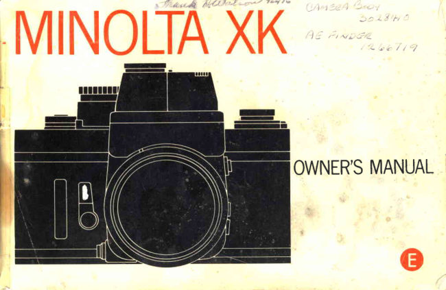
Minolta XK Motor User manual
User manual for Minolta XK Motor. 83 pages in English. Read the original PDF, download or print a copy without registration.
83 pagesEnglish3.3 MB PDF

Loading your manual…Open PDF directly
Document details
- Brand
- Minolta
- Model / document
- Minolta XK Motor
- Document type
- User manual
- Language
- English
- Pages
- 83
- File size
- 3.3 MB
- Category
- Film cameras
- Document date
- Not specified in catalog
Search available document text
Find a term, then jump to its page in the original PDF. Image-only pages may not be searchable; check the PDF for exact wording and diagrams.
Page 4 · Read text
Your Minolta XK Motor Drive is the world's first 35mm single-lens-reflex camera
expressly produced for motorized operation with automatic/manual exposure and
frame-rate control and interchangeable viewf inders. Based on the top-model XK camera,
this new premier-quality, heavy-duty unit can be set to take up to 3.5 frames per second
continuously as well as single frames with motor film advance. The quick-response AE-S
Finder meters over an extended range for auto-exposure control arrd keeps necessary
information visible while you view, including stepless LED/digital shutter-speed readout.
Human engineering with motorized automatic, safety, and fail-safe features never before
incorporated in such a camera enable a new high in easy handling and reliability. Besides
its own full line of range-broadening accessories, the XK Motor Drive uses all finders and
focusing screens for the XK, Minolta interchangeable SLR lenses, and applicable system
accessories for utmost compatible versatility.
   Before using your camera for the first time, study this manual carefully  all the way
through - or at least all the sections needed to cover your own photographic needs. As
you read, assemble the screen, finder, lens, body, battery pack, and holding strap as
described on pages 10 through 15; load batteries; and handle the camera and acquaint
yourself with its parts and features. Then load it with film and proceed to actual
picture-taking. In this way, you can obtain good results and begin to realize the
unusually great potential of your XK Motor Drive from the very beginning.
View original page 4
Page 6 · Read text
FOCUSING                             TECHNICAL INFORMATION     ....  69
  Byvariousmeans              ...47    CARE AND STORAGE             .....  74  Depth-of-fieldpreview         '...48                                                                                   76  lnfraredindex .                   ...'.48     TROUBLESHOOTING CHECKLIST ...  ..
MOTORIZED OPERATION      ......   49
  Frame-rateselector            ..49
  Single-frame operation                      . ... . 49
  Continuousoperation .....           .....  50
SHUTTER-PRIORITY FILM ADVANCE  .. 51
MANUAL OPERATION             ...  . 52
REWINDING FILM                        ...  53
UNLOADING FILM                        ,. 54
FLASH PHOTOGRAPHY           ...  55
MULTIPLE EXPOSURES            ...  58
INTE RCHANGEABLE FOCUSI NG
 SCREENS                            ..... 61
LENS-SCREEN COMBINATION CHART. . 62
  Compensation-factorselector ....  64
USING OTHER THAN MD
 oR MC LENSES                  ......   65
OPTIONAL MOTOR-DRIVE
 ACCESSORTES..             ...66
View original page 6
Page 7 · Read text
NAMES OF PARTS


               AE-S Finder
ShL tter-speed/f u nction selector
  Exposu re-adju stment control
        Long-exposu re selector
                Aperture scale
          Remote-control jack
             Operating button
              Button-lock ring
             Meter-coupler pin
 Motor battery-check indicator
           Stop-down button
   Motor battery-check button
   Linkage-gear cover
     (for 250-Frame Film Backl
        Standard Battery Pack

                 Holding grip

                www.butkus.us
View original page 7Page 8 · Read text
Scale-i   I lumination wi ndow
Grip "senswitch"
Display-range selector lever
Back-cover release knob
Manual-rewind crank
Exposure-control battery checker
Lens-release button
Neck-strap eyelet
Focusing grip
Sync. terminal
Sync. selector switch
Motor-drive housing
Exposu re-control battery chambe  r
Neck-strap eyelet
View original page 8
Page 9 · Read text
Exposure counter
                 Serial number
   Mechanical shutter release
   Manual film-advance lever
         AUTO-Iock release
   Film-speed selector release
Co mpensation-factor window
 Compensation-f actor control
          Film-speed selector
          Depth-of-field scale
               Distance scale
   Mount-lock release button
           AccessorY mount
                Flash contact


                 www.butkus.us
View original page 9Page 10 · Read text
Finder/screen release
Finder power switch
Finder eyepiece
Auto-rewind lever
Eyepiece-shutter lever
Shutter curtain
Frame-rate selector
Reset button
Sprocket
Tripod socket
Mu ltiple-exposu re control
Take-up spool
Holding-strap lug
Motor power-input socket
Back cover
Pressure plate
View original page 10
Page 11 · Read text
MAIN FEATURES


 Integral motor-drive body                             Shutter-priority auto frame-rate control
  The exclusive one-piece motor-drive body      The camera automatically adjusts the frame
enables reliability, efficiency, and ease of use     rate set as required for proper operation accord-
superior to detachable motor units, plus utmost     ing to the auto or manual shutter speed. Film
durability in extended heavy-duty use. lt incor-     will not advance unless proper exposure has
pofates motorized, automatic, and fail-safe fea-    been completed. Thus  if the speed required in
tures for unparalleled motor operation includ-   auto operation becomes too long to allow
 ing:                                               operation at the frame rate selected, the XK
 o A tension sensor to halt  f ilm advance at the    Motor Drive automatically reduces the frame
                                                                                               higher   end of a cartridge - no need to set frame     rate to provide proper exposure. lf a
   counter and no torn  f ilm                     speed then becomes possible, the frame rate is
o Fingertip motorized rewind with auto    automatically increased up to a maximum of
   switch-off and auto resetting to advance     the rate set, and so on.
   mode when back is opened
o Automatic film-advance stop if exposure-     Auto-control  info-center   f inder
   control voltage falls too low or batteries are   o The XK Motor Drive's new AE-S finder
   not properly loaded                                  features center-weighted metering by silicon                                                    '"photo                                                                          cell whose instant response and extra
Continuous automatic/manual exposure control         sensltivity maintain creative operation at
   In automatic operation, stepless shutter       low light levels.
speed is continuously adjusted electronically to   o lts integrated circuits automatically set step-
provide proper exposure at whatever frame rate         less shutter speeds for eight to 1/2000 sec.
the camera is set   "S" (single frame), 1, 2,3,       to provide proper exposure at the aperture                  -or "H" (3.5) frames per second without mirror        set for the light being metered and other
lockup. In manual mode, correct speed for        conditions.
proper exposure is indicated.www.butkus.us
View original page 11Page 12 · Read text
o Speeds being set in auto mode or correct   o Electronically controlled manual shutter
   shutter speed for proper exposure on manu-        speeds from 1 I2OOO to a full sixteen seconds
   al are continuously indicated in the finder       . "X" (1/100 sec. with X/FP sync.) and "8"
  by stepless LED/digital readout, along with         settings operable without battery power
   other necessary information: Lens aperture   o Convenient stop-down button and battery
    set, auto mode indication or shutter speed       check
   set on manual mode, and over-/under-range   o Easy-to-operate multipli-exposure control
    indication.                        o Eyepiece shutter for unmanned.or  similar
o A locking control allows setting the system     operation   to contanuously provide up to two stops                      Suj/eS,l5
  more or less exposure than would be set     Full motor-drive accessories for wide usefulness
   automatically.                      o Seperate battery pack and battery grip
                                o 250-Frame Film Back and loader
Proved XK-model features                o Connecting cords for actuating the built-in
   Designed and built to the even more rigid       electromagnetic relay switch using Minoltastandards required for motor operation, the XK                                                         intervalometers or wireless control units.
Motor Drive incorporates many of the same   o Long and short remote-control cordsadvanced featurirs from Minolta's proven top-
model XK camera, including:
o Familiar Minolta SLR bayonet lens mount     Full system lenses and accessories                                                   Besides its own, the XK Motor Drive of   and oversize mirror
o Interchangeable focusing screens and finders    course uses all Minolta and adapted Leitz lenses
o Electronically controlled focal-plane shutter    and applicable Minolta SLR system accessories                                                        for maximum compatible  versatility.   with titanium curtains that travel horizon-
    tally and permit electronic-flash sync. up to
   1/100 sec.
View original page 12Page 13 · Read text
ASSEMB LI NG COTVIPOI\I ENTS


General                                    thumb and foref inger and hold it so that the
1. Follow instructions exactly.                      bracket is on the upper side of the frame
2. Handle components with care.                 and toward the back of the camera over the
3. Never force parts.                                 corresponding curved recess in the camera's
4. ,Do not touch lens or screen surfaces with        screen receptacle.
   the fingers and be careful not to scratch or    3. Keeping the finder release button pushed all
   damage them.                               the way in, hold the screen at an angle,
                                                            insert the side toward the front or the end
Focusing screens                                toward the shutter release first, and let the
To install                                         screen drop into place. Then release the
1. Remove the top cap  f rom the camera body.        button.
2. Grasp the small projecting bracket on one
   side of the focusing-screen frame with    To remove
                                             Holding the finder/screen release button
                                          pushed in as tar as it will go, use the small
                                              bracket protruding toward back of camera to
                                                                      lift the screen out back side or rewind-crank
                                                          side  f irst.

                                   NOTE
                                          Care should be taken not to scratch the
                                                 surfaces or damage the microprisms or split-
                                                               field prisms of focusing screens.
              www.butkus.us
View original page 13Page 14 · Read text
Finders
To install                                            finder without the coupler properly posi-
1. Before attempting to install the AE-S Finder       tioned will damage the finder. The above  is
  or other coupling-type finder, make sure       not applicable to the Plain, High-Magnifica-
   that the meter coupler is positioned at the        tion, and Waist-Level Finders, which have
   red-dotted end of its slot. This is done by       no meter coupler.
   using your finger to move the coupler a-
   gainst the spring tension until it catches at    2. Remove finder cap and carefully align the
  the end of its stroke opposite the rest        finder properly (eyepiece toward back) with
   position (which has no red dot). A built-in        the camera's finder receptacle and push the
   automatic stop in these  f inders prevents       finder into it straight and evenly until  it
  them from seating properly unless this is        seats and locks firmly in place with a muf-
   done; forcibly attempting to seat a coupled         fled click.
View original page 14
Page 15 · Read text
3. Turn the shutter-speed selector dial clock-    To remove
   wise or counterclockwise  until it engages       Grasp the finder and, while pushing the                                                                                                  the   with the coupling pin on the body shutter-    finder release button all the way in, lift
   speed knob and starts turning with click-     finder straight out of its receptacle.
   stops. (Should the dial continue to turn
   freely without engaging, remove the finder,   NOTE
  by pushing the finder release button and          1f the shutter release is pushed while there is
     lifting the  f inder straight out of the recepta-    no finder installed on the camera when it is on
    cle, and turn the knob on the body a few    automatic mode, the mirror will stay up, and
    click stops in either direction. Then reinstall    the shutter will remain open temporarily. Push-
                                                       ing the reset button near the frame-rate selector   the finder -  not forgetting to reset the   coupler first, if applicable - and engage the    close the shutter at once. Even if this is not    dial with the pin.)                        done, the electronic circuitry will reset the
                                                  mirror and shutter automatically after about 30
                                                          sec. Toward not spoiling adjacent frames under
                                                   certain conditions, however, it is advisable to
                                                           reset the camera as quickly as possible.


              www.butkus.us
View original page 15Page 16 · Read text
13


Lenses
To attach
1. Remove the body cap from the camera lens
  mount and the rear cap  f rom the lens
   bayonet, both by turning the cap counter-
    clockwise.
2. Align the red mountin! index on the lens
   barrel with the red dot on the camera   To remove
   lens-mount flange; insert the lens bayonet       While pushing the lens-release button, turn
                                                                                                         go;    into the mount; and turn the lens clockwise    the lens counterclockwise as far as it will
    until  it locks into place with a click.            then lift the lens bayonet out of the mount.
View original page 16Page 17 · Read text
Standard Battery Pack
To attach                                To remove
1. With the screw running through the middle    1. Loosen the indented screw head on the
   of the battery pack aligned with the tripod       bottom of the pack with a coin or similar
   socket on the bottom of the motor-drive        object in the slot provided  if necessary, and
   housing, insert the battery pack's three-hole       turn the screw counterclockwise out of the
   6onnecting terminal into the thre*prong        camera's tripod socket.
   socket at the bottom of the body holding    2. Pull the battery pack's connecting terminal
    grip.                                                    straight out of the socket at the bottom of
2. Secure the pack in place by turning the        the body handgrip.
   indented screw head clockwise with the
  thumb and forefinger as far as it will go,   NOTE
   tightening it by a coin or similar object in   o For instructions on installing batteries in the
   the slot provided if desired.                        Standard Battery Pack, see p.21.
                                o Instructions for other motor-drive power
                                                    sources are packed with individual accesso-
                                                                          ries.


              www.butkus.us
View original page 17Page 18 · Read text
Holding Strap
To attach
   Push the large end of the keyholeshaped    To remove
slot of the strap's attaching bracket on over the      While pulling up on the free end of the
head of the camera body's holding strap lug and     retaining-spring tab of the' strap's attaching
slide it toward the small end of the slot until it    bracket as shown, slide it off the holding-strap
snaps securely in place.                                     lug.
View original page 18
Page 19 · Read text
SUMMARY OF OPERATION (on "AUTO")

             The steps pictured on this page outline    idea of how easy it is to operate for perfectly
               ordinary use of your XK Motor Drive on    exposed pictures and are keyed to correspond-
               automatic motorized mode. They give a basic     ing sections of the manual for ready reference.


                                          rq*{-                                                                       :,  "Rdj       i"q4U,-
          exposure and drive batter-      Open back cover and load film         Close cover         nce film to
     ies (pp.- 20,22l'.-E:r',::                    properly (p. 26).                  "1" lp.29l.


                                                                                                                -,


7  Grasp holding grip and unlock          Set lens aperture (p.  0).               Adjust focus (p. 47). '   operating button (pp. 33, 49).   8 www.butkus.us
View original page 19Page 20 · Read text
This brief guide may also be useful as a quick     substitute for the detailed instructions in the
refresher course after you have not used the      rest of this manual, which should be thoroughly
camera for some time. lt is not, however, a     studied and followed for best results.


4  Set film speed (p. 30).        5 andSet selectorturn finderdial powerto "AUTO"switch    $  Set frame rate (p. 49).
                                   on (pp. 40,341.


                                  l1Auto-rewind  film and remove      'l)Turn   f inder off a                                                                        '  ' cartridge (p. 53).                           '-  operating button
View original page 20Page 21 · Read text
BATTERIES AND POWER


                                                Exposu re-control batteries
                                       Two 1 .S-volt silver-oxide batteries, Eveready
                                    976, UCAR 5-76, or equivalent supply the
                                          power for controlling electronic shutter speeds
                                         and for meter and automatic exposure control
                                         when applicable.

IMPORTANT                           CAUTION
   Should viewing become impossible because     Do not use 1.3-volt mercury batteries,
the mirror of your XK Motor Drive remains up    which are available in a similar shape.
after the shutter is released (and film does not
advance), it does NOT mean that the camera
needs repair. The automatic electronic features
of the model cause this to happen if you release
the shutter 1) when exposure-control current is
off {i.e., if grip Senswitch  is not being held and
AE-S Finder power switch is off) on "AUTO"
mode, 2) when no finder is installed, or 3)
when battery voftage is insufficient at any
electronic shutter setting. To restore viewing
and usual function, simply turn the shutter-
speed/function selector to "X" or "8" (or push
the reset button) in case 1 or push the reset         .inbutton    case 2 or 3. For further details, see
p.41, 12, or 24, respectively. For any otherstoppage, see p. 76.    www.butkus.us
View original page 21Page 22 · Read text
2. After wiping terminals with a
                                     clean dry cloth and handling
                                       only by the edges, insert two of
To install                             the specified batteries plus (+)
1. Starting  it with a coin or similar       side out into the sleeve on the
   object if  necessary, turn the        inside of the cover. (lf batteries    3. Replace the cover and screw it   cover of the exposurecontrol      are inserted improperly, they        in clockwise as far as it will go,
   battery chamber counterclock-        will not make contact, and no       tightening it with a coin or
   wise and remove it.                     current will flow.)                         similar object if desired.
View original page 22Page 23 · Read text
20


                To test                               NOTE
                     Depress the battery checker lever toward        Batteries do not have sufficient power for
                the bottom of the camera. lf the red lamp     proper operation when the check lamp does not
                                                                          I ights, batteries are serviceable.                 come on even though finder display may light.
                   Test batteries immediately after installing
                  them. lf the lamp does not light, make sure that   CAUTION
                   they have been inserted correctly.               To avoid undue battery drain, do not keep
                          Batteries should be tested from time to time    the battery-checker lever depressed for more
                      thereafter, particularly before starting pictur+     than a second or two.
                   taking sessions or trips. A set of batteries will
                    usually last for about one year.


                          www.butkus.us
View original page 23Page 24 · Read text
Motor-drive batteries
To install
   The following installation instructions apply
to the standard battery pack only, which is
attached to the camera as indicated on p. 14.
For other motor-drive power sources, see in-
structions packed with individual accessories.
                                                                3. Align the white marks on cover
                                2. lnsert five penlight (AA) size 1.5     and chamber rim, and push
                                         volt sealed carbon-zinc batteries        straight in on the cover until it
1. Squeeze in on the grips on one      with plus (+) and minus (-)      snaps securely in place. (lf  it
  end of the standard battery       ends positioned as indicated in-      shaped so that it will not seat
   pack and remove the chamber         side the chamber; the center bat-       properly if the white marks are
    cover.                                     try should be plus-end down.           not aligned.)
View original page 24Related documents and language editions
From the M. Butkus archive. Original publisher and archive notices are retained.
Check the model and edition against your equipment.
PDF verified 2026-10-10.