Flashes & lighting
Miranda 530TZ flash User manual
User manual for Miranda 530TZ flash. 18 pages in English. Read the original PDF, download or print a copy without registration.
18 pagesEnglish1.2 MB PDF
Loading your manual…Open PDF directly
Document details
- Brand
- Miranda
- Model / document
- Miranda 530TZ flash
- Document type
- User manual
- Language
- English
- Pages
- 18
- File size
- 1.2 MB
- Category
- Flashes & lighting
- Document date
- Not specified in catalog
Search available document text
Find a term, then jump to its page in the original PDF. Image-only pages may not be searchable; check the PDF for exact wording and diagrams.
Page 1 · Read text
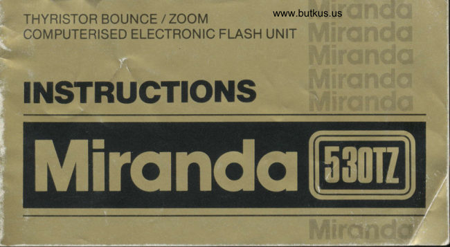
www.butkus.usTHYRISTOR BOUNCE  / ZOOM
COMPUTERISED ELECTRONIC FLASH UNIT

INSTRUCTIONS
View original page 1
Page 2 · Read text
PART IDENTIFICATION (Fig. 1l
           1) ZoomlBounce  f lash head
             2l  Battery cover
I          3) Sensor
             4l Auto/Manual selection switch
I          5) Mounting shoe
           6) Locking nut
10           7l Synchro cord socket
                         angle indication window11          8) Light           9) Bounce angle indicator
          10) Exposure calculator
 2               1 1) Auto check lamp
13         121 ON/OFF switch
          13) Ready lamp
          141 Test button
           15) Synchro cord
          16) Diffuser (wide angle diffuser)

  Fis.1
View original page 2Page 5 · Read text
ATTACHMENT TO CAMERA {Fig.3}
1) The flash unit has a "Hot Shoe" base and can
   be attached directly to a camera having a flash
   accessory "Hot Shoe" contact, which will
   hold the  f lash unit and provide the electrical
   connection between camera and flash when
   the locking nut is tightened.
2) A synchro cord is supplied for non-hot shoe
   type cameras to electrically connect the  f lash
    unit to the "X" contact socket of the camera.

ZOOM HEAD
The flashgun has a 3-position zoom head. For
35/40mm lenses set the head to the 'N' position;
for 50/55mm lenses use the 'S' position; for
telephoto lenses use the 'T' position. For wide-
angle lenses, set the head to the 'N' position; fit
the wide-angle diffuser and set the calculator to
the 'W'position.
View original page 5Page 7 · Read text
FLASH OPERATION -- READY TEST                                            (Fig.5)
                                       1) Turn the power switch on.
                                   2) Confirm whether ready lamp lights up.
                                   3) Push the TEST button, flash should go off.
                                   4) Wait for ready light before taking pictures.
                                     5) When finished taking picture, turn the power
                                             switch OF F.


www.butkus.us


                   Fis.5
View original page 7Page 9 · Read text
HOUI' TO USE THE WIDE ANGLE DIFFUSER
                           (Fis.7l           ml
              A 28mm lens can be used when the diffuser  is
                  mounted. Always set the angle indication
                 window at "N" when using the
                        diffuser.  lt is not possible to use a 28mm lens
                        at other settings.

                    Attaching to the flash unit  :
                  1) Push the knob of the diffuser gently into the
                          unit as indicated.
                 2) Push and insert as shown in the illustration.
                     Detach ing the diffuser:
                   Push the knob of the diffuser in the direction
                     of the arrow and pull out, as indicated in diagram.

Fig.7
View original page 9Page 11 · Read text
APERTURES AND DISTANCES FOR                 3) On the front of the flash body, set the auto/
                                                 manual switch to the red or blue mark.AUTOMATIC OPERATIoN  (Fig. 8)
The flash unit has two automatic operation            4)  Set the camera lens to the F-stop on the dial
settings designated by the colours red and                of the exposure calculator which coincides
blue. The shooting distance depends on the             with the Blue or Red Auto mark - whichever
zoom position of the flash head. The blue             you are using. The effective flash range can
setting is for shooting at distances of up to            be read-off the dial.
17 feet (5 meters) at f/4 (ASA 100/DlN21).         IMPORTANT: Distance figures for flash
For longer distances, use the red setting which           operation are approximate. Actual flash
allows shooting up to 21 feet (7 meters)                   distances depend on the reflective properties
at F2.8 (ASA 100/D lN21)                               of the surroundings. Light walls and ceilings
The shooting distance changes when lighting/               in small rooms enhance flash. Dark, non-
bounce angle is changed.                                       reflective surfaces and surfaces at a distance
1) Check the ASA number of your film and set         from the flash inhibit the flash effectiveness-
    this number in the ASA/DlN window.
2) Use the other slider to set the flash to W, N, S
   or T, according to the lens you are using. (W
   when using the wide-angle diffuser.)
View original page 11Page 13 · Read text
* NOTES ON AUTOMATIC OPERATION             can be used with the flash unit in automatic.
                                                               Therefore, please read the camera instruct-
    1) When shooting outdoors in bright daylight              ionsl.
        the auto check facility will not be reliable.
        Use the Manual ooeration mode therefore for
        daylight photography.
      2l   It is advisable to wait for a second or two
         after the ready lamp glows before taking a
        picture. This allows the flash to build-up to
?-         its maximum capacity.
       For cameras with automatic flash mecha-tl3)         nisms, set the flash unit to manual operation
        (depending upon the type, some cameras
        I


     l
View original page 13Page 17 · Read text
USING THE COLOUR FILTERS:
When you use the filters some light is blocked
off so that the camera lens must be opened
wider than indicated by the guide number scale.
lf the flash is used as an addition or auxilliary
light source (e.9. as a fill-in flash) the lens need
not be opened as far as when the flash gun is
the main source of light. Colour filters can
only be used on the manual setting.
View original page 17
Page 18 · Read text
www.butkus.us
SPECIFICATIONS
Guide Number: 32 (ASA 25iDlN 15 in feet) with   Flash Duration: 1/10O0 sec. on manual
                                                                                                 sec. on auto                   flash head in "N" position                        1/5000 - 1/10O0
             20 (ASA 10O/DlN 21 in meters)    Bounce Angle: 0o - 90"                with  f lash head in "N" position                                            Power Source: Four 1.5 size AA Alkaline batteriesAnsle or coverase:
                       ilJii.".ltt' :3.               SensorRecyclingMeasuringTime: 7Angle:10 sec.Approx.(approx.)20o                                                                        -                  {when flash head is in "N"                                          Number of Flashes:                                                         Approx 80 times with fresh                     position)                                                                          Alkaline batteries
Automatic Operating   Approx. 3-16 ft.       Dimensions: 190mm x 87mm x 56mm
Range (ASA 100/DlN 21):(1-5 m.l at't14          Weight: 286 gms.                       Approx. 3-21 ft.
                       (1-7 m.) atf 12.8


Because we continually strive to improve our products we may change specifications without prior notice.


16
View original page 18From the M. Butkus archive. Original publisher and archive notices are retained.
Check the model and edition against your equipment.
PDF verified 2026-10-10.