Flashes & lighting
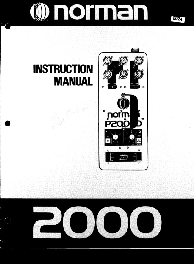
Norman 2000 flash User manual
User manual for Norman 2000 flash. 9 pages in English. Read the original PDF, download or print a copy without registration.
9 pagesEnglish2.2 MB PDF
Loading your manual…Open PDF directly
Document details
- Brand
- Norman
- Model / document
- Norman 2000 flash
- Document type
- User manual
- Language
- English
- Pages
- 9
- File size
- 2.2 MB
- Category
- Flashes & lighting
- Document date
- Not specified in catalog
Search available document text
Find a term, then jump to its page in the original PDF. Image-only pages may not be searchable; check the PDF for exact wording and diagrams.
Page 3 · Read text
Welcometo the Normanfamily of interchangeableflash equipment.
You havejust purchaseda Norman2000 flash unit that will provideyou with yearsof dependableservice.lt has a heavy
duty 2000 watt-secondcircuit,and severalexclusivedesignfeaturesand conveniencesnot foundon othercommercially
availableflash equipment.
          ($) O flash ratio feature that allows you to effectivelyhave two power units in one so you can
             obtainmore lightfrom some lightsthan others.

          A ratio light distributionfeaturethat allowsyou to adjustthe modelinglamp intensitiesin
              directproportionto the flash outputs.
         (0)  s"u"n lampheadoutlets!
          A heavyduty transformerlesscircuitthat enablesyou to flashthe unit for extendedperiods
             withoutoverheatingthe power supply.This transformerlessdesign has also reducedthe
            weightby 20 lbs. over our previoustransformertype units.
             Interchangeablewith the completeNormanSeries900 equipmentlinewhich includesover
            50 items-  reflectors,snoots,barn doors,powersupplies,umbrellas,diffusers,etc.
It is our sinceredesirethat you will benefitfrom the engineeringand manufacturingexpertisethat has broughtyou this
uniquesystem.
lf we can be of serviceor if you have any suggestionsor questions,pleasedo not hesitateto contactus.


           2000 W-S Outlet
                                                              Two LampheadOutlets
      Four LampheadOutlets                                                                for Output#2
                  for Output#1


                                                                              800/ 1200Switch
                                                                                                for Output#2


            400/800 Switch
                 for Output#1                                                 Dual Modeling
                                                             Lamp Dimmers
                                                                                      (calibratedin f/Stops)


                                                             TEST Button/ READY Light
                                                         (1OO%when lit)             ON Light


                                                       MDL (Model)Switch
      PWR (Power)Switch                                     SYNC Outlet
                                                    RESET15AmpCircuitBreaker
          115 Volt AC Inlet                                                  O


                        www.butkus.us
View original page 3Page 4 · Read text
Save fhese lnstructions
         IMPORTANTSAFEGUARDS
                           in accordancewithUL 122specificationsfor photographicequipment

  Whenusingyourphotographicequipment,basicsafetyprecautionsshouldalwaysbefollowed,includingthefollowing:
   1. Readandunderstandallinstructions.
   2. Caremustbetakenas burnscouldoccurfromtouchingthemodelinglamp.
   3. Donotoperatetheappliancewitha damagedcordor if theippliancehasbeeddroppedordamageduntilit hasbeenexaminedby
    a qualifiedserviceman.
   4. lf anextensioncordis necessary,a cordwitha suitablecurrentratingshouldbeused.Cordsratedforlessamperagethanthe
     appliancemayoverheat.Careshouldbetakento arrangethecordso thatit will notbetrippedoveror pulled.
   5. Whenpractical,unplugtheappliancef romtheelectricaloutletwhennotin use.Neveryankthecordto pullf romtheoutlet.Grasp
     theoluoandoullto disconnect.
   6. ToaVoidelectiicshockhazard,do notdisassemblethisappliance,buttakeit to a qualifiedservicemanwhenserviceor repair
    workis required.Incorrectreassemblycouldcauseanelectricshockhazardwhentheapplianceis subsequentlyused.

EXPTANATIONOFINDICATORSANDCONTROTS

                            AC INLET
Connectsto theAC powercable.TheAC inputvoltageis 115volt,60 Hz.

                        PWR Switch
ControlstheACpowerto theflashcircuit.Themaincapacitorsautomaticallydischargewhenthe PWRswitchis off.
NOTE-   it is not necessaryto turn the PWRswitchoff whenconnectingor disconnectinglightson powersupplies
manufacturedatterserial#1 34t10.

                             MDL Switch
Turnsthe modelinglampson or off.TheMDLswitchoperatesindependentof the PWBswitchso thatthemodelinglampscan
be lurnedon with the flashcircuitlett off.

                           ON Indicator
llluminateswhenthe PWRswitchis on and whenthe ooweris reachinothe circuit.

                            TEST/READY Light
llluminaleswhenthe circuitreaches100%voltagestabilizedoutput.The unitcan be flashedby depressingtheTEST/
READYlighl.

                          RESET Clrcult Breakel
Ratedat 15 amps.lt automaticallyprotectstheflashcircuitagainstexcessiveovsrloads.lf theON lightgoesoflbutthePWR
switchandmodelinglampsareon, the RESETbreakeris probablyactivatedcausingths buttonto popout about% inch.To
resetthe breakersimplywait about30 secondsand deprsssit back to its normalposition.

                              SYNC Outlet
Triggersthe flash.Plugyourcamerasyncextensioncordintothisoutlet.Properpolarityis importanlwithmostcameras
 (camsraswithgroundsdsynccontacts).Tocheckpolarity,simplytouchanyexposed(non-paintedandnon-anodizsd)metal
on the camerabodyto anyexposed(non-paintedand non-anodized)mstalon the flashunit,lf the unitflasheswhenthisis
done,reverssth6synccordto achisvethecorrectpolarity.Thissstablishesa commongroundbetweenth6camerabodyand
 the flashunit. lf the polarityis incorrect,the unit couldself flashor tlash intermittontly.
View original page 4Page 6 · Read text
EXPTANATIONOFINDICATORSANDCONTROLS

                                2000W-SOutlet

Enablesyou to obtainthe f ull 2000 w-s outputon a singlelamphead.The 400/800 switchand the 800/ 1200switchmust
be both set to their maximumoutputsto achievethe full 2000 w-s as illustratedbelow:


                     1200


The output#1 and output#2 channelsare automaticallytied togelher(in parallel)whenusingthe 2000w-s outlet'
Therefore,as you inseitadditionaltampheadsto any otheroutlet,the lightoutputis splitevenlyamongthe lightsas
 illustratedbelow:
                    p                                     'T                                                                 ll
                             p
                                                                       s00w-s                                                                                                                          /{

                                                                      1200


        CAUTION-  Only inserta connectorinto the 2000 w-s outletwhen the ready light is on or when
           the power supply has been off for at least ten seconds.Units manufacturedbeforeserial number
         13460 must have the PWR switch "off " for at least ten seconds before insertingor removing
         lampheadsfromany outlet.
View original page 6Page 8 · Read text
EXPTANATIONOFINDICATORSANDCONTROLS

                          MODELING LAMP DIMMERS
Dims the modelinglampsso that they will ratioto the flash outputs.The dimmersare calibratedin one f/stop increments
 (fourf/stop range).Properadjustmentof the modelinglampdimmersenableyou to see the actuallightratiosand shadow
detailwith the modelinglamps.You can also raiseor lowerthe overallmodelinglamp brillianceand stillmaintainthe
proper balance to the flash. A real asset when photographingpeople where the modelinglamps are uncomfortably
bright for the subject.Also convenientwhen all the flash outputs are on low power and you need more lightto focus
on the subject.
DIMMER#1 -  Controlsthe modelinglamps on the four
  output#1 connectors.
DIMMER#2-  Controlsthe modelinglampson the two
  output #2 connectorsand on the 2000 w-s connector.               FThere is at/z f/stop relationshipbetween800 w-s and       800w-s                 1200w-s                           ffi
 1200w-s. Therefore,if one lightis at 1200w-s (output#2)
and anotherlightis at 800 w-s (output#1), the output#2
 (1200w-s) dimmercould be set to full and the output#2
 (800 w-s) dimmercould be set betweenfull and "1" (72
 f/stop) less than the modelinglampson output#2 (just
 likethe flash).Referto illustration#1:                 between Full & "1"                       Full
For additional  information  on the relationship
 between watt-seconds and  f lstops, refer to chart                              lllustration #1
 below.
 lf a secondlightwere addedto output#1 the flashoutputs      lf the modelinglamps are uncomfortablybrightfor the
on that side would be reduced by one f/stop (to 400 w-s    subject you can lower them in direct ratio by adjusting
each). This would enable you to still compose your    both dimmersby the same amount.See illustration#3:
lightingwith the modelinglamps.Referto illustration#2:
                 p   F      400w-s                                    400
                            1200w-s                w-sp                   1200w-s           ffi      400Fw-s                                         400 w-s
        800                                        800                      1200

         '31"between    &'(2"                      Full          bgtwggn"2" &"3"                               " 1 "
                            lllustrationlllustration #2#2                                                             lllustration  #3

            RELATIONSHIPBETWEENWATT-SECONDSAND f/STOPS (US|NGTHE SAME REFLECTOR)
     Remember,when you doublethe watt-secondsyou gain one flstop (400 w-s to 800 w-s equals a one f/stop gain; 800 w-s
      to 1600w-s equalsanotherf/stop gain).
     To get an increaseof 7zf/stop multiplywatt-secondsby 1 .5, For example,400 w-s x 1 .5 equals600w-s. This is at/zt/stop
      increase.Here is a chart that illustratesthis principle:
         100w-s
              to          equals -  1 f/stop gain
         200w-s
              to         equals-1flstopgain
         400w-s
              to         equals-%f/stopgain
         600w-s
              to           equals- 7zf/stop gain             ":""",":::,'"",".uu")::;:::         472f/stops
         800w-s
              to           equals- 7zf/stop gain
        1200w-s
              to           equals- 7zf/stop gain
       1600w-s
             to         equals-%f/stopgain                              :':,,',""::,"-oo'l),;;       2OO0w-s
      Therefore,increasingthe power from 100 w-s to 2000 w-s yields an increaseol 4Vzf/stops.
View original page 8From the M. Butkus archive. Original publisher and archive notices are retained.
Check the model and edition against your equipment.
PDF verified 2026-10-10.