Flashes & lighting
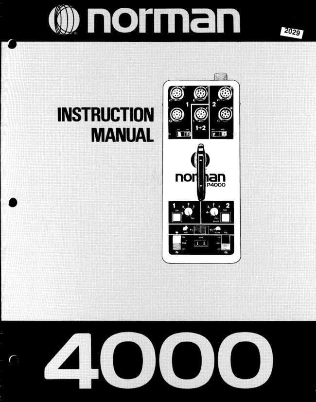
Norman 4000 flash User manual
User manual for Norman 4000 flash. 8 pages in English. Read the original PDF, download or print a copy without registration.
8 pagesEnglish3.4 MB PDF
Loading your manual…Open PDF directly
Document details
- Brand
- Norman
- Model / document
- Norman 4000 flash
- Document type
- User manual
- Language
- English
- Pages
- 8
- File size
- 3.4 MB
- Category
- Flashes & lighting
- Document date
- Not specified in catalog
Search available document text
Find a term, then jump to its page in the original PDF. Image-only pages may not be searchable; check the PDF for exact wording and diagrams.
Page 3 · Read text
Welcometo the Normanfamilyof interchangeableflash equipment.
You havejust purchaseda Norman4000 power supplythat will provideyou with yearsof dependableservice.lt has sev-
eral exclusivedesignfeaturesand severalconveniencesnot found in other commerciallyavailableflash equipment.
          A flash ratio featurethat allows you to etfectivelyhave three power units in one, so you can    (.0             obtain more light from some lampheadsthan others.
          A ratio light distributionfeaturethat permitsadjustingthe modelinglamp intensitiesin direct    ('0proportionto the flash outputs.
    (0 Sevenlampheadoutlets!
          Up to 4000 w-s on a singlelight when using the LH4000LAMPHEAD.    ('0
           As littleas 200 w-s per flash with a singlelamphead.    (-0
             Interchangeablewith the completeNormanSeries900 equipmentline which includesover   (O           60 items-  reflectors,grids,snoots,barn doors,power supplies,umbrellas,ditfusers,gels,
               etc.
It is our sinceredesirethat you will benefitfrom the engineeringand manufacturingexpertisethat has broughtyou this
uniquesystem.

lf we can be of serviceor if you have any questions,pleasedo not hesitateto contact us.

       2000 W-S Outlet
                                                                Two LampheadOutlets
  Three LampheadOutlets                                                                     for Output#2
              for Output#1

                                                                     1+2 (2000W-S) outlet

                                                                       800/1600Switch
                                                                                                  for Output#2       2OOl4OOSwitch
              for Output#1


                                                                         Dual Modeling
                                                             LampDimmers
                                                                                        (calibratedin f/Stops)

                                                             TEST Button/READYLight
                                                                              (1000/owhen lit)


          ON Light                                                        MDL (Model)Switch
    FAST/SLOWSwitch                                         SYNCOutlet
   PWR (Power)Switch                                         RESET15 Amp CircuitBreaker

        115VoltAC Inlet


                       www.butkus.us
View original page 3Page 4 · Read text
Save fhese lnstructions

         IMPORTANTSAFEGUARDS
                                irraccordancewithUt 122specificationsfor photographicequipment.

  Whenusingyourphotographicequipment,basicsafetyprecautionsshouldalwaysbefollowed,includingthefollowing;
   1. Readandunderstandallinstructions.
   2. Caremustbetakenas burnscouldoccurfromtouchinothemodelinolamp.
   3. Donotoperatetheappfiancewitha damagedcordor if theappliancehasbeedilroppedordamageduntilit hasbeenexaminedby
    a qualifiedserviceman
  4. lf anextensioncordisnecessary,acordwithasuitablecurrentratinoshouldbeused.Cordsratedforlessam                                                                                                                                  -    appliancemayoverheat.Caredhouldbetakento arranoethecord!otnatit willnotbetrippedover0r pull'eO.
   5. Whenpractical,un.plugtheappliancef romtheelectricaloutletwhennotinuse.Neveryanktheiordtopullf romtheoutlet.Grasp
     thepluqandpullto disconnect.
  6. ToaVoidelectiicshockhazard,donotdisassemblethisappliance,buttakeit to a qualifiedservicemanwhenserviceor repair
    workis required.lncorrectreassemblycouldcauseanelectricshockhazardwhentheapplianceis subsequentlyused.'

EXPTANATIONOFINDICATORSANDCONTROTS
                            AC INLET
Connects to the AC power cable. The AC input voltage is 115 volt, 60 Hz.

                         PWB Switch
Controls the AC power to the flash circuit. The main capacitors automaticallydischarge when the PWR switch is off.
NOTE -    it is not necessaryto turn the PWR switch oft when connectingor disconnectinglights on power supplies
manufacturedafter serial #13480.

                          MDL Switch
Turnsthemodelinglampsonoroff.The IVIDLswitchoperatesindependentofthe PWRswitchso thatthemodelinglampscan
be turnedon with the flashcircuitleft off.

                           ON Indicator
llluminateswhenthe PWR switchis on and whenthe poweris reachingthe circuit.

                            TEST/READY Light
llluminateswhenthe circuitreaches100o/ovoltagestabilizedoutput.The unitcan be flashedby depressingthe TEST/
READYlight.

                          RESET Circuit Breaker
Ratedat 15 amps.lt automaticallyprotectsthetlashcircuitagainstexcessiveoverloads.It theON lightgoesoff butthe PWR
switchandmodelinglampsareon,the RESETbreakeris probablyactivatedcausingthe buttonto popout about74inch.To
resetthe breakersimplywait about30 secondsand depressit backto its normalposition.

                             SYNC Outlet
Triggersthe flash.Plugyourcamerasyncextensioncordintothisoutlet.Properpolarityis importantwithmostcamdras
(cameraswithgroundedsynccontacts).Tocheckpolarity,simplytouchanyexpossd(non-paintedandnon-anodized)metal
on the camerabodyto any exposed(non-paintedandnon-anodized)metalon the tlashunit.ll the unitflasheswhenthisis
done,reversethesynccordto achievethecorrectpolarity.Thisestablishesa commongroundbetweenthecamerabodyand
the flashunit. lf the polarityis incorrect,the unit couldself tlashor tlash intermittently.

                            FAST/SLOW Switch
Thenormalpositionis the FASTsetting.However,in situationswherelimitedAC poweris available,or whenusingthe P4OOO
POWERSUPPLYin coniunctionwith a portablemotor-generatorpowersource,you maywishto usethe SLOWsettingto
preventan overloadconditionon theAC source.
View original page 4Page 6 · Read text
EXPTANATIONOFINDICATORSANDCONTROTS
                                                    l+2 Outlet
              Enablesyou to obtainthe combinedoutputsof #1 and #2(up to 2000w-s)on a singlelamphead.The2OA/400 Switchandthe
             800/1600Switchmustbothbe settotheirmaximumoulputsto achievethefull 2000w-s.Connectthelighttothe 1+2Outletas
              shown.A secondlight may be used in any of the remainingfive outlets,to achievethe outputsshown below.
                       1000Fw-s                      1200w-s
tI
f


                                                      1+2

             1+2 OUTPUT-  Typicalsettingswith two lights
          500Fw-s               500 w-s  600 w-s               600F,w-s 1000w-s               000Pw-s


                                       800                          800
                                   ffir1+2                        1+2

              ConnectingadditionalLampheadsto the top outletscausesthe light to split evenlyamongthe units.
                                             #3 Outlet
              Locatedon the end of the powersupply.This connectoralwaysprovidesa fuli2000w-s of output,regardlessof the settingsof
             the2OO/400Switchandthe 800/1600Switch.Thispermitsyouto useone lightat 2000w-s whilesimultaneouslyusingother
                  lightsat outputsup to an additional2000 w-s.


                                                                    *4000 w-s
ur
t       HHffi


                            *4000 w-s on a singleLampheadis achievedby using an LH4000dual cable Lamphead.
View original page 6Page 8 · Read text
EXPLANATIONOFINDICATORSANDCONTROLS
                    MODELINGLAMP DIMMERS
Dimsthe modelinglampsto ratiowith the flash outputs.The dimmersare calibratedin one f/stop increments(fourf/stop
range).Properadjustmentof the dimmersenablesyouto seetheactuallightratiosand shadowdetailwiththe modelinglamps.
Youcan also raiseor lowerthe overallmodelinglampbrillianceand stillmaintainthe properbalanceto the flash.A realasset
when photographingpeoplein situationswherethe modelinglampsare uncomfortablybrightfor the subject.Also convenient
when all the lampheadsare on low flash power and you need more lightto focus the camera and/or view the subject.
DIMMER#1 -  Controlsthe modelinglampson the three
  Output#1 connectors.DIMMER#2 -  Controlsthe modelinglamps on the two           400Fw-s                 800 w-s
  Output#2 connectorsand on the 1+2 connector.
Output#3 (end connector)has no dimmercontrol.
Thereis a onef /stop relationshipbetween400 w-s and 800               400                800
w-s. Therefore,if one lightis at 800 w-s (Output#2)and the
otheris at 400 w-s (Output#1),the Output#2 dimmer(800
w-s) couldbe setto f ullandthe Output#1 (400w-s) dimmer
could be set to "1" (1 f/stop less).This would causethe
modelinglamp in the 400 w-s lampheadto becomeone
f/stop weakerthan the one in the 800 w-s light,thereby
 providingan accuratevisualizationof the effectsthe flash
 will produce.Referto illustration#1.                                                       lllustration#1
FOR ADDITIONALINFORMATIONON THE RELATION-
SHIPBETWEENWATT-SECONDSAND F/STOPS,REFER         lf the modeling lamps are uncomfortablybright for the sub-
TO THE CHARTBELOW.                                          ject you can lower them in direct ratio by adjusting both
                                                     dimmers by the same amount. See illustration #3.
 lf a secondlight were addedto output#1 the flash outputs
on thatsidewouldbe reducedby onef /stop (200w-s each).
Thiswouldenableyouto stillcomposeyourlightingwiththe
 modelinglamps.Referto illustration#2.                                                                           200 w-s
                                                                                800 w-s   FF200 w-s                800Fw-s

                                                                              800
              400


                             lllustration#2                                                     lllustration #3

           RELATTONSHTPBETWEENWATT-SECONDSAND f/STOPS (USTNGTHE SAME REFLECTOR)
    Remember,when you doublethe watt-secondsyou gain one f/stop (400w-s to 800 w-s equalsa one f/stop gain;800w-s
      to 1600w-s equalsanotherf/stop gain).
    To get an increaseot1/zt/stopmultiplywatt-secondsby 1 .5. For example,400 w-s x 1 .5 equals600w-s. This is ar/zt/stop
     increase.Here is a chartthat illustratesthis principle:
        100w-s
              to         equals-1flstopgain
        200w-s                                                total gain equals -  2 f/stops
              to          equals- 1 f/stop gain                                                               II        400w-s   Il              t0          equals-  tzzf/stop gain
        600w-s                                           totaLlgain equals-  1 f/stop
              to          equals -   l'z f/stop gain                                                          Stlnf/stop$        800w-s     t,
             t0          equals-  1rzf/stop gain
       1200w-s                                             totatgain equals-  1 f/slop
              to          equats*  tz f/stop gain
       1600w's
              to           equals- 7af/stop gain             totat gain equats-   t/qt/'stop        2000yv-   l
              to           equals- 1 f/stop gain
        4000w-s                 l
     Therefore,increasingthe power from 100 w-s to 4000 w-s yields an increaseof 51/ef/stops.
View original page 8From the M. Butkus archive. Original publisher and archive notices are retained.
Check the model and edition against your equipment.
PDF verified 2026-10-10.