Flashes & lighting
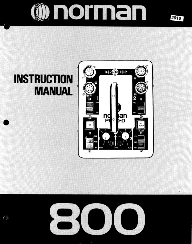
Norman 800 flash User manual
User manual for Norman 800 flash. 7 pages in English. Read the original PDF, download or print a copy without registration.
7 pagesEnglish2.9 MB PDF
Loading your manual…Open PDF directly
Document details
- Brand
- Norman
- Model / document
- Norman 800 flash
- Document type
- User manual
- Language
- English
- Pages
- 7
- File size
- 2.9 MB
- Category
- Flashes & lighting
- Document date
- Not specified in catalog
Search available document text
Find a term, then jump to its page in the original PDF. Image-only pages may not be searchable; check the PDF for exact wording and diagrams.
Page 3 · Read text
Welcometo the Normanlamilyot inErchangeableflashequipment!
  Youhaveiust purchasedthe Norman800flashunitlhat will provide)rouwithyearsof dependablss€rvics.lt has a hsavy-
  duty800watt-secondcircuit andsevsralexclusivetealuresandconveniencesnot foundon othsrcommsrciallyavailable
  flashequipment.

               n ratiofeaturethatallowsyouto adjustthemodelinglampintensitiesindirectproportionto the      @
                    flash outputs.

              A flash ratio feature that allows you to effectivelyhave two power units in one so you can
                  obtain more light from some lights than others.

           (D  O heavydutytransformerlesscircuitthatenablesyouto flashthe unitfor extendedperiods
                withoutoverheatingthe powersupply.Thistransformerlessdesignhasalsoreducedthe
               weightby 10 lbs.overour previoustransformertypeunits.

                 Interchangeablewith the completeNormanSeries900 equipmentlinewhich includesover 50       @
                tems -  reflectors,snoots,barn doors, power supplies,umbrellas,ditfusers,etc.

    It is our sinceredesirethat you will benefitfrom the engineeringand manufacturingexpertisethat has broughtyou this
  uniquesystem.

     lf we can be of serviceor if you have any suggestionsor questions,please do not hesitateto contact us.


         1<+211+2Switch
      (combinesor separates                                                 Dual LampheadOutlets
       Channel#1 and #21                                                                for Channel#2

     Dual LampheadOutlets
               for Channel#1                                          4OOl2OOSwitch for
                                                                     Channel#2


        4OOl2OOSwitch for                                     TESTButton/ READYLight
             Channel#1                                        (100%whenlit)

            ON Light


     PWR (Power)Switch
                                                        MDL (ModelingLamp) Switch

                                                         RESET 15 amp CircuitBreaker
Dual ModelingLamp Dimmers
        (calibratedin f/stops)

          115 Volt AC Inlet


                         www.butkus.us
View original page 3Page 4 · Read text
Save fhese lnstructions
@                                 in accordanceIMPORTANTwithIJL122specificationsSAFEGUARDSfor photographicequipment

         Whenusingyourphotographicequipment,basicsafetyprecautionsshouldalwaysbefollowed,includingthefollowing:
            1 . Readandunderstandall instructions.
             2. Caremustbetakenas burnscouldoccurfromtouchinothemodelinolamp.
              3. Dono.toperatetheappliancewitha damagedcordorif theappliancehasbeedilroppedordamageduntilit hasbeenexaminedby
              a oualifiedserviceman.
            4   lf dnextensioncordis necessary,a cordwitha suitablecurrentratingshouldbeused.Cordsratedforlessamperagethanthe
               appliancemayoverheat.Careshouldbetakento arrangethecordso thatit will notbetrippedoveror pulled
             5. Whenpractical,unplugtheappliancef romtheelectricaloutletwhennotin use.Neveryankthecordto pullfromtheoutlet.Grasp
                 plqqandpullto disconnect.                   lfe              6. fo ai,oidereitiicsnbcinaziiO,iio notdisassemblethisappliance,buttakeit to a qualifiedservicemanwhenserviceor repair
             workis required.Incorrectreassemblycouldcausean electricshockhazardwhentheapplianceis subsequentlyused.

   EXPTANATIONOFINDICATORSANDCONTROTS

                                         AC INLET
          Connectsto the AC power cable.The AC inputvoltageis 115 volt, 60 Hz"

                                    PWR Switch
            Controlsthe AC power to the flash circuit.The main capacitorsautomaticallydischargewhen the PWR switch is off.
        NOTE -   it is not necessaryto turn the PWR switchoff when connectingor disconnectinglightson power supplies
           manufacturedafter serial #13480.

                                        MDL Switch
           Turnsthe modelinglampson or off. The MDL switchoperatesindependentof the PWR switchso that the modelinglampscan
          be turnedon with the flash circuitleft off.

                               ON lndicator
             llluminateswhen the PWR switchis on and when the power is reachingthe circuit.

                                        TEST/READY Light
            !lluminateswhen the circuitreaches100% voltagestabilizedoutput.The unit can be flashedby depressingthe TEST/
        READYlight.

                               RESETCircuit Breaker
           Ratedat 15 amps.lt automaticallyprotectsthe flashcircuitagainstexcessiveoverloads.lf the ON lightgoesoff but the PWR
            switchand modelinglampsare on, the RESETbreakeris probablyactivatedcausingthe buttonto pop out about7+inch.To
            resetthe breakersimplywait about 30 secondsand depressit back to its normalposition.

                                 SYNCOutlet
            Triggersthe flash. Plugyour camerasync extensioncord into this outlet.Properpolarityis importantwith most cameras
           (cameraswith groundedsynccontacts).To checkpolarity,simplytouchany exposed(non-paintedand non-anodized)metal
           on the camerabodyto any exposed(non-paintedand non-anodized)metalon the flashunit.lf the unitflasheswhen this is
            done,reversethe sync cordto achievethe correctpolarity.This establishesa commongroundbetweenthe camerabodyand
            the flash unit. lf the polarityis incorrect,the unit could self flash or flash intermittently.
View original page 4Page 5 · Read text
EXPTANATIONOFINDICATORSANDCONTROTS

                                         1 < + 2 1 1 + 2 S w i t c h
Combinesor dividesboth powersupplycircuitsso you can obtainall the power(800w-s) intoone light,or havetwo 400 w-s
powersuppliesin orderto obtainuniquelightoutputcombinations.This allowsyou to obtain400 w-s in one light(suchas an
umbrellalight)and 200 w-s in anotherlight (such as an accentlight).

1 <-->2 Position    Dividesoutput #1 (left side) and       1 + 2 Position -  Combinesoutput #1 (left side) and
output #2 (right side) into two power supplies.              output #2 (rightside) into one power supplythat has a
                                                                 total outputequalto the sum of bothfull/half (400/200)
OUTPUT#1 -  400 w-s with two lampheadoutletsand a       switchsettings.This can enableyou to obtain800 w-s on
   full/halfpowerswitch.Thisway you can switchdownto       a singlelampheadas illustratedbelow.
  only 200 w-s on a singlelamphead.                                      NOTE-    lf you require400 w-s from a singlelamphead,
OUTPUT#2-  The same arrangementas on the output     we suggestthat it be obtainedby usingthe switchin the
  #1 side.                                          1 <--+ 2 position rather than by setting both full/half
                                                 powerswitcheson 200 w-s with the functionswitchat the
Hereare sometypicalillusfrationsusingthismodeof Operation:      1 + 2 position.
                                                    Hereare sometypicalilluslrationsusingthismodeof Operation:
                                               ffi./'>I                                      (LYII
                                                    800w-s
                                                         (any ou


                                                     600 w-s   400 w-s               ffi(any outlet)


                                                             400 w-s
                                                                   (any outlet)

                                          NOT RECOMMENDED
                                   400 w-s         FOREXTENDED
                                               PERIODS.MAY
                                        OVERHEATTHE
                                         REDUCTIONCIRCUIT.
                                                     To obtain400 w-s on one light it is suggestedthat you placethe
                                                                  functionswitchon the 1 +-+ 2 positionand use the lighton either
                                                           channel (output)with that correspondingswitch set to the 400
                                                                      position.

                           www.butkus.us
View original page 5Page 6 · Read text
EXPLANATIONOFINDICATORSANDCONTROL

                           MODELINGLAMP DIMMERS
Dimsthe modelinglampsso thattheywillratioto the flashoutputs.The dimmersare calibratedin one f /stop increments(four
stop range).Properadjustmentof the modelinglampsenablesyou to see the actuallight ratiosand shadowdetailwith the
modelinglamps.Youcan also raiseor lowerthe overallmodelinglampbrillianceand stillmaintainthe properbalanceto the
flash.A real assetwhen photographingpeoplewhere the modelinglamps are uncomfortablybrightfor the subject.Also
convenientwhen all the flash outputs are on low power and you need more light to focus on the subject.
DIMMER#1 -  Controlsthe modelinglampson the two                        1 <----->2
  output #1 connectors.
DIMMER#2-  Controlsthe modelinglampson the two
  output #2 connectors.
                                            400 w-s                  ffiThere is a one f /stop relationshipbetween400 w-s and
200w-s.Therefore,if one lightis at 400w-s (output#1) and
anotherlightis at 200 w-s (output#2), the output#1 (400      400
w-s)dimmercouldbe set to fulland the output#2 (200w-s)
dimmercouldbe setto"1" (1 f /stop lessthanfull).Thisway
the modelinglampson output#2will be one f /stop weaker    FULL
than the modelinglampson output#2 (justlikethe flash).
Referto illustration#1.

                                                                                             lllustration #1
 lf a secondlightwere addedto output#2 the f lash output
on that side would be reducedby one more f/stop (to 100
w-s each). Therefore,the output#2 dimmercould be        lf the modelinglamps are uncomfortablybrightfor the
adjusted1o"2" (2 f/stopsdownfromfull illumination).This    subjectyou can lowerthem in directratioby adjustingboth
would enableyou to stillcomposeyour lightingwith the    dimmersby the same amount.See illustration#3.
modelinglamps.Referto illustration#2.
                        1 <----->2                                            1 +--> 2             p              p

     400 w-s                               100pw-s      400 w-s                     100pw-s
                               100w-s                                 100w-s
       400                        200                                     200


     FULL


                            lllustration #2                                                 lllustration #3


                           PSOODSPECIFICATIONS
 OUTPUT LEVEL (Watt-Seconds)    800        600        400        200     ENERGYSTORAGE:
                                                                               800 Watt-secondstotal
       RECYCLETIME
     (secondsto 100% output)        1 - 1 / 4         1          6 / 1 0        6 / 1 0    AC INPUT VOLTAGE:
                                                                                105-135volts, 50-400 Hz      FLASH DURATION         1/600      1/1200     1/1200     1/1200                                                                                                   (sine wave)
    LTGHTOUTPUT (B.C.P.S.)
         ReflectorType 5C          2,000      1,500      1,000     5,000    DC OUTPUT VOLTAGE:
                                                                             900 Volts (voltagestabilized)        ReflectorTvpe 5E-2          10,000       7,500       5,0CI0     2,5@
                                                               FUSE (circuit breaker):        FletlectorType5U-2        30,000     22,500     15,000     7,500                                                                             15 amperes
        ReflectorType 5W          9,000      6,750      4,500      2,250         ReflectorType 5X           3,000      2,250      1,500      750    *ifilJ'
             Save fhese lnstructions
View original page 6From the M. Butkus archive. Original publisher and archive notices are retained.
Check the model and edition against your equipment.
PDF verified 2026-10-10.