Film cameras
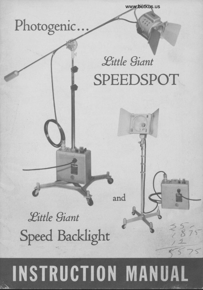
Photogenic Little Giant SpeedSpot Photogenic Speed Backlight (with schematic diagram) User manual
User manual for Photogenic Little Giant SpeedSpot Photogenic Speed Backlight (with schematic diagram). 21 pages in English. Read the original PDF, download or print a copy without registration.
21 pagesEnglish3.8 MB PDF
Loading your manual…Open PDF directly
Document details
- Brand
- Photogenic
- Model / document
- Photogenic Little Giant SpeedSpot Photogenic Speed Backlight (with schematic diagram)
- Document type
- User manual
- Language
- English
- Pages
- 21
- File size
- 3.8 MB
- Category
- Film cameras
- Document date
- Not specified in catalog
Search available document text
Find a term, then jump to its page in the original PDF. Image-only pages may not be searchable; check the PDF for exact wording and diagrams.
Page 2 · Read text
CHAPTER I
            INTRODUCTION
Section l. GENERAL
  These instructions are issued in order to assist the photographer in
the use of the Photogenic Little Giant Speedspot and Speed Backlite.
These lights were designed to fulfill the needs of the photographic
studio for highly efficient auxiliary speedlights which are small in
size and yet produce the necessary illumination to use in conjunction
with larger hieh voltage electronic flash equipment.
  Recent developments have made it possible to pnrduce this equip-
rnent through the use of smaller flashtubes. There is really no essential
difference between the Little Giant series speedlights and those
previously produced. Ilowever, the small size flashtube will not permit
the use of the higher voltage (2000 volts) circuits and nrust operate
at 450 volts. It is obvious, therefore, that the higher voltage power
supplies used on prcvlously designed equipment cannot be made inter-
changeable with the Little Giant series speedlights.
  The Photogenic Little Giant Speedspot is made in both the boom
type nnodel and the upright stand model and fulfills the need of a small
size spotlight not only for hair liehting, etc., butalso as a main source.
  The Photogenic Litrle Giant Speed Backlite provides a small size
light source which may be easily hidden behind the subject for pro-
ducing background illumination. It is provided with wings which are
easily detachable when not required.
  Both the Little Giant Speedspot and Speed Backlite will accommodate
the same snoots as are used on the Photogenic No. ?200 Little Giant
Incande scent Spotlight.
  Power supplies are availablein 100 watt-second and 200 watt-second
capacity. Each power supply is provided with a high-low switch so
that the 200 watt-second rnodel may be operated at 100 watt-seconds
and the 100 watt-second model may be operated at 50 watt-seconds.

Section 2. TECHNICAL CHARACTERISTICS
LITTLE GIANT SPEEDSPOT. Nominal Values
Output Power Rating       Low: 50 watt-seconds
  Lc100 Power Supply      High: 100 watt-seconds
Output Power Rating         Lorv: 100 watt-seconds
  LG200 Power SUPPIY     High: 200 watt-seconds
View original page 2Page 3 · Read text
www.butkus.us

 Power Sour@               - 110-120 Volt,60 cycle A.C., maximum
                             watts - 400
 Light Source                   - Type DXR Flashtube
 Modeling Lamp                - code PH100T8/108 DC Proj. CC2v Dc
                            Note: WiIl accommodate 50, Tb or 1S0 w.
                                lamps also.                                                                                                                                                                       li\'t
D.C. Voltage atfull charge  - 450
Charging time for 9O7o of.
    full charge                 - 200 watt-seconds t6 seeonds
                           100 watt-seconds t3 seconds
                         50 watt-seconds '3 seconds
Fuse                         - 1 Amp. Slo-Blo
T?iggerlng                     - Instantaneous
Phototube                     - No. 929                                           #
Flash Duration, measured
   at L/3 of peak light                                                                    #l
                                                                                          Wl   output                      - 200 watt-seconds 1/?00 second
                         100 watt-seconds 1/1000 second
                          50 watt-seconds 1/1800 second
Light Intensity                - 200 watt-seconds 5000 Beam - candle-
                          power - seconds
                                                 ' 100 watt-seconds 2500 Beam - candle-                          power - seconds
                          50 watt-seconds 1250 Beam - candle-
                         power - seconds
Color Temperatu€            - ?000 degrees Kelvln (approx.)
Lens                          - 4-L/2" Fresnel Type
   'Note: The initial charge tinn may be somewhat greater due to the
fact that a certain anrountof tine rmybe required toform the capacitors.
LITTLE GIANI SPEED BACKLIIE - Nomlnal Values
Output Power Rating        - Low: 50 watt-seconds
  LG100B Power Supply      High: 100 watt-seconds
Output Power Rating        - Low: 100 watt-seconds
  LG200B PowerSuPPlY      High: 200 watt-seconds
Power Source               - 110-120 volt, 60 cycle A.C., maximum
                            watts - 400
Light Source                   - TVpe DXO Flashtube
View original page 3Page 7 · Read text
www.butkus.us

will have a tendency to tighten the knob of the swivel and a^rrest
any further tilt.
3. After the boom arm and swivel are assembled to the stand,
mount the spotlight head on the boom arm. Befor€ connecting the
spotlieht electrically to the power supply, the flashtube and
modeling lamp should be installed in the spotlight head by re-
movins the lens of lhe spotlieht. This is best done by tilting thespotlight upward slightlv before removing the lens retaining iine.
After the lens retaining ring is removed tip the spotlight forward
while holding one hand over the lens opening to catch the lens
as it drops out. The flashtube is polarized so that it cannot be
installed incorrectly. After installing the flashtube and modeling
Iamp replace the lens and lens retaining ring.
4. The spotlieht may now be connected to the power supply and
the line service cord connected to the wall ouilet.
5. If the unit is to be used as a slave unit the No. 929 phototube
shonld be installed in the photoeye socket located on the top of
the power supply. For direct triggering a trigger outlet ls pro-
vided for connecting a trip cord to the camera. The 929 phototube
should be removed from its socket when the trip ccrd is used.
                                   I
View original page 7Page 8 · Read text
www.butkus.us


                                                                                                                                      Digitally signed by Mike Butkus
                                                                                                     DN: cn=Mike Butkus, o=Butkus camera manuals, ou=butkus.org,
                                                                                                             email=mike@butkus.org, c=US         Mike Butkus                         Date: 2022.07.12 20:03:10 -04'00'

Section 2. UNPACKING AND PLACING PHOTOGENIC LITTLE GIANT
        SPEED BACKLITE INTO SERVICE.
  a. Unpack all units calefully so as to make certain that all Fa,rts
are renpved from the packing cases. The entire unit should consist
of the following parts:
  Check
       [|    ( 1) Power Supplv Unit LG200B or LG100B
          (2) Reflector and Flashtube Assembly   D
          (3) Barn Door AssemblY    J
          (4) Socket and Cord Assembly   n
   n  (5) Stand uPrieht
      f]  (6) Stand Base
      fl   (?) No. 92e Phototube
   n   (8) PH60T6t/z/1 UoOetins lamp
                                    10
View original page 8Page 9 · Read text
b. After unpacking, all parts should be examined for any damage
which may have been caused by rough handling during shipment. lF
ANY DAMAGE 15 DETECTED,CONTACTTHE DELIVERING CARRIER
AT ONCE. CLAIM FOR DAMAGE SHOULD BE MADE TO THE DE.
LIVERING CARRIER BEFORE DESTROYING PACKTNG CASES.
  c. The unit may now be assembled by observing the following
routine:
     1. Install the casters into the stand base. Install the stand up-
     right into the base and tighten with a wrench. Assemble the
     socket and cord to the top of the stand tube. A stud for using
     the light at floor level is also provided and this should be in-
      stalled into the threaded hole provided in one stand leg.
     2. The P-H60TGy2/l modeling lamp may now be installed into    the socket provided in the socket and cord assembly and the
     reflector and flashtube assembly instatled by inserting into the
     four pin socket provided. The barn door may then be installed
    and fastened in place by means of the trvo knurled nuts,
    3. Connect the lighting unit to the power supply and the line
     service cord to the wall outlet.


                                                                     Rcflector and
                                                                  Fla;htube Assenbly


          I
                I


         Fig. 3


                                        1l
View original page 9Page 10 · Read text
www.butkus.us

       Scc?ion 3. OPERATION OF THE PHOTOGENIC LITTLE GIANT
                SPEEDSPOT.
         a. Scope. The Photogenic Little Giant Speedspot fills the need
        for a snnll, hiehly efficient spotlight to be used in conjunction with
        other large source speedlighting equipment in the photographic  studio.
          It may be used as a hair light or as a main source light in much the
      same manner as the Cat. No. ?200 Little Giant Spot which has been
     a standard incandescent spotlight used in studios throughout the
       counhy for many years. The Cat. No. ?202 snoots and Cat. No. 7206
       barn doors are also interchangeable with those used on the Cat. No.       7200 Incande scent Spotlight.                                                                            I
         b. Lens. The 4-L/2" Fresnel Lens prcvides a tight which is con-                I
        centrated in the center and less intense at the outside edge. This
       provides a very efficient main source light for so-called glamour
        or butterfly lightings.
          c. Power Supply. The power supplies for both the Photogenic Little
       Giant Speedspot and Little Giant Speed Backlite are electrically the
        sarne. The power may be turned to Hi or Lo by means of a rotary
       switch loca0ed in one corner of the power supply (See fig.  5). A       separate switch is also provided to control the modeling larnp. When
       the unit is on, the red pilot light (power) will come on, showing that
      power is flowing into the unit. The white pilot light (flash indicator)
        will also glow brightly and gradually dim as the unit reaches full
        charge. After each successive flash this light will again glow brightly
           if the unit flashe.d. If the unit fails to flash this lieht will not come
       on. In this manner it is very simple to determine if one of the units
       has failed to flash.
          d. Synchronization. The power supply is equlpped with a trip cord
       connection (trigger) which may be used to connect the unit to the
       camera synchronizer. In addition, the unit may be operated as a slave
        unit by installing a No. 929 phototube in the Photoeye socket provided
        in the top of lhs power supply. This socket is rotatable so as to take
       advantage of the best direction for receiving the light impulse from
        another speedlight:
       Section 1. OPERATION OF THE PHOTOGENIC LITTLE cIANT
              SPEED BACKLITE.
         a. Scope. The Photogenic Liftle Giant Speed Backlite provides a
       small, very efficient, speedlight source for illuminating backgrounds,
       etc. BJ the use of the ba,rn doors and No. 7202 snoots any type of
       normal background effect may be obtained.
          b. Reflector. The reflector is a 60 degree type reflector which rnakes
           it possible to flood the ba0kground  if necessary.
           c. Power Supply. See Section 3, paragraph c.
          d. Synchronization. See Section 3, paragraph d.
                                            L2


:*: .-.*u&1,..,. ;:E;,      ..,.  ...
View original page 10Page 11 · Read text
Section 5. USE OF BACKLITE WITH BOOM STAND.
        Some photographers have found that they wish to dupt the Little
        Giant Speed Backlite lighting unit to the Little Giant Boom Speedspot
        arm and special adapters are available for this purpose. In this case
        the power supply should also be the same type as that used with the
          spotlight as it provides for attaching to the stand.
          Special Power Supplies with two high voltage outlets are also
         available, on special order. These will enable the user to operate
I       two liehting units from the same power supply.
I
                CHAPTER III
                      DETAILS
         Section l. POWER SUPPLY.
         a. The porver supplies for all units are electrically similar and
         provide 450 volts direct current which is stored in the capacitor bank
          until flashed through the flashtube of the lighting unit. The 200 watt-
        second model power supply is equipped with four 525 Mfd. capacitors
        and the 100 rvatt-secord model is equipped with two 525 lvlfd.capacitors.
          b. The power source may be any 110 to 120 volt, 60 cycle A.C.
          line. By means of a transformer this voltage is increased to 450 peak
        volts which is then rectified to direct current and stored in the ca-
          pacitor bank until discharged.

                                                                                                           I Amp. Slo-Blo Fuse         Power Indicator Light
                                                                                                                         Lighting Unit
                                                                                                       Connector


                                                                                                                                     Indicator Light
                                   www.butkus.us
                                                                                                                                                  rip Cord Connection


                                                                                                                     Connection


                                                                  Lamp Switch
View original page 11Page 12 · Read text
www.butkus.us


                       Fig. 5

  c. TTiggering is accornplished electronically by the use of a No.
2D2I Thyratron tube. (See Fig. 5). This tube is easily replaced
by removing the top panel of the power supply. A safety switch is
provided which will completely de-energize the capacitor bank when
this panel is removed. (See Seryice Instructions).
  d. The Hi-Lo feature of this unit is accomplished by switching
capacitors in or out of the circuit. When the unit is switched to Lo
position onl.y one half of the capacitor bank is charged, and when
switched to Hi the entire bank is charged. When the unit is switched
from Lo position to Hi position a condition arises in which onehalf of the capacitor bank is fully charged and the other half has
no charge. As this will produce a severe strain upon the switch
contacts it has been necessary to adopt a safety measune to over-
come this. A time interval switch has therefore been provided which
will allow the uncharged portion of the capacitor bank to reach
full charge before being connected directly to the charged portlon.
This time interval is approximately 10 seconds and is automaticallyconhollbd. Therefore, when the unit is switched from Low 0o High
position there will be a ten second interval before capacitors are
ready to be discharged at full power. THE UNIT SHOULD NOT BE
 FLASHED DURING THIS INTERVAL.
                                      t4
View original page 12Page 13 · Read text
Seoi5n 2. LITTLE GIANT SPEEDSPOT LIGHTING UNIT
  The lighting unit uses a type DXR flashtube and a pHloOTg/lOg
DC Projection Lamp with CC 2V filanrcnt and double contact base. A
 cable is provided of proper length to reach the power supply unit when
 the stand is fully extended. Flashtubes and modeling lamps may be
 changed by removing the Fresnel lens of the spotlight as explained
 in Chapter II, Section lc. of this manual. The light may be focused
 from spot to flood by turning the knob located at the rear of the housing.
 Section 3. LITTLE GIANT SPEEDSPOT STANDS.
   All models of the Little Giant Speedspot are provided with air
 cushion stands in order to protect the flashtube and modeling lamp
 from damage if one of the positioning knobs is accidentally loosened.
The boom type Little Giant Speedsrlot is provided with a boom arm
 48" Iong and the following are the limits of the stand uprights:
                       Lowest Height Extended Height
   Nlodels 8200 & 8201        40"             8 ft.
    I\l0dels 8205 & 8206       40"                   I  ft.
 Scction 4. LITTLE GIANT SPEED BACKLITE LIGHTING UNIT.
  a. Reflector and Flashtube. The reflector is a 60 degree type in
which the DXO flashtube is installed as an integral. part at the factory.
If it becomes necessary to replace this flashtube it is best perforrned
at our factory in order to minimize the chance of breakage. The tube
base of the DXo flashtube projects from the lower rear part of the
reflector and must be plugged into the 4 pin socket located on the
socket and cord assembly.
   b. Socket and Cord Assembly. The socket and cord assembly is
provided with a modeling lamp socket. In order to change the modeling
lamp it is merely necessary to remove the reflector and flashtube
assembly. A 15 ft. long cable allows the power supply to be locatedaway from the subject where it will not appear in the photograph.Tilting is accomplished through the use of a multiple disc friction
tilting stand adapter.
Section 5. LITTLE GIANT SPEED BACKLITE STAND.
  The stand is a telescopic type adjustable from 1g,, to 4 ft. A stand
leg stud is provided to use the light at floor level if rlesired. Arsoa lower level adjustment bracket is available which will provide
adjustment of the light between the floor level and the top of the stand
when it is adjusted to its lowest height.
CAUTION: Whenever it is necessarT to replace flashtubes or modeling
Iamps the unit should be turned off and the lighting unit disconnected
from the power supply.
                                    15


                                                                 ei&tbiea,',.
View original page 13Page 14 · Read text
www.butkus.us

        Section 6. SYNCHRONIZATION.
          Syncluonization is extremely important and the greatest care should
     be taken in making all connections to the synchronizer cables. If
       these connections are not made in a careful and workmanlike manner
           it may result in either an intermifrent connection or an electrical leak
       between the two leads. Either will cause unreliable perforrnance. An
        electrical leak will be especially noticeable during humid weather.
       When making any connection to the trip cord the following steps should
       be observed:
          1. Cut wires of the cables to be connected as shown in fig.  6a.
            2. Strip each lead l/2" (Fig. 6a).
         3. 1'wist leads together and solder securely. Use only rosin core
           solder. Use no flux either paste or liquid. (Fig. 6b).
           4. Insulate with Scotch No.33 electrical tape or equivalent. (Fig. 6c).

            I                                                                      il
   U               a        IVG
                PREPARATION OF SYNCHRONIZER CABLE

          After the synchrcnlzer cable is prrrperly connected lt ls well to
       check the synchronization with the camera. Adiust the lighting unit
        to the same height as the carnera lens and face the light into the lens.
       The lens aperture should be opened to its fullest extent and the camera
       back removed. Looking at the lens through the back of the camera,
        operate the shutter. The flash of the light shottld then appear as a
        circle the same size as the aperture. It is best to perform this test
       with modeling lamp turned off. If the circle is flattened on the sides
        or if no light appears through the lens, the shutter is not synchronized
       with the light. Shutter contacts for this light should be the X or zero
       delay type. If the light appears not to be synchronized the shutter
        contacts should be checked by a reputable camera repair tnan.
                                             16


.,. .   ..*r.,.!;-i  ;,d4*    ..-,ii..  ...--i&riil4{L-,
View original page 14Page 15 · Read text
CHAPTER IV
                 SERVIUE
 Section l. GENERAL.
   In order that you may expect long and trouble-ftee service every
precaution has been taken in the design and manufacture of this
 equiprnent. Frequent servicing is not likely to be necessary and this
chapter is offered to assist the photographer in recognizing the most
probable cause of any difficulty wirich may arise.
   While we have gone into considerable detail in service instructions
we assume that, unless you are familiar with electronic equipment,
you will not attempt to make repairs yourself. However, these in-
shuctions will prove of assistance to a competent service man.
 Section 2. SAFETY PRECAUTIONS.
   a. Despite the extreme measures that have been taken to make this
equipment foolproof,  it must be recognized that high voltages do exist
within the power supply,, cables, and lighting units. Therefore, certain
precautions must be observed in handling this equipment.
   b. Do not attempt to change tLashtubes or modeling lamps unless
the unit has been discharged and the lightine unit disconnected from
the power supply.
   c. Always make certain that the power supply is disconnectecl  frorn
the 115 volt A.C. line before attempting to service it.
  d. When removing the top lid of the power supply, always assume
that high voltages may exist within. A safety switch has been pro-
vided to discha.rge the capacitor bank when the lid is removed, and
the operation of this switch may result in a loud report. To be doublysafe it is well to connect a rvire betv'reen the positive and negative
terminals of the capacitor bank. This will surely discharge all of
the stored electrical energy.
           DO'S AND DON'TS
DO - Turn Power Supply Unit "OFF,' when not in use.
DO - Avoid quick repeated flashing. Damage may result. The  full
charging time should be allowed between flashes.
DON'T - Permit a lighting unit cable to become frayed or loose in a
connector.
DON'T - Insert or Relnove a Flashtube unless the power Supply Unitis fully discharged.
                                 1?
View original page 15Page 16 · Read text
www.butkus.us

                 DO'S AND DON'TS (CONT'D)
DON'T - Remove the top cover from the Power Supply Unit or place
a hand near any part inside the unit until you are certain that the
capacitor bank is fully discharged.
DON'T - Insert a scnew driver or other metal object into the flashtube
socket or any electric outlet, socket or receptacle. Contact with high
voltage may result.
DON'T - Attempt to make repairs to the speedlight outfit if you are not
familiar with electronic equipment. Your dealer should be consulted
rega^rding an authorized electronic or radio service station.
DONT - Use a higher rated fuse than is recommended.
DON'T - Plug the unit lnto any senice except 110-120 V. 60 cycle
A.C. If this unit is plugged into D.C. service it may result in serious
danage to the component parts.
DON'T - Flash unit while the time interval switch ls running.

 Scction 3. TROUBLE SHOOTING
  &. General. In otder to remedy any difficulW which mieht arise it
is necessary to ipolate the component which is faulty. In order to do
this it must first be rletermined whether the fault lies in the power
supply, lighting unit, or external triggering circuit. vfitn tnis in mind,
when the light fails to flash, the following steps should be taken, in
 order, until the difficulty is located:
    1. Remove fuse cap to determine if fuse ls blown
   2. Disconnect trip cotd from trigger outlet and make contact between
   the ccnter terminal and the edge of this outlet. When light is being
   used as a slave unit another No.929 phototube should be substituted.
   3. Connect another lightine unit to the power supply.
   4. Connect another power supply to the lighting unit.
   5. Clcnnect another llne service cord to the power supply.
   If the above steps are followed the component wherein the fault is
located wlll be isolated.

Scction 4. COMMON SYMPTOMS AND THEIR CAUSES.
  A. FUSE BLOWOUT
      (1) Defective Fuse
      (2\ Defective Tlansformer
View original page 16Page 17 · Read text
(3) Defective Power Capacltor
       B. INDICATOR LIGI{TS DO NOT LIGHT (power and flash lndicator)
          .   ( 1) Burne&out No. 44 LamP
            Note: If flash indicator lamp fails it should be replaced inr
                      with a No. 44 pilot lamp or damage may result to *<i          mediately             the power supply.
            (2) glown Fuse
   .       C. FAILURE TO FLASH
 s,r'{       (1) Defective  trifi cord or synchronizer. (See step 2 under trouble
           shooting)
       ,    (2\ Defective 2D21 triggering tube (See Fig. 5).
            (3) Defective Flashtube,(See step 3 under trouble shooting).
           (4) Defective friggering Capacitor No. C-5 located in power supply.
            (5) Power Supply not charged (defective transformer or rectifier).
 'i!    D. spoNTANEous REpEATED FLASHING
  rn         (1) Flashtube reaching end of its normal llfe, especially when
 ;        heated by modeling lamp.
  trt*         (2) Defective 2D2l Triggering Tube G.
#         (3) Defective resistor in bleeder circuit
       E. SPOT.ITANEOUS OCCASIONAL FLASHING
  ::.            ( l) Line disturbance caused by other electrical devices
                     ( 2) Defective trip cord
            (3) Defective 2D2l triggering tube
       F. MODELING LAMPS FAIL TO LIG}fT
            (1) Defective modeling lamp
            (2) Modeling lamp improperly inserted ln socket
            (3) Defective modellng lamp socket
            (4) Defective modeling lamp switch.                                         l


        worthy of a special discussion.
                                         19li.i'


.

                                                                                         aLE-r    r-!lf-'f
View original page 17Page 18 · Read text
www.butkus.us

(1) Repeated flashing as mentioned in D (1) of Section 4.
  As a flashtube nears the end of its normal life it may tend to flash
at regular intervals with no apparent reason. This is caused by the
fact that after the tube has been flashed many times, the voltage at
which it may become self conductive decreases. It then will flash
as soon as the voltage reaches this critical point. This condition is
further aggravated by the heat of the modeling lamp. It is also more
likely to occur in equipment which, due to its physical size, cannot
be well ventilated. The life of the flashtubes in some instances may
be prolonged by interchanging tubes between various units. Also, if
the modeling lamp is turned off at intervals it will allow the tube to
cool to a point where it will correct itself. While spontaneous flashing
from this cause is more apt to occur in old hrbes, it may also occur
at times in new ones.
(2) Failure to flash reliably as mentloned in e (3) of Section 4.
  Flashhrbes sometimes fail to flash when the modeling lamp has
been turned on for a considerable length of time. This is usually
caused by the triggering Pulse being dissipated through the glass
envelope of the modeling lamp lnto the filament circuit..This occurs
in eqnipment employing the PH60TOy2/l modeling lamp, but not
in spotlights which employ projection lamps. However, it is well to
note whether or not the corrccf modeling lamp ts being used. The
PH60T6/z/1 modeling lamp has a 2" long filament suspended through
the center of the br:lb, and is the successor to the 60T6Yz/I lamp
which had a cluster type filament. This older cluster type filament
modeling lamp caused a great deal more of this difficulty than the
present one. However occasionally the newer type will also cause
trouble when the filament sags toward one side of the bulb, and in
this case it can sometimes be corrected by reversing the modeling
lamp in its socket.
 (3) Static Electricity
  When elechonic flash equipment is used in a carpeted studio it
will sometimes be noted that the lights will flash whenever they are
touctred. This is due to the fact that when a person walks across a
carpet his body will accumulate a cha.rge of static electricity. Upon
touching the lamp or camera some of this static electricity may be
discharged, causing the lamp to be triggered. This of course is annoying
but it is neither dangerous nor harmful either to the person or the
lighting equipment. The condition is usually apparent during thewinter months when the humidity is low and may sometimes be cor-rected by the use of a humidifier to introduce additional humidity
 into the mom.
 (4) Modeling Lamp prematurely burns out.
  This is usually an indication that the line voltage is considerably
higher than the normal 115 volts. This condition may be corrected by
using a voltage regulator. An automatic voltage regulator should not
be used as it is not applicable to electronic flash equipment. A manual
                                  20
View original page 18Page 19 · Read text
type voltage regulator should be used. However it is necessary to use
a regulator equipped lvith a voltmeter,, such as the No. T1404v voltrol
 unit supplied by Photogenic Iflachine company and available through
 the dealer from whom you purchased this equipment.
 (5) iti-Lo Switch.
  As mentioned earlier in these inshuctions, when the unit is switched
from Lo to Hi an interval of 10 seconds should be allowed before
 flashing. If flashed drring this period it may result in damage to theswitch contacts as it may cause the timer srvitch contacts to stick.
 If this o@urs damage will then result to the main switch and a report
may be heard during switching. If the main switch is damaged it nray also result in the unit producing the same output on low as it does
 on high.
 (6) CAUTION.
    It must be rcmembered that all electric flash equipment uses voltages
whiclt are dangerous. AII Photogenic Speedlights are carefully designed
to be safe when used in accordance with the instructions. If you a^renot fully familiar with electronic equipment, it is essential that you
contact an authorized service man or your dealer if service is nec-
essary, calling his attention to these instructions.
 (7) FactorJ Repair.
    If at any time this equlpment fails to operate properly and you, or
your service man, a^re unable to determine the cause, The photogenic
Machine comparly maintains a repair department which is equipped to give fast, competent service.
  When it is necessary to return any equipnrent to the factory for
service it should be accompanied by a complete explanation of thedifficulty which exists. This will greatly assist our repair department
in expediting the return of your equipment.
   If argr doubt exists as to whether the power supply or the lighting
 unit is defective, both should be returned.

             PARTS LIST
LIT'TLE GIANT SPEEDSPOT LIGIITING UNIT
I-3   Modeling Lamp - No. 100T8/108 DC
P-1  Connector - AN-3L06-22-24P
V-3  Flashtube - Type DXR
T-2   TTigger TTansformer - Part of V-3
LTTTLE GIAI{T SPEED BACKLITE LIGHTING UNIT
I-3    Modeling Lamp - No. PH6OT6Y2/tP-1  Connector - AN-3106-22-24p
V-3  Flashtube, Type DXO - Fastory Mounted in Reflector
T-2   Ttigger Ttansformer - Part of V-3
                                  2l


                                                                               -'-,;xe' .  .,,: *ri;*i:.+#:".:r
View original page 19Page 20 · Read text
www.butkus.us

                        PARTS LIST
   LCr2OO. LG.2OOB, LG.IOO Ard LCT1OOB POWER SI'PPLIES FOR
   LITTLE GIAI{T SPEEDSPOT AND SPEED BACKLITE
   C-1  Capacitor, Electrolytic  - 525 MF. 450 VDC
   C-2  Capacitor, Sanre as C-l
   C-3  Capacitor, Same as C-l
   C-4  Capacitor, Same as C-l
   C-5  Capacitor, Fixed Paper - .5 MF. 600 VDC
   C-6  Capacitor, Fixeci Paper - .25 MF'. 4O0 VDC
   C-7  Capacitor, Ceramic - 500 MMF. 500 VDC
   CR-1 Selenium Rectifier - 65 Ma, 3 type 8J1
   CR-2 Selenium Rectifier - 65 Ma, 3 type 8J1
    F-l   Fuse - 1 Ampere - Type 3AG Slo Blo
    I-1   Flash Indicator Lanrp - No. 44
    l-2    Pilot Lamp - No. 44
    J-l    Connector, 3 wlre Hubbell - No. ?486
   J-2   Connector, AN-3L02-22-245
   J-3   Connector, ?5-CL-PCIM
   R-1  Resistor - 3.9 Ohms - 2 watt
   R-2  Resistor - 500 Ohms - 10 watt   R-3  Resistor - 470 K-  l watt
   R-4  Resistor - 100 K - l/2 watt
   R-5  Resistor -  15 K - l/2 watt
   R-6  Resistor - 100 K - l/2 watt
   R-7  Resistor- 1 M - l/2watt
   R-8  Resistor-470 K- l watt
   R-9  Resistor - 500 Ohms - 10 watt
   S-1  Switch - SPST - Toggle
   S-2  Switch-2Pole,
                3 Position, Ceramic Wafer No. A305
   S.3   Switch - DPST - Spring Operated Safety Switch
   S-4  Switch - SPST - 10 Second Time Delay Switch No. 831G1
   T-1   Transformer, Porver - RK-987
    v-l    Electron Trbe - Type 2D2L, Thyratrcn Ttigger Tube
   V-2  Electron Tube - Type 929, Phototube
      I{OTE: C-2 & C-4 omitted ftom LGr100 & LCr100B Power Supplles.
    R-9 omitted from LCr200 & LCr200B Power Supplies.
'     Wben ordeing replacement palts, please specily tbe model number   and serial nu*b.,     ttte equipment, as utell- as-ibe part numbet and
    desciptron as given                    "1 in the aboue list. This u,,ill minimize enors and
    insure tbat tbe cortect replacement paTt uill be sbipped.


                                   22
View original page 20Related documents and language editions
From the M. Butkus archive. Original publisher and archive notices are retained.
Check the model and edition against your equipment.
PDF verified 2026-10-10.