Film cameras
Photostat camera User manual
User manual for Photostat camera. 30 pages in English. Read the original PDF, download or print a copy without registration.
30 pagesEnglish3.8 MB PDF
Loading your manual…Open PDF directly
Document details
- Brand
- Photostat
- Model / document
- Photostat camera
- Document type
- User manual
- Language
- English
- Pages
- 30
- File size
- 3.8 MB
- Category
- Film cameras
- Document date
- Not specified in catalog
Search available document text
Find a term, then jump to its page in the original PDF. Image-only pages may not be searchable; check the PDF for exact wording and diagrams.
Page 3 · Read text
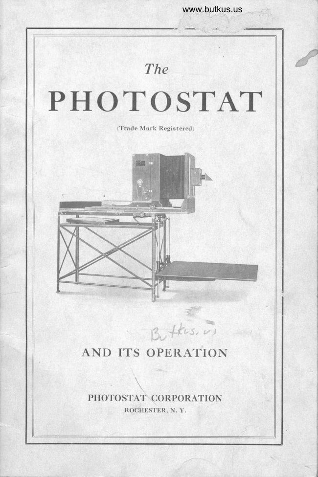
Manual of the Photostat
 P hotographic Copying Machine
 l-l-tHE PHOTOSTAT is a simple and practical machine for the rapid
                                                             consists of a   I  production of copy by means of photography.  It ^  large camera rvith a rnagazine for holding a ro11 of sensitized paper
and r'vith compartments for developing and fixing. This asscmbly is
mounted upon a stand, to thc front legs of which is attached a movable
subject holder. The equipment also includes a simple device for
mechanicall). focusing the machine to any desired size of copy.
   The Pnorosrar is loaded with a roll of special sensitized paper
upon which the subject is photographed through a lens with prism
attached. No intermediate negative is required, thc copies being
produccd in correct position. As the phobographic paper copres are
made they are cut off, developed and fixed right in the machine itself,
no dark room being required. \\rhen washed and dried the copies
are all ready for usc.
   Printed or written documents, drawings, blue prints, records,
maps, fabrics, smali tools, inachine parts, etc., may be copied in a few
minutcs at a cost of a ferv cents. The mechanical devices for quickly
focusing and handling the machine render it so simple that anyone
can learn to operate it with an hour's instruction. No previous
knorvlcdgc of photography is necessary. Perfect copy is produced
with speed, accuracy, and convenience.
Construction
   Thc Pnorosr.q.r is of metal construction. Every detail has been
carefully worked out. Thc mctals uscd have been sclected and tested
                                                                                                                                                                                                                                 2for strength, durability, and to mect the special requiremcnts. In                                        'r.}
design and workmanship the Mr.;rar PHorostar  is a finished product.
It embodies thc results obtaincd from an experiencc of over ten years
in consLruction, and thc opcration of PHorosrars under actual riork-
ing conditions. The machine is handsomely finished in enamel u'jth
trimmings heavilv nickeled.
   The Anastigmat Lens used on the Puorosrar is the best qualitv
obtainablc. A11 working parts are standardized and easily replaced
if needed.
Main Parts
  A detail description of all parts of the PHotostat, showing their
location, use, and mcthod of operation is given in the text and shown
in the illustrations of the Manual. A ro11 (250 ft.) of sensitized papcr,
wjth chemicals for developing and fixing, is included with each
Pnorosrrr for the purpose of demonstration and instruction.
View original page 3Page 4 · Read text
www.butkus.us


                MANUAL OF THE PHOTOSTAT


                                  Digitally signed by mike
                           butkus
                         DN: cn=mike butkus,mike         o=orphancameras, ou=29,
                            email=mike@butkus.org,
                        c=US
                              Date: 2019.09.02 21:08:31butkus  -04'00'


                         Fig. l-No. 1 Photostat.with Engineering Board
  A. Magazine.                          J. Fixing Tray  B. Camera Frame.                    K. Stand.
  C. Bellows.                           L. Subject Holder.
  D. Camera Bed.                    M. Focusing Scales.
  E. Front Frame                     N. Ground Glass Screen.
  F. Lens Box.                        O. Rotary Handle on Developing Tray,
  G. Lens and Prism.                         shown in vertical position ready to
  H. Color Screen Handle.                          receive prints.
   I.  Developing Tray

    The main parts of the PuorosrAr are as follows:
 Magazine-((A" Fig. 1
    The Magazine ts hinged to the Camera Frame, which itself is
 mounted upon the Camera Bed. It contains a light-tight compart-
 ment with a Metal Box for holding roll of Sensitized Paper; Rubber
  Rollers for holding the Paper in position for exposure and to wind
  it into the Developing Tray; Lever Knjfe for cutting off the exposed
  sheet, and a Dark Curtajn when needed for protecting the Sensitized
  Paper from exposure. On the operating side of the Magazine are
  arranged Handles and Levers for operating the Ro1lers, Knife, and
 Dark Curtain.
View original page 4Page 5 · Read text
MANUAL OF THE PHOTOSTAT

                                           1Camera Frame-"B" Fig.
   This supports the Magazine and rear end of Bellows, "C" Fig' 1'
The Developing and Fixing (Hypo),Trays rest on the floor of Camera
Frame. It is racked forward or backward upon the Camera Bed
to bring into focus.


                                       1Camera fiafl-((l)" Fig.
   The Camera Bed rests jn guides upon the Stand. Attached to
the front end is the upright Front Frame, "E" Fig. 1, which supports
the Lens Box, "F" Fig. 1, and also the front of the Bellows.
Lens and Prism-"G" Fig. 1
   The Lens and Prism are firm1y attached to the removable Metal
                                                                and' PrismFront Plate, "A" F'ig. 4, of the Lens Holder. The Lens
sh,ould neaer be taken apart or remoaed from the Front Plate, as they are
tested and adjusted for correct focus before shipment. (See Focus
Scar-os, Page 4.)
   In the Lens Box is a Color Screen which is used in conjunction
with the Lens when subjects in color are copied. It is operated by
Handle, "G" Fig.4.


                I.ig.2-M^g^zine Showing Operating Handles and Levers
       A. Lever for separating Winding Roiiers.
       B. Handle for Winding Rollers.
       C. Release Key.
       D. Cutting Knife Lever.
        E. Shifting Pin for Whole or " Ha1f " Size Prints.       F. Dark Curtain Knob for operating Curtain.
       H. Wheel for racking Cameri, with-Milled Head Lock.
View original page 5Page 6 · Read text
www.butkus.us

                 MANUAI, OF THE PHOTOSTAT4
Deueloping and Firing (Hypo) Trays
   ((I"       Fig. 1 and "J" Fig. |                    _
   These'Trays test ott the floor of the Camera F'rame, di19-gllVinder                                                   ((N"               '{,[,agazine.                                                               Fig. 3.               A nickeled Copper Protection,and back of
is placed under tlie rubber-lined Hypo Tray, "J" F'ig' 1'

                            1Stand-((K" Fig.
   The Stand supports the entire apparatus. Attached to the front
are the Guid"e Rods, "P" F'ig. 3, foa supporting the Subject Holder
and the gearing for'raising or lowering the Holder to bring subject
into focus.

                                           1Subiect Holder-"L" F'ig.
                                                      The   Two styles of Subject Holders are made for the Pnorosrar.
Book Holder, Fig. 11, with glass cover is used to hold. books,_valuable                                                                                                         il". used to holdpapers, erc. ffe Uige Engineering Board, trig. 1,
                                                                                 easilSrdrawitrgs, blue prints, etc. They are interchangeable and
attached bo the Stand.


                                                   www.butkus.us

            Ftg. &-No. 1 Photostat wlth Ma$azine swung open' Dark Curtain down
 A. Socket for fnterchangeable Handle to    I. Prism attached to Lens.      rack Camera Bed.                         I. Lens Shutter Handle for exposing.
 B. Socket for Interchangeable Handle to    i(. Aluminum Hinged Cover on Develop-
         lift or lower Subject Holder.               ing Tray. C. Wheel for locking Camera Bed.        L. Magazine Catch.
 D. Interchangeable-Handle  for winding.   M. Slid-ing Shelf to support Hypo !ruy.
 E. Pointer on Stand.                  N. Coopei Protection placed under Hypo
 F. Pointer on Subject Holder.                   Trav.
 G. Wheel for ra6king Camera, with   o. Rubber Lined Hypo Tray.
       Milled Lockins Head.                 P. Guide Rods for Subject Holder.
 H. Pointer on Came-ra for Focusing.
View original page 6Page 7 · Read text
MANUAI, OF TIIE PIIOTOSTAT
Focus Scales-"M" Fig. 1
   The Focus Scales are attached to Camera Bed and front leg of
Stand. When Pointer, "H" Fig. 3, on Camera, and Pointer, "F"
Fig. 3, on the subject Holder, rest upon corresponding numbers on
their respective Scales, the Pnorosrar is correctly focused. Neaer
change the positions of the numbers on l,he Focus Scales or tahe the Lens
apart, as you will get the focus out of adjustment. Before shipment
each PnorosrAr is properly tested and the numbers on the Focus
Scales carefully set into place and calibrated with the Lens. Ary
change of position will throrv the machine out of mechanical focus.
 Photostat Paper
  IMPORTANT, PHOTOSTAT PAPER SHOLILD ALWAYS
BE USED II{ THE PHOTOSTAT.
  PHOTOSTAT PAPER is a highly specialized product. It has
taken many years of manufacturing experience and costly experiment
to bring Photostat Paper to its present high standard of quality.
    It is strictly an AMERICAI{ PRODUCT. Both the raw stock
from which it is made. and the soecial sensitized emulsion with which                            -byit is coated, are manufactured    the Eastman Kodak Company,
expressly and. erclusively for use in the PHorosrar. An unli,mi,ted
supply of paper of unif orm quality is thus assured at all times.
  No other paper compares with PHOTOSTAT PAPER in quality,
flexibility, or beautl' of the finished copy.
     If found to be defective in manufacture, any ro11 of Pnorosrar
PapBn will be reolaced free.
   Puorosrer Parrn, of standard weights and wiclths, is put up in
rolls which fit into the Metal Box of the Puorosrar.
   The Standard Grades manufactured are:
   Pnorosrar Parun, Grade A. Standard Light Weight Stock,
Roll 350 ft.
   Pnorosrar Parnn, Grade B. Standard Medium Weight Stock, 1//'.-"/LRoll 350 ft.
   PHorosrar PanEn, Grade D. Glossy Surface Emulsion, Roll
250 ft.
Photostat Deueloping and Fixing Chemicals
   Puorosrar Chemicals are manufactured by the Eastman Kodak
Company expressly for developing and fixing Pnorosrer PapBn.
   These are put up in convenient packages with full directions for
mixing solutions.
   Only hi,gh grode tested. chemicals should be used to properly develop
and fix PHorosrar PapBn.

Assembling
   Unpack Pnorosrar carefully from the boxes and crates in which it
is shipped so as not to injure or deface it.  The Lens and Prism,
View original page 7Page 8 · Read text
www.butkus.us


               MANUAL OF THE PHOTOSTAT


                 Fig. 4-No. I Photostat showin! Front Fralne and Lens Assembly
 A. Removable Front Plate to which E. Clamps supporting Lens Holder.      Lens and Prism are attached. F. Spring Clips.
 B. Collarfor operatingLens Diaphragm. G. Handle for operating Color Screen. C. Lens Holder, supported by Front H. Lever for making Exposure.                         "                                            I. Prism, facing Sui:jeci Holder.    Frame.
 D. Spring Catch for holding F'ront Piece J. Stop Coilar.        in place.
 packed in a separate container, will be found in large packing box with
 some other parts. The Magazine, BeIIows, Front Frame, Lens Box,
 and Camera Frame are all assembled and mounted upon Camera Bed
 before shipment.
   To assbmble Plrorosrar follow instructions carefully and in order.
     First loosen Wheel, "C" Fig. 3, by turning to 1eft. Then slide
'Camera Bed upon Stand from the front by placing the back end of the
 Bed in the guides and pushing it back into the gears on the Stand.
 Use great care to see that gear wheels on stand engage w'ith rear tooth of
 each rack; so they ui,ll be in proper mesh, to run smoothly. Insert Inter-
 changeable Handle, "D" Fig. 3, in SockeL, "A" Fig. 3, and rack Bed
 v/ay back. In this position the alignment of Camera Bed with Stand
 will show whether or not the gear wheels have engaged properly. If
 engaged correctly rack Camera Bed forward to about center of Stand.
 Level Prrorosrer, if necessary, by means of the cap screws on the
 feet of Stand.
    Release Catch, "L" Fig. 3, and swing open Magazine. Pull back
 Sliding Shelf, "M" F'ig. 3, and put metal support blocks on top of
 Shelf, "M", and under back of floor of Camera Frame. Bolt blocks
 in place through holes provided, and fasten underneath with nuts.
 (B1ocks, bolts and nuts shipped attached to Camera Frame.) Place
 Metal DeVeloping Tray, Fig. 14, in guides on floor of Camera Frame
View original page 8Page 9 · Read text
MANUAL Or. THE PHOTOSTAT                    7
and push forward, as far as possible, directly under Magazine when
                                           (shipped detached inclosed. Attach small Handle, "A" Fig. t4tray), to outside of Tray so it will hang aertically doun when the
Rubber Rotary Paddles, "D" Fig. 14, are in horizontal' posttton.
Paddles must be hori.zontal to allow sheet when wound down to pass
freely into Developing Tray, Fig. 14. Put removable light-tight cover
over Developing Tray. See that it fits closely with splash-guard near-
est Hypo Tray. Place nickeled Copper Protection, "N"  tr'ig. 3, onShelf, "M", just back of the Developing Tray and put Rubber
Lined Hypo Tray, "O" Fig. 3, in it.  Push both Hypo and Developing
Tray way forward into place, so that sheets will feed properly into
and through them.
  To attach Subject Holder, engage thumb screws in slots in the
Brackets on Guide Rods, "P" Fig. 3, and 1et Holder down until dowel
pins fit into holes provided. Tighten thumb screws firmly.
   The Lens and Prism are firm1y attached before shipment to the
Removable Front Piate, "A" Fig. 4.  Slide Front P1ate, "A", into
grooves in Lens Box and fasten in place with Thumb Screw. When
removing Lens for safe keeping slide F'ront Plate, "4", o1tt, but neaer
                                   (See LnNs exn Pnrsu, Page 3.)detach Lens from thi,s Front Plate.
  The Sensitized Paper, made especially for the Pnorosrar by the
Eastman Kodak Company, is wound in rolls (350 ft.). To load
Magazine, swing it open, trig. 3, and raise Dark Curtain to top by
turning to left Curtain Knob, "F"' Fig. 2. Remove door in top of
Magazine by inserting fingers in holes in door, pushing door upward,
and pulling outward. Take out Metat Box found inside. Unpack
ro11 of Sensitized Paoer and olace ro11 in Metal Box in Dosition so
that Paper, as unwound, will feed out oaer.the Lop of rott f rom the back.


                    www.butkus.us


  Fig. s-No. I Photostat showing Lens Lowered for making "Half" Size Prints, MagazirJ.e                  swung open showing Curtain lowered half way
View original page 9Page 10 · Read text
www.butkus.us

                  ITANUAL OF TIIE PIIOTOSTAT
Unwind about two feet of black protecting paper, allowing it to hang
                                        stamped with words,over the front of the Box. (Front of Box is"Pat. Applied For.") Place loaded Box in Magazine, Fig. 7, as far
back as it will go. Replace door, Fig. 8, leaving black paper hanging
over roller at top of door. Be sure the Paper runs from Box over
roller wjthout wrinkles. Separate Rubber Winding Rollers at bottom
of Magazine by turning up Lever, "A" Fig. 2. Fit black paper be-tween Ro1lers, pulling end down, Fig. 9, until it lies flat and true
between Rollers. Close Rollers by turning down Lever, "A"'  The
paper is thus held firmly between the Rollers and should run smoothlv
without wrinkles. Close Dark Curtain by turning Knob, "F" Fig. 2,
to right as far as it will go. While MTgazine is sti1l swung open, wind
down black paper with Handle, "B" Fig. 2, untii the union of the
black paper and white, Sensitized Paper, comes in view. Handle,
                                                              Release"B", is freed bo allow winding by a slight pressure of the                                           pressing down Knife Lever,Key, "C" Fig.2. Cut black paper off by                         as it will go. Make a clean cutting stroke"D" Fig. 2, to Left as far
and be sure the Lever "D" returns to its original upright position.
This is important, for the knife blade may otherwise block the slot
                                                                     (Seethrough which the Paper is wound jnto Developing Tray.
Cautions, Page 19.) Remove black paper and close Magazine.


                                       Illustration A
Loading With Namow Paper
   Each width Sensjtized Paper requires a separate size Metal Box.
The narrow Metal Box, when loaded, is placed in the Magazine and
exactly centered by means of the centering guides there. Move guides
up on both sides of Box and fasten firmly so Box is held in exact
center. Any width of Paper, up to the fu1l width, may thps be used
in the Pnorosrar.
View original page 10Page 11 · Read text
MANUAL OF THE PHOTOSTAT
Dark Curtain
   To completely close Dark Curtain, to protect Sensitized Paper,
 turn Knob, "F"' Fig. 2, to the right as far as it will go. To completely
 open Curtain, to expose full sheet of Sensitized Paper, turn Knob,
 "F", to the left as far as it will go. Different lengths of Sensitized
 Paper, up to fu11 sized sheets, may be exposed by opening Dark
 Curtain more or iess (Illustration A). For convenience in determining
the size to be exposed, there are numbers cut in the dial of Knob
 "F". By turning Knob, "F", to one of these numbers the Dark
 Curtain will be lifted and a length of Sensitized Paper exposed, which
measures in inches corresponding to the number selected. F or
example, when set at 14 on the dial, 14 inches of Sensitized Paper
 will be exposed.
 Sizes of Copies
    Different lengths of Sensitized Paper may be wound down and cut
 off, but for convenience a device is arranged to automatically stop
the winding so that uniform sizes, of full length, or so-called "ha1f"
length, may be made. To do this the Shifting Pin, "E" trig. 2, is


                                                 .     Fig. 6
pulled out and moved. sideways until it drops into the hole in the plate
which is marked with numbers that determine the length to be cut.
For example, when set at t4 on Model No. 1 Pnorosr,q.r, the Winding
Handle. "8" Fig. 2, wlll be automatically stopped when a copy 14
inches in length has been wound off, and when set at 6% it will be
stopped when a "ha\f" sheet (6% inch copy) has been wound, and
similarly for the other model Pnorosrars. In makinq "ha\f" sheets
View original page 11Page 12 · Read text
www.butkus.us


IO             MANUAL OT THE PHOTOSTAT
the Prints, although uniform, are not quite full half sizes, as some of
the Paper,..must be held between the rollers. Should either hole be                                   ('E",closed so that the Shifting Pin,      does not drop into place, separate
the rollers by lifting Lever, "A", and turn Winding Handle, "8",
until the Pin, "8", drops into the hole. Then close the rollers again
by turning down Lever, "A".  In operating, the Winding Handle,
"B", rnay be turned freely without fear of overwinding, as it will be
automatically stopped according to the set of the Shifting Pin, "E".
Arranging Subjects
   Place the subject to be copied in the center of the Subject Holder.
To arrange subject on the Book Holder, release catches on side and
open glass, as shown in Fig. 11. Place subject in center and close
glass top so that it is locked. When copying from a book the Scale
Chart covering Holder is removed and the movable boards separated
sufficiently to a1low the binding of the book to drop between them.
With the Engineering Board, subjects may be held flat by a thin
sheet of clear glass, or by thumb tacks. The Focusing Charts on
the Subject Holders are used in connection with the Focus Scales,
"M" Fig. 1, to determine the focus and area of Sensitized Paper used.


                                          www.butkus.us


                                           Illustration B
Mechanical Focusing
    Insert Interchangeable Handle, "D" tr'ig. 3, in Socket, "A" tr'ig. 3,
unlocking Camera Bed by loosening Wheel "C" F'ig. 3, and rack for-
ward Camera Bed until Pointer, "E" tr'ig. 3, coincides with the center
line of the plate on Camera Bed marked "C. 8".  The marker "C.B."
is to locate the Lens above the center of the Subiect Holder. Lock
Camera Bed again with Wheel, "C".
View original page 12Page 13 · Read text
MANUAL OF THE PHOTOSTAT                            II
   The Lens Box, "C" Fig. 4, may be moved up or down on the
Front Frame by relgasing the Clamps, "E" Fig. 4. To lower Lens
Box on Model No. 1 Pnorosrar loosen both thumb screws on Front
Frame, lift Spring Clips, "F" Fig. 4, off pegs, slide down to Stop
Collar, "J" Fjg. 4, and fasten. Lens Box on Model No. 3 PrrorosrAr
may be raised or lowered on Frame by pushing in and turning
thumb screw.
    Insert Interchangeable Handle, "D" Fig. 3, in Socket, "B" Fig.
3, and crank Subject Holder until Pointer, "F" tr'ig. 3, on Holder is
opposite the desired number of Focus Scale on leg of Stand. Rack
the Camera by turning Wheel, "G" Fig. 3, until Pointer, "H" Fig. 3,
is on the corresponding number of Focus Scale on the Camera Bed.
The Knurled Hand Wheel on the inside of Wheel. "G". locks Camera
in position. The Pnorosrar will now be in exact focus, as the Focus
Scale numbers of each machine are carefully set in place and calibrated
with its Lens before shipment js rnade from the factory.
   Direct the Lens squarely towards the cross in the center of the
Focus Chart on Subject Holder. To determine exactly the correct
position of Prism, "I" Fig. 4, proceed as fotlows: Unlock and swing
open Magazine, Fig. 3, and set the Ground Glass Screen-which is
included with each Pnorosrar-into position at back of Bellows.
Fig. 12. Pegs on bottom of Ground Glass Screen fit into holes jn
lower cross piece of frame back of Bellows, and suitable catch is
provided at the top. Open Lens wide (see LBms OpnNrNc, Page 22)
and open Shutter by raising Handle, "J" Fig. 3. Loosen small binding
screw on back of Prism, "I", and turn the Prism until the cross marked
on the center of Ground Glass, exactly covers the image in the Glass
of the cross in the center of Chart. Tighten binding screw to hold
Prism securely in place.
  To properly focus a subject place it central on Subject Holder.
The Focus Chart on Holder is divided into rectansles marked with
red lines, and numbered to correspond with Focusing Scales. The
number on the rectangle, within whjch subject lies, determines the
size to which rt rr,ay be copied. Note the number of thjs rectangle,
rack Camera and wind Holder until the Pointers on each are oooosite
corresponding black numbers on Scales. The subject will then-be in
eract _focus. It will be noted that the areas of the rectangles, num-
bered 14 on X{odel No. 1 PnorosrAr, and 22 on Model No. 3
Pnorosrar are exactly equal to the full size sheets of the respective
machines, so that if focused on these numbers, subjects lying within
these rectangles rvi1l be copied to original size. An enlarged copy of a
subject is made by raising the Holder and racking back the Camera
correspondingly. A reduced copy is made by lowering the Holder
and racking forward the Camera correspondingly.
   In order to not waste Sensitized Paper, note that the whole area
within the rectangle used may be covered by one or more subjects.
   To focus for "half " sheets, lower Lens Box way down, Fig. 5, which
brings Lens on a line with center of "half" sheet of Sensitized Paper
upon which copy is to be made. Lower Dark Curtain half .y21. (see
Danx CunrArN, Page 8), and drop Shifting Pin, "E" Fig.2, into
View original page 13Page 14 · Read text
www.butkus.us


I2             MANUAL OF THE PHOTOSTAT
proper hole (see SrzBs or Coprns, Page 9). Place subject within
iectangle indicated by broken red lines on Chart, and raise or tower
Holdef to corresponding red, nurnb.er on vertical Focusing Scale on
Stand. Rack Camera to corresponding black number on horizontal
Scale, as in making fu1l size sheet. Red' numbels on vertical Scale
are used only when Lens Holder has been lowered way down. En-
larged or reduced copies are made on "half" sheets by setting to red
numbers on the vertical Scale, and to corresponding black numbers on
the horizontal Scale, as above explained.


                          Fig. 7-Loading Paper Box in Magazine
   "Ha1f" size, or other intermediate sizes, may also be made byleaving Lens Box way up, as in making fu11 sheetl In this case
                            placed in a neutral position between theShifting Pin, "E" Fig. 2, isholes ahd Dark Curtain is lowered to cover portion of Sensitized
Paper which is not to be exposed. In such cases the subject should be
placed upon the side of Holder nearest the Stand and Pointe., _".F"
Fig. 3, placed on the black nurnbers on the vertical Scale as in making
full sheets.
Ground Glass Focusing
   The mechanical focusing by Scales is designed for generat use, but
should it be desired to focus subjects rvhich do not come within the
range of the Subject Holder, the Ground Glass Screen may be used.
To focus with Ground Glass Screen, turn down Dark Curtain to pro-
tect Sensjtized Paper, and swing open Magaztne. Place Screen in
position as previously explained, and rack Camera with Wheel,
"G" Fig. 3, until in focus, as shown by the Ground Glass.
View original page 14Page 15 · Read text
MANUAL OF TIIE PIIOTOSTAT                       r3


                            Fi€' 8-Renlacif,                                                   Yf, :?"lff."'""
  A large tracing or drawing may be copied by hanging it on a watl or
screen, and turning the Prism 90 degrees to a vertical position, Fig. 15.
   Subjects may be copied to desired scale by focusing wjth a foot
rule held on the Ground Glass. This is very convenient when doing
any drafting or engineering work where enlarging or reducing to
scale is desired.
   By removing Prism altogether (not advised-see LnNs eNn Pnrsu,
Page 3), a subject may be placed in front of Lens and focused as in
ordinary photography. Negatives in reverse may thus be made
either on Sensitized Pp.per, or on glass plate in a Plate Holder, which
may be obtained for the purpose.
Lens Openings
   Around the center of the Lens is a movable Ring, "B" Fig. 4,
which operates the Diaphragm. By turning this Ring, "8", the open-
ing in the Lens is enlarged or decreased, thus admitting more or less
light, as the case may be. When set at largest opening the greatest
amount of light is permitted to pass through the Lens. Each larger
number on the scale decreases the amount of light by one-ha1f, but
increases the sharpness and clearness of the copy. Thus, opening at
stop No. 22 adrntts only one-fourth as much light as opening at stop
No. 11, and consequently requires four times as much time in making
exposure. The highest quality of Anastigmat Lens is used on the
Pnorosrer.
View original page 15Page 16 · Read text
www.butkus.us


r4             MANUAL OF THE .PHOTOSTAT


                     Fig. 9-Pulling Paper Flat and True Between Rollers
Color Screen
   The Color Screen is used only when the subject to be copied is in
color, such as blue, purple, ye11ow, or other combinations of colors.
Blue'prints, purple typewriting, colored lithographs, etc., are readily
cooied bv use of the Color Screen. The Screen is thrown on or off
by moving the Handle, "G" Fig. 4, the Screen itself being inside the
Lens Box, "A" Fig.4, directly back of the Lens.
  The time of' exposure will vary according to the color or
combination of colors of the subject. With a little experience on


                       www.butkus.us

                   FIG. lo-Shifting Pin Being Moved Sideways
                                  Frorn Hole to Hole
View original page 16Page 17 · Read text
MANUAL OI' THE PIIOTOSTAT                      r5
            this class of work perfect results are obtained, the subjects being
           reproduced in shades of black or gray, according to the relative color
            values of the originals.
             Quick exposures may be made when copying black and white
             subjects, but when the subject is in color and Color Screen used, the
           exposure should be lengthened from f.ae to ten t'irnes with the same
          Lens opening. With color screen stop 16 may be used for copying
           small subjects, but for large subjects stop 32 should be used. The
           length of exposure with color screen may be greatly reduced if the
             light is increased. For example, double the amount of light and the
           time of exposure willbe reduced approximately one-half.
          Lighting Equipment
            The PnorosrAr may be operated by using natural light to illu-
          minate the subject, but it is customary to use electric light for the
            purpose, as a more even and uniform illumination is given, and quicker
         and more satisfactory results obtained. Electric Lighting Outfits
           are manufactured expresslv for use with the Pnorosrar, and we


                                             Fig. ll-Placing Subject on Bookholderf          recommend. them. When ordering Electric Lighting Outfits please
            give us the voltage, and whether direct or alternating current is used.
                If alternating, state the frequency of the current.
            The Electric Lighting Outfit should be set up and arranged so as
             to throw the most even distribution of light over the subject. Several
            Suggestions for arrangement of lights are shown in Fig. 15, Fig. 16,
             Fig. 17, and Fig. 18.
View original page 17Page 18 · Read text
www.butkus.us


IO             MANUAL OF THE PHOTOSTAT
    In placing the Pnorosrer and Electric Lighting Outfit, care should
be taken to see that the electric light, or any other bright side or rear
1ight, does not shine upon the Developing and Fixing Trays. If
natural light is used the Puorosrar should be placed facing a window,
but so that the sun will not shine directly upon the subiect.
Instructions For Operating
   Prepare the developing and fixing (hypo) baths, as directed on the
packages, and put them in their respective Trays. Fill Developing
Tray so solution just covers the upper guides. Place the subject on
the Holder and focus it, locking the Camera in position. Arrange
lights so that the greatest possible light will be thrown evenly on the


                                           Illustration C
subject. Correct position for lights, for copying ordinary subjects,
is shown in Fig. 17, the lights being para11el with and about fifteen
inches above the Holder.
   Before making exposure turn Handle, "H" Fig. 4, down, closing
the shutter, and set the Lens at stop 22. Turn Curtain Knob, "F"
tr'ig. 2, lifting Curtain to point desired. To expose, lift Handle, "H"
Fig. 4, and turn it down after the exposure is made. With electric
light from one to twenty seconds exposure is required, depending on
the Lighting Outfit, the Lens opening, and the character of the subject
copied. A 1itt1e practice will teach the operator the correct exposure.
View original page 18Page 19 · Read text
MANUAL Or. THE Pr{OTOSTAT                r7
           Wind exposed sheet down with Handll, "8" Fig. 2, directly into
                                                                                                          2,           Developing Tray, b:ut fi.rst see that the Rotary Handle, "G" Fig.
               is placed hanging down as shown. The sheet wtll then not strike the
               padd.les, but pass under them into the Tray. Cut sheet off with stroke
           of Lever, "D" Fig. 2 (Illustration C). Roll sheet into Developing           Tray smoothly and not with a rush. Make a clean cut with the knife


                                                             Illustration D
          and always return  'it to vert'ical posit'ion, thus leaving the slot through
          which the sheet passes from the ro11 into the Developing Tray, free
          and open. Turn Rotary Handle, "G" Fig. 2, so that paddles engage
           the sheet and draw it well into the developer. One turn for a fu1l
             sheet and three turns for a "half " sheet is enough. The sheet is thus
           guided smoothly into the Developing Tray, "I"  tr'ig. 1, and in th'irty
             seconds it is completely developed.
 I            At the end of development  lift the aluminum cover at the back of
            the Developing Tray, trig. 14, with a finger of the left hand, and with i           the right hand give the Rotary Handle, "G" Fig. 2, another tutn.
*"         The developed Print comes out beneath a squeegee roller, which presses
            out surplus developer, and is pulled, with the fingers of the left hand,
                                                             The           face down into the Fixing Tray, "J" Fig. 1 (Illustration D).
             Print should be immediately moved about freely in the hypo for a few
            seconds to prevent staining. The Print may then be examined, but
           should be left in the hypo for at least fiae rn'inutes to complete fixing.
                It may be left in fresh hypo a 1itt1e longer without injuring  it.
               After fixing the Prints should be thoroughly washed by placing
                                                               passing them         them in circulating water for f.fteen rninutes, or by
View original page 19Page 20 · Read text
www.butkus.us

I8             MANUAL OF TIIE PIIOTOSTAT
through six or eight changes of fresh water. To wash the Prints
properly turn them over several times in water while washing. Re-
member that the permanency of the Print depends very largely upon
the thoroughness vnth which it is washed.
   After washing, the water is pressed out from the Prints with a flat
squeegee, or with a print ro1ler, placing the Prints face down on a glass
plate, or similar smooth surface. Drying is completed by pressing
the Prints between blotters, or by hanging them on a wire with
ordinary photo clips, or by laying them on a cheesecloth stretcher, or


                 www.butkus.us


                 Ftg. l2-Plactng Ground Glass Focusing Screen in Position


                           Fig. l3-Ratsing or Lowerin!, Bookholder
View original page 20Page 21 · Read text
MANUAI, O.F TIIE PHOTOSTAT                  T9
         by passing them directly through a gas or electric heated Drying
          Machine. The greatest speed in drying is obtained by using the
           Drying Machine, which is manufactured expressly for the purpose.
           The operation of the Puorostet, washing and drying of the
          Puorosrar PnrNrs is all quite simple, and no special knowledge of
           photography is necessary. There are a few suggestions and cautions,
           however, that will assist the operator. A careful study of them is
            advised so that trouble may be avoided and the best possible results
             obtained.
lr
          Cautions
           Do not tahe the Lens apart or change the scq.le numbers. You will*            get the focus out of adjustment. It is not advisable to remove the
            orism-    from the lens for the same reason.          Do not put too much developer 'in Tray. Fill developing tray so
             that solution just covers the upper guides.
           Do not use aery old deael'oping and hypo solutions. Fresh solutions
             cost but iittle and give the best results.
           Do nol fail to li,ght the subject properly. Best results are obtained          by distributing the light evenly over the subject. As lighting tubes
           grow older less light is obtained and longer exposures are necessary.
          Do not waste sensitized paper. The whole area, within any rec-
             tangle at which set, may be covered with subjects.
                                                  Front End


                  Paper
                  Guides                                          n Rotary                                                                                                                         "' Paddles
                  Rotary
                   Paddles


?
   i
                                                                                                  Rotary
,s               Cover                                                                                    DeveloperHandle               Open
                Squeegee D
                   Roller

                Paper p
               Stop  e

                                FIG. I4-PHOTOSTAT Rotary Developing Tray with
                                                     Front CoYer Removed
View original page 21Page 22 · Read text
www.butkus.us


               MANUAL OF THE PHOTOSTAT
Cautions-Continued.
  Do not lean on PHOTOSTAT when making exposure. Shaking
the machine blurs the print.
  Do not oaer-erpose. This is a very common error. If the print
produced is of a grayish tone a little more exposure is needed; if too
black, the exposure should be less. Perfect results are obtained with
a little oractice.
   Do not roll, erposed sheets i,nto deaeloper with a rush. See that knife
blade is out of the way and ro11 smoothly, so sheet will pass freely
through slot and over edge of tray into the developer.
  Do not leaae knife blade obstructing slot. Should this happen the
paper, when wound down, will be blocked and jammed under the
rollers. Swing open Magazine, separate rollers, take hold of both
edges of paper, and pull carefully up and away from rollers, so as not
to tear paper. See rollers are free from any small pieces of paper.
Also open door in back of magazine (Illustration E) and clear out any


                                         Illustration E
waste paper that may have accumulated. Then feed released paper
through rollers again and close them. Cut off damaged paper. Close
magaztne and ro11 down, cut off and remove the light struck sheet.
  Do not splash d.neloper about with paddl,es. The print will be
injured, or the solution slopped over.
  Do not l,et t.i,ght strike piints beJore f,red.. When drawing them outof developer into hypo, see that no bright side or rear light strikes
the print. Draw them face down smoothly into hypo and stir about
quickly.
   Do not let li.ght refl,ect upon Jace of prism. Light reflected upon face
of prism from glass cover of holder by the lamps, or other source, will
show as black streaks in the finished print.
View original page 22From the M. Butkus archive. Original publisher and archive notices are retained.
Check the model and edition against your equipment.
PDF verified 2026-10-10.