Film cameras
Prontor II User manual
User manual for Prontor II. 5 pages in English. Read the original PDF, download or print a copy without registration.
5 pagesEnglish1.8 MB PDF
Loading your manual…Open PDF directly
Document details
- Brand
- Prontor
- Model / document
- Prontor II
- Document type
- User manual
- Language
- English
- Pages
- 5
- File size
- 1.8 MB
- Category
- Film cameras
- Document date
- Not specified in catalog
Search available document text
Find a term, then jump to its page in the original PDF. Image-only pages may not be searchable; check the PDF for exact wording and diagrams.
Page 2 · Read text
When the following directions are care-
       fully observed, the camera may be mani-
       pulated with the greatest ease. Never use
                    Opening,
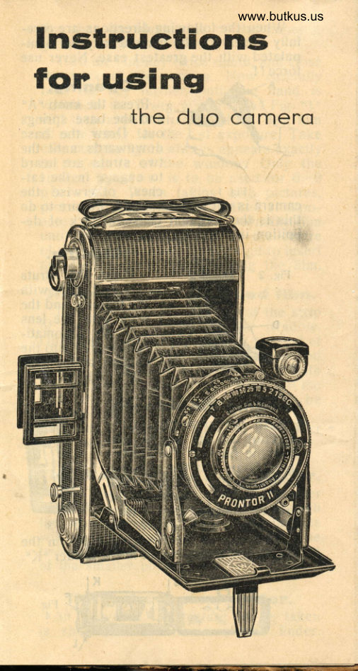
              n Press the knob "A"                    -and                            the base springs
                       out. Draw the base
                     downwards until the
                    two struts are heard
                        to engage in the cat-
               Fig  I       ches, otherwise the
     camera is not perfectly rigid. Failure to do
       this is the frequent cause of lack of de-
       finition in the negatives.
                       Glosing.
                         Press the struts                                     .'E( With                                  ,,,Du and
                            the thumbs, and the
                              front with the lens
                          will be automati-
                                  cally folded into the
                           camcra, as the base
                      uBu is closed.Mike Butkus                                                    DigitallyDN:Date:cn=Mike2022.04.23signedButkus,by18:45:31Mikeo=ButkusButkus-04'00'camera manuals, ou=butkus.org, email=mike@butkus.org, c=US
     Locrding the ccrmercr.'
       Push the knob "F" in the      direction of the arrow, and
      open the back of the camera
                            nickeled     "H'. Draw out the      knob and put in the new spool
     of film at "J". Rernove the
       strip of gummed paper from
                                                     3    the spool, and insert the   Fig
      pointed end of the covering paper in the
       slot of the ernpty spool in the holder "K".


                                                             Fig.
                                                                              A
View original page 2Page 3 · Read text
www.butkus.us
 See that the black side of the paper is
 turned towards the lens.
   Turn the film key twice round, and close
 the back of the camera. Now carefullv
 turn the key further, until the hand  i-s
 visible in the lower window. and Fig. ,,1,,
 will then appear after the d6ts Thd film
 is now ready for the I st exposure. Take
 care that the figure always appears exacily
 in the centre of ttre winOoiv. Onlv thi:lower window is to be used tof6><9 picturcs. When taking 4><6 pictures,
 proceed in the same way for the I st expo-
 sure; for the 2nd, however, turn the film
 until the No. " 1,, appears in the centre
 of the upper window. Dont forget to insert
the 4><6 mask before winding the film.
 Removing the exposed film.
       the key until the end of the strip
of-T-gInfilm is to be seen in the window.
Open the back "H", and keep the end ofthe filrn tight, so that it is closely wound
on the spool. Now fasten the film with
the strip of gummed paper. Draw out the
film key, after which the spool may be
removed easely.
   Putting in the empty spool in the holder .
tor a new film, draw out the film key.
The dinect vision view finder.
  Hold the sight of the back and smaller
part, close to the eye. Looking through
the larger frame with the rectangular Iens
will give the linrits of the picture. The
two rods may be used to show the limits
of the smaller picture.
  The opticol view finden.
 An image of the picture to be takenis shown in the frame of the finder.
View original page 3Page 4 · Read text
Bitte spenden Sie 2,50 Euro, um diese Website über E-Bay zu unterstützen ... www.PayPal.me/butkusView original page 4
Page 5 · Read text
Fig.5 shows the lines for the horizontal and
vertical pictures. When taking horizontal

Verti-                                      I     Hori- - cal                                          zontal
pictu res                                     pictures
                        Fig. 5
pictures, turn the view finder g0 degrees.
The optical view finder for cameras with
the mask is marked with red dotted lines
"N" (Fig. 5) for the smaller pict:rre. These
red lines mark the limits of the horizontal
and vertical pictures of smaller size in the
same manner.
 CAMERA BCDDY RELEASE.
 When opening the camera the small
nickelled knob on the side of the direct
vision view finder automatically springs
out of the body. The release of shutter
is then effected by pressing this knob.
  Hold the camera with both hands: with
some practise instantaneous shots of
longer exposure will be possible.
 When closing the camera press the
knob in and it is locked automatically
View original page 5From the M. Butkus archive. Original publisher and archive notices are retained.
Check the model and edition against your equipment.
PDF verified 2026-10-10.