Film cameras
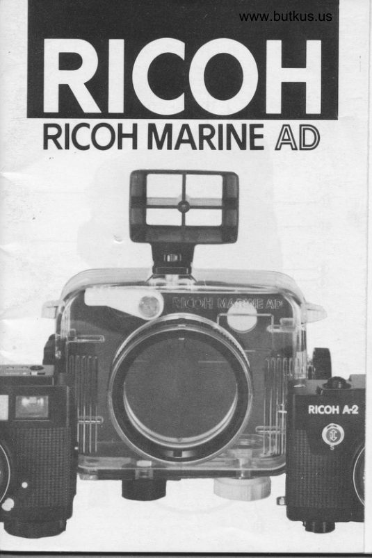
Ricoh Marine AD User manual
User manual for Ricoh Marine AD. 44 pages. Read the original PDF, download or print a copy without registration.
44 pagesOriginal document2.9 MB PDF
Loading your manual…Open PDF directly
Document details
- Brand
- Ricoh
- Model / document
- Ricoh Marine AD
- Document type
- User manual
- Language
- Check the original document
- Pages
- 44
- File size
- 2.9 MB
- Category
- Film cameras
- Document date
- Not specified in catalog
Search available document text
Find a term, then jump to its page in the original PDF. Image-only pages may not be searchable; check the PDF for exact wording and diagrams.
Page 7 · Read text
Digitally signed by Mike Butkus
                                DN: cn=Mike Butkus, o=Butkus
                                camera manuals, ou=butkus.org,Mike Butkus email=mike@butkus.org, c=US
                                      Date: 2022.02.19 18:47:42 -05'00'
View original page 7Page 8 · Read text
www.butkus.us
We know you will be more than satisfied with your
purchase of the new RICOH MARINE AD underwater
and all-weather housing.
The RICOH MARINE AD was designed for use with the
RICOH AD-l and A-2 cameras, and can be used to
depths of 30m. (98 ft.)
Both amateur and profassional photographers will be
delighted with the features  it offers. Besides underwater
photography, the RICOH MARINE AD is ideal for wet and
humid conditions which might otherwise be detrimental
to your camera. Use it for skiing, water sports at the pool
side or beach. or work on the muddy construction  site.
Be sure to read this manual carejully. before you use
your RICOH MARINE AD.

PARTS
  1. Distance Adjustment Ring
  2. Shutter Release Lever
  3. Lock Arm
 4. Lock Lever
  5. Flash-socket
  6. Wind-knob
  7. Wind-knob Connector
  8. Front Glass
  9. Screw-socket for Sports Viewfinder
 10. Strap Eyelet
 1 1. Camera Securing Screw
 12. Airtight Screw
 13. Viewfinder Window
                     -1-
View original page 8Page 9 · Read text
14. Back Cover O-ring Seal Groove
 1 5. Back Cover
 16. Sports Viewfinder (lncluded)
 17. Sports Viewfinder Fixing Screw
18. Silicone Grease (lncluded)
19. Back Cover O-ring Seal (lncluded)
    Focus Ring (lncluded)
MAIN CHARACTERISTICS
  1. Underwater photography to a depth of 3Om. (g8 ft.)
 2. The housing's design allows the film to be advanced
  .  aiproximately 15 frames, by depressing the water-
    proof shutter.
 3. Continuous shots can be taken automatically.
 4. The spring motor of the camera can be wound from
    the outside of the housing for another 15 frames.
 5. Ease of focusing by simply adjusting the Distance
    Adjustment Ring.
 6. The housing floats.
 7. Fishing trips, beach and pool-side gatherings can be
    enjoyed without damaging your camera.

WAR NING
So as not to void the guarantee for the camera and/or the
Marine Housing, please take the following precautions:
 1. Do not use at a depth greater than 3Om. (gg  ft.)
 2. Always check the seal after closing the Back Cover.
    For a water-tight seal, the O-ring must make an even
View original page 9Page 10 · Read text
www.butkus.us
     contact which shows as a continuous black line
    along the Groove. Dirt or scratches will show as
     lighter markings along the seal imprint.
  3. Do not throw it into the water. (Fig. l)
ATTACHING THE STRAP
  1. First pass the end of the strap through the Strap
     Eyelet (10) and loop it back, then slide it into the
    metal fitting as shown. (Fig. 2)
  2' Adjust the strap to the desired rength and secure it
    with the clip.
  * There are four Strap Eyelet so that the housing can
    be carried vertically or horizontally. (Fig. 3)
INSERTING THE CAMERA
  1. Remove the strap from the camera.
 2. Set the Distance Scale Ring on the camera to the @
    symbol. (Fig.     )
 3, Attach the Focus Ring (.|9) to the camera. The
    indentation mark shourd be positioned against the @
    symbol, on the camera distance scale, (Fig. S)
 4. Set the Distance Adjustment Ring (1) of the Marine
    Housing to the @ symbol. (Fig. 6)
 5. To open the Back Cover, pull the Lock Arm (4) up as
   you push the Lock Lever (3) forward. (Fig. 7)
 6. Pull out the Wind-knob (6). (Fig. g)
 7. Place the camera in the Housing and pushthe Wind-
   knob Connector (7) into position against the wind_
   knob of the camera.
View original page 10Page 11 · Read text
contact which shows as a continuous black line
   along the Groove. Dirt or scratches will show as
    lighter markings along the seal imprint"
 3. Do not throw it into the water. (Fig. 1)
ATTACHING THE STRAP
  1. First pass the end of the strap through the Strap
    Eyelet (1O) and loop it back, then slide it into the
    metal fitting as shown. (Fig. 2)
 2. Adjust the strap to the desired length and secure  it
    with the clip.
  * There are four Strap Eyelet so that the housing can
    be carried vertically or horizontally. (Fig. 3)
INSERTING TH E CAMERA
  1. Remove the strap from the camera,
  2. Set the Distance Scale Ring on the camera to the @
    symbol. (Fig 4)
    Attach the Focus Ring (1 9) to the camera. The
     indentation mark should be positioned against the @
    symbol, on the camera distance scale. (Fig. 5)
     set the Distance Adjustment Ring (1) of the Marine
    Housing to the @ symbol. (Fig. 6)
  5. To open the Back Cover, pull the Lock Arm (4) up as
    you push the Lock Lever (3) forward. (Fig. 7)
  6  Pull out the Wind-knob (6). (Fig. 8)
   7.  Place the camera in the Housing and pushthe Wind-
    knob Connector (7) into position against the wind-
    knob of the camera.
View original page 11Page 12 · Read text
www.butkus.us
 2. Do not leave the equipment in direct sunlight as the
    heat will build up inside the Housing and may
   damage the camera.
TAKING PH OTOG RAPHS ON LAN D
Focusing
  1. Estimate the camera-to subject distance by eye, and
    set the required distance. (Fig. 12)
  * When shooting on land, compose the picture
    through the viewfinder on the camera.
    Warning:
   Do not force the mechanism beyond the points
    marked .o (lnfinity) and close-up, as this may result
     in incorrect focusing of the camera.
  * Check that the Protective Front Glass of the housing
     is clean.
TAKING PHOTOGRAPHS UNDERWATER
Attaching The Sports Viewfinder
Use the Sports Viewfinder (15) for underwater
photography.
  1. Attach the viewfinder securely by tightening the
     Fixing Screw (1 6) into the screw socket on the top of
    the Housing. The wider part of the viewfinder should
    be facing forward. (Fig. 13)
Focusing
Using the Sports Viewfinder
  1. Estimate the camera-to-subject distance and set the
    required distance.
View original page 12Page 13 · Read text
* Because the refractive ratio of water is different from
     that of air, photographic subjects underwater will
    appear closer and larger than in reality. However,
    you should set the distance as it appears to you
     underwater. (Fig. 14)
  * At a depth greater than 20 m, the Distance
    Adjustment Ring may become difficult to turn due to
     the water pressure. Please set the focus required for
     taking a photograph before descending to a depth
     greater than 20 m.
REMOVING THE CAMERA FROM
THE HOUSING
  1. Wash the Housing thoroughly in fresh, lukewarm
    water. Wipe dry with a soft cloth. Then remove the '    camera from the Housing. (Simply reverse the
    process for inserting the camera) (Fig. 15)
  2. When it is hard to open the back cover due to low air
     pressure in the housing, loosen the airtight screw by
     turning it counterclockwise. (Fig. 16)
  * Make sure to tighten the airtight screw immediately
     after you have loosen it.  lf you forget to tighten  it,
    there could be leakage when you use the housing
     underwater.


                     -6-
                                                                                                                                                                                                                                                                                                                                                                                                  j
View original page 13Page 14 · Read text
www.butkus.us
MAINTE NA NCE
  1. Do not clean the Housing with alcohol or thinner.
 2. lf the opening or rocking action becomes difficurt
    lubricate the O-ring with the Silicone Grease
    supplied.
 3. lf the Housing has been used for some time or
    exposed to sandy conditions, remove the O_ring and
    wipe the dirt off both the O-ring and the Back Cover
   Groove. Apply a new thin coating of grease to the
    O-ring and re-insert.
 * Clean with a soft lint-free cloth.
 * Do not use sharp objects such as knives. to remove
   the O-ring.
 4. Change the O-ring if  it becomes deformed or
    scratched.
View original page 14Page 15 · Read text
SPECIFICATIONS
Applicable cameras:
   RICOH AD-1, RICOH A-2
Maximum operating depth:
   3Om (98 ft.) underwater (4 atmospheres)
Materials:
    Polycarbonate  plastic, ABS plastic, Glass, Metal
Seal:
     Airtight back cover O-ring
Camera attachment system    :
   By camera's tripod socket
Film advance mechanism:
    Through the camera's winder advance
Focusing:
   By estimating and setting the Distance Adjustment
    Ring
Viewfinders:
   On land -  Using the camera's viewfinder
    Underwater -  Using the sports viewfinder
Opening and locking system:
    Hinges, Lock lever and lock arm
Dimensions:
   143 mm/ 5.63"  (width) x 1 1 6 mm/4.57  "
     (height) x 81 mm/3.1 9" (depth)
Weight:
   4859 fi7.11 ozl
Equipment lncluded:
    Back cover O-ring x 1     Focus ring X 1
    Silrcone grease X 1        Sports viewfinder X 1
                     -8-
View original page 15Page 16 · Read text
www.butkus.us

 Nous vous remercions d'avoir achet6 re boitier RrcoH
 MARINE AD sous-marin et tout-temps. Nous esp6rons
 que vous en serez plus qus satisfait.
 Le RlcoH MARINE AD a 6t6 concu pour 6tre utilis6 avec
 les appareils AD- 1 et A-2, et il est utilisable jusqu,d 30
 mdtres de profondeur.
 A part la photographie sous-marine, RICOH MARINE AD
 est id6al pour surmonter res conditions humides qui pour-
 raient par ailleurs 6tre nuisible d votre appareil. ld6al
 pour le ski, les sports aquatiques, la piscine at la plage ou
quand il doit fournir un effort sp6cial sur un chantier de
 construction boueux par exemple. Avant d'utiliser votre
RICOH MARINE AD, veuillez lire attentivement le pr6_
sent mode d'emploi.

PIECES
  1. Bague de r6glage des distances
 2. D6clencheur
 3. Bras de fermeture
 4. Levier de fermeture
 5. Douille pour flash
 6. Bouton de bobinage
 7. Connecteur de bouton de bobinage
 8. Verre frontal
 9. Douille d vis pour viseur-sports
10. Oeillet pour courroie
1 1. Vis de fixation de l'appareil
12. Vis D'etancheite
View original page 16
Page 18 · Read text
www.butkus.us
 PRECAUTIONS:
   1. Ne pas utiliser d unaprofondeur exc6dant 30 mdtres.
   2. Toujours v6rifier re sceilement. Le joint torique. rd o0
             il forme un scellement, doit toujours laisser une trace
      noire sur la rainure. Bien v6rifier avec soin s,il n,e_
      xiste pas querque imperfection de sceilement. Les
      salet6s ou rayures peuvent 6tre la cause d,une mar_
     que plus claire sur l'empreinte du joint.
  3. Ne pas laisser tomber l.appareil sur le sol ou dans
       l'eau. (Fig. 1)
 POUR ATTACHER LA COURROIE
   1. Passer d'abord re bout de ra courroie par loeiilet de
       la courroie (1O) et la boucler, la glisser dans la boucle
    de m6tal comme montr6. (Fig. 2)
  2) Ajuster la courroie d ra rongueur d6sir6e et la fixer
    avec l'agrafe.
  * Ouatre oueillets pour courroie ont 6t6 pr6vus en
     sorte que I'appareil puisse 6tre suspendu du haut ou
    par tes c6t6s. (Fig. 3)
POUR INSERER L'APPAREIL
  1. Enlever la courroie de l,appareil.
  2. Sur l'appareil, 169ler le repdre @sur la bague des dis_
    tances sur le trait indicateur. (Fig. 4)
  3. Attacher la bague de mise au point (lg) a l,appareil.
-   La rainure d'empracement devra 6tre r6gr6e sur re
     repdre @ de la bague des distances. (Fig. 5)
View original page 18Page 19 · Read text
4. R6gler le repdre @ de la bague des distances (1)du
    boitier sous-marin sur le trait indicateur de l'appareil.
   (Fig.6)
5. Appuyer sur le levier de fermeture (4) vers l'avant et
    tirer le bras de fermeture vers le haut (3), et le dos du
   boitier s'ouvrira. (Fig. 7)
6. Tirer le bouton de bobinage (6). (Fig. 8)
7.  Placer l'appareil dans le boitier en fixant le connec-
   teur du bouton de bobinage (7) au bouton de bobi-
  nage de l'appareil
8. Serrer fermement la vis de fixation de l'appareil au
                                       +   boitier 11 dans le porte-tr6pied de l'appareil. (Fig.
    9)
9. Fermer le dos du boitier (14), le tenir ferm6 tout en                            I
   poussant le bras de fermeture en place. (Fig. 1O)
* Une raideur initiale peut se faire sentir dans les pid-
   ces mobiles, mais elle disparaitra avec I'usage.
* Bien noter que si le bouton de bobinage n'est pas
   16916 correctement le dos du boitier ne sera pas
   ferm6.
*  S'assurer qu'il n'y a pas de salet6s sur le joint torique
  du dos du boitier

                                                                                                                                                                                                                                                                                                                                                                                I * Appliquer l6g6rement de la graisse au silicium tout
  au tour du joint torique.                         *
* Apr6s avoir ferm6 le dos du boitier v6rifier que le
   scellement est en parfait 6tat en observant l'em-
   preinte continue du trait noir.


                   -12-
View original page 19Page 20 · Read text
www.butkus.us
POUR REGLER L'AVANCE
AUTOMATIOUE DU FILM
  1. Tourner le bouton de bobinage (6) dans la direction
    de la fldche jusqu'd ce qu'il s'arr€te. 10 a 1 5 prises
    de vue peuvent 6tre r6alis6es. (Fig. 11)
  * Attention: Ne pas forcer le bobinage.
Veuillez prendre note de ce qui suit
  1. Ne pas ouvrir le boitier dans des conditions d'hunri-
     dit6 6tant donn6 qu'il pourrait s'en suivre une forma-
     tion de vapeur d l'int6rieur du verre frontal du boitier.
 2. Ne pas exposer l'ensemble d la lumi6re solaire di-
     recte 6tant donn6 que des temp6ratures 6lev6es se
    produiront d l'int6rieur du boitier qui pourraient en-
   dommager I'appareil.

POUR PRENDRE DES PHOTOGRAPHIES
SUR TERRE
Mise au point
  1. R69ler la distance requise sur le trait indicateur.  (Fig.
     121
  t  Pour effectuer des prises de vue sur terre, composer
    l'image d travers le viseur de l'appareil.
    Attention:
    Pour la mise au point, ne pas forcer au-deld du
    repdre .. (infinit6) et du plan rapproch6 6tant donn6
    que la mise au point de l'appareil pourrait en 6tre er-
     ron6e.
 *  S'assurer que le verre frontal du boitier est bien pro-
   Pre'                         - 13 -
View original page 20Page 22 · Read text
www.butkus.us
        son boitier. (En inversant simplement le proc6d6 d'ins6ra-
         tion de l'appareil). (Fig. 15)
         2. Lorsqu'il s'avere difficile d'ouvrir le dos a cause d,une
           pression insuffisa mment faible dans le caisson
           etanche desserrez la vis d'etancheite en la faisant
            tourner dans le sens inverse des aiguilles d'une
             montre. (Fig. 16)
         *  Verifiez ensuite que vous avez bien resserre la vis
             d'etancheite apres cette operation. Si vous aviez
            oublie ce detail important, le boitier ne serait plus
           etanche lorsque vous auriez a l'utiliser en plongee.
        * Attention: Ne pas essuyer avec un chiffon rugueux
           pour 6viter les rayures.

       E NTR ETIE N
         1. Ne pas nettoyer le boitier avec un astringent, de l'al-
           cool ou dilvant.
         2. Graisser le joint torique avec de la graisse au sili-
             cium.
    I
!        3. Le joint torique devra €tre toujours propre et bien
            graiss6. Le nettoyer souvent si l'appareil est utilis6
           dans un environnement sableux. pour cela enlever le
              joint torique, le nettoyer en m6me temps que sa rat-
          nure. Appliquer 6galement une couche l6gdre de
            graisse d nouveau.
        *  Utiliser un chiffon doux mais pas duveteux pour le
            nettoyage.
        * Ne pas utiliser d'objet d ar6tes vives tels que des
            couteaux, par exemple, pour enlever le joint torique.
View original page 22Page 24 · Read text
www.butkus.us
         Poids:
         485 gr.
       E16ments inclus:
            Joint torique du dos x 1
            graisse au silicium x 1
          Bague de mise au point x 1
             Viseur-sports x  1

I{


II
View original page 24Page 25 · Read text
Vielen Dank zum Kauf des Unterwasser und Allwetter-
gehduses RICOH MARINE AD. Wir hoffen, daB Sie da-
mit mehr als zufrieden sein werden. Die RICOH MARIN E
AD wurde so konstruiert, daB sie in Verbindung mit den
RICOH-Kameras AD-1 und A-2 bis zu Tiefen von 30
Metern verwendet werden kann.
Neben Unterwasseraufnahmen eignet sich die RICOH                                                        t
MARINE AD vorbildlich  frir nasse und feuchte Aufnah-                    t
mebedingungen, welche sich andernfalls fur lhre Kamera
als gefiihrlich erweisen konnten. ldeal zu verwenden          I*
beim Skilaufen, Wasser-sport, in der Ndhe von Sch-
wimmbecken und am Badestrand. oder unter schwieri-
gen Arbeitsbedingungen auf schmutzigen BauplStzen.
Bevor Sie jedoch lhre RICOH MARINE AD gebrauchen,
lesen Sie bitte diese Bedienungsanleitung  grrindlich und
ganz durch.

BEZEICHNUNG DER EINZELTEILE
  1 . Entfernungseinstellring
 2. Auslosehebel                                   *
 3. Verriegelungsarm                                                                                                                                                                                                                                  Fi
 4. Verriegelungshebel                                                                                                     I
                                                                                                             j 5. Blitzlichtanschluf3
 6. Aufzugsknopf
 7. Verbindungsstrick des Aufzugsknopfes
 8. Vorderlinse
 9. SchraubenanschluB fur Sportsucher
1O. Tragriemenose
1 1. Kamera-Befestigungsschraube
                _18_
View original page 25Page 26 · Read text
I                                  www.butkus.us
        12. Luftdruckschraube
        13. Sucherokular
        14. Dichtungsnut frir O-Ring der Ruckwand
                          'l 5. Rtickwand
             1 6. Sportsucher (Mitgeliefert)
        17. Befestigungsschraube des Sportsuchers
        18. Silikonfett (Mitgeliefert)
 {      19, O-Ring fur RrickwandabdichtunO  (Mitgeliefert)
              Scharfeinstellring  ( M itgeliefert)
 I   HAUPTMERKMALE
           1. Unterwasseraufnahmen bis zu einer Tiefe von 30
             Metern.
         2. Das Gehduse ist so konstruiert, daB der Film tran-
               sportiert werden kann. Durch einfaches Drucken des
            wasserdichten Auslosers konnen ungefdhr 15 Auf-
  t        hahmen gemacht werden.
         3. Fortlaufendes Fotografieren kann automatisch
             durchgefrihrt werden.
 .)      4. Bequemes Scharfeinstellen durch leichtes Drehen
          des Entfernungseinstellr inges.
         5. Das Gehduse schwimmt.
         6. Ohne Angstgefrihle, daB die Kamera zerstort werden
  '            konnte, konnen nun Aufenthalte am Badestrand. am
          Schwimmbecken oder ein Fischfang-Ausflug  genos-
           sen werden.

    WARNUNG
       Die nachfolgenden Punkte unbedingt genau beachten,


        I
View original page 26Page 27 · Read text
um das Eindringen von Wasser zu verhindern. Die nach-
folgenden VorsichtsmaBnahmen mtissen immer einge-
halten werden, andernfalls konnte ein Garantieanspruch
frir die Kamera und das Unterwassergehiiuse  nicht mehr
gewdhrleistet werden.

VORSIC HTSMARNAH M EN:
  1. In einer Tiefe von mehr als 30 Metern darf die Ka-                                                                                  |    mera nicht mehr verwendet werden.
  2. lmmer auf gutex Abdichten achten. Der in der Nut       I
    eingelegte O-Ring sollte mit geschlossener    l
    Ruckwand auf seiner ganzen Abdichtfldche als sch-
     warzer Strich sichtbar sein. Vorsichtig auf eventuelle
     Ungleichheiten der Abdichtung achten. Schmutz
    oder Kratzer konnten durch hellere Schattierungen
     sichtbar werden.
  3. Die Kamera nicht fallen lassen oder ins Wasser wer-
    fen (Fig. 1 )
BEFESTIGEN DES TRAG RIEMENS
  1. Zuerst das Ende des Tragriemens durch die Tragrie-                                    I .  menose (10) fuhren und umbiegen, danach wie ab-
     gebildet in den Metalleinsteller einschieben (Fig. 2).  2. Den Tragriemen auf die gewUnschte Ldnge einstel-   t
     len und mit der Klammer sichern
  * Es sind vier Tragriemenosen angebracht, so daB die
    Kamera entweder von oben oder von der Seite getra-
    gen werden kann. (Fig. 3)
View original page 27Page 28 · Read text
www.butkus.us
    EINSETZEN DER KAMERA
        1. Den Tragriemen von der Kamera abnehmen.
        2. An der Kamera den Markierungspunkt @ am Entfer-
           nungsskalaring mit der Einstellindexlinie ausrichten
           (Fig a).
       3. Den Scharfeinstellring (19) an der Kamera anbrin-
          gen, wobei die Positionsnut mit dem Markierung-
           spunkt @ an der Entfernungsskala der Kamera aus-
I           gerichtet wird (Fig. 5).
       4. Den Markierungspunkt @ am Entfernungseinstellring
          des Unterwassergehiiuses mit der EinstellindexlinieI
         an der Kamera ausrichten. (Fig. 6)
        5. Den Verriegelungshebel  (4) nach vorne drucken und
          den Verriegelungsarm (3) nach oben ziehen, danach
            offnet sich die Ruckwand (Fig. 7).
        6. Den Aufzugsknopf (6) herausziehen (Fig. 8).
        7. Die Kamera in das Gehduse einsetzen, indem das
           Verbindungsstrick des Aufspulknopfes (7) mit dem
           Aufspulknopf der Kamera fixiert wird.
       8. Die am Gehduse angebrachte Kamera- Befesti-
          gungsschraube (11) in den StativanschluB der Ka-
I        mera eindrehen und festziehen (Fig. 9).
       9. Die Ruckwand (14) schlieBen, indem im nieder-
            '    gedrtickten Zustand der Verriegelungsarm (3) inI
           seine Ausgangsstellung gebracht wird (Fig. 1O).
       * Die bewegten Teile konnten anfdnglich etwas sch-
          wergdngig sein, aber diese Erscheinung wird mit zu-
        nehmendem Gebrauch verschwinden.
View original page 28Page 29 · Read text
*  Bitte beachten Sie, daB wenn der Aufspulknopf nicht
            richtig angebracht wird. die Ruckwand nicht ge-
           schlossen werden kann.
       * Besonders darauf achten, dal3 der O-Ring der
          Rrickwand stets schmutzfrei  ist.
       * Den O-Ring leicht mit Silikonfett einschmieren.
       * Nach dem Schlie8en der Rrickwand muB auf tadello-
          ses Abdichten geachtet werden, indem der O-Ring
           auf seiner ganzen Abdichtfkiche als schwarzer Strich
            sichtbar sein mu8.

    EINSTELLUNG DES AUTOMATISCHEN
t{l    FILMTRANSPORTS
        1, Den Aufzugsknopf (6) bis zum Anschlag in pfeilrich-
          tung drehen. Es ist jetzt moglich 10 bis 15 Aufnah-
        men zu machen (Fig. 1 1).
       * Warnung: Nachdem der Mechanismus aufgezogen
         wurde, darf nicht mehr mit Gewalt weitergedreht
          werden.
      Bitte die nachfolgenden Hinweise beachten
         1. Unter heiBen und feuchten Luftverhdltnissen sollte
          das Gehduse nicht geoffnet werden, da dies zum Be-
         schlagen der Vorderlinse auf der Innenseite des
         Gehduses fuhren konnte.
       2. Die Ausrustung nicht direkter Sonnenbestrahlung
           aussetzen, da sich im Inneren des Gehduses Hitze
           anstaut und die Kamera dadurch beschddigt werden
            konnte.
View original page 29From the M. Butkus archive. Original publisher and archive notices are retained.
Check the model and edition against your equipment.
PDF verified 2026-10-10.