Light meters
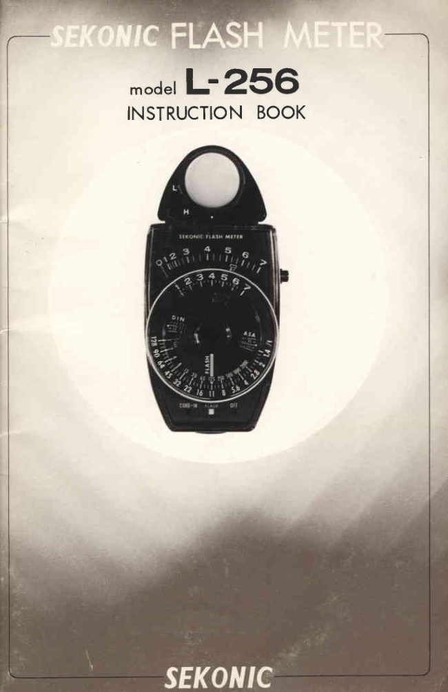
Sekonic TO L-256D User manual
User manual for Sekonic TO L-256D. 28 pages in English. Read the original PDF, download or print a copy without registration.
28 pagesEnglish2.2 MB PDF
Loading your manual…Open PDF directly
Document details
- Brand
- Sekonic
- Model / document
- Sekonic TO L-256D
- Document type
- User manual
- Language
- English
- Pages
- 28
- File size
- 2.2 MB
- Category
- Light meters
- Document date
- Not specified in catalog
Search available document text
Find a term, then jump to its page in the original PDF. Image-only pages may not be searchable; check the PDF for exact wording and diagrams.
Page 3 · Read text
-iI


         Readthis instructionbooklet on
           the Sekonic FlashMeter L-256D
            carefully. With proper applica-
            tion  of  these techniques, you
              will be able to  evaluate the
         improvementin your first roll of
            film.


www.orphancameras.com       '.;rr..,4{r                     ii.j
View original page 3Page 5 · Read text
FACTS ABOUT YOUR
SEKONICL.256 FLASH METER


1 .  The Sekonic F lash Meter is an
    advanced model of the famous
    Sekonic Stud io Meter Series. lt
       is  designed  for  easy     i nstan-
    taneous flash metering.
2 .  The  F lash Meter  is a durable
    met er d esigned fo r years of  re-
      liable service. lt contains superi-
      or  electron ic components and
     circu its f or greater reliability.
3.  The F lash Meter contains a sili-
    con diode  light sensor for  in-
    stantaneous response to   light
     (10 micro-sec.), greater stability
    and extreme accuracy in  light
    measurement.
4.  Th is meter is not on ly designed
      for flash metering, but can also
    be used for  incident  light and
     reflected light metering.
5.  The meter works with  or with-
     out  a sync-cord. Wireless meas-
     urement makes operation very
    easy and you can work without
     the  restrictions of  limited cord
     d istance. Of course, you can use
     a  sync-cord  wherever  you  so
     d esire.
6.  The  meter  pointer  will  hold
     the  light reading for a m in ute
     d uration.   lt  then  wil I  auto-
     matically cancel the reading for
     the next light measurement.
7 .   F or  special app I ications,  th is
     meter works as a slave unit for
     your add itional electronic f lash.


                                      2
                           www.orphancameras.com
View original page 5Page 7 · Read text
NAME OF PARTS


( 1 ) Lumisphere
l2l L Mark
(3) H Mark
l4l White dot mark

(5) Light Scale
(6) Meter pointer
17l Battery check mark
(8) Measurement switch
(e) Dial light scale
( 1 0 ) Ridges for film speed
( 1 1 ) Calculatordial AH mark
n2l Calculatordial AL mark
( 1 3 ) DIN scale
114l ASA scale
( 1 5 ) FLASH INDICATOR
(16) SHUTTER scale(for normal exp. reading)
117l f/number
( 1 8 ) Slide switch marks
( 1 e )Slide switch


         Lumidisc                      Rellected-li ght fi lter


                                      4
                           www.orphancameras.com
View original page 7Page 8 · Read text
Sync-terminal(20)

               Batterychambercover(21)


                 Battery check switch (22)


              Zero adiustmentscrew (23)


                      Tri-pod threading (24)

                  Neck strap ring (25)


Sync-cord
View original page 8Page 10 · Read text
2.  Checkthe Battery                 Move the slide switch to FLASH
                                                 or CORD-lN. Push the battery
                                           check switch dorrun.
Check the battery before you use the
 meter. A  weak  battery  with  low
 voltage will  not  give correct  light
 readi ngs.

 How to check the battery
      (a)  Turn  the  slide switch to
                  t h e F L A S H o r C O R D - I N
          position.
        ( b ) P u s h     t h e    " B A T T E R Y
       CHECK"  switch on  the
        back of the meter in the
          direction of the white ar-
          row.
      (c)  The  meter  needle  will
          point to the battery check
        mark on the light scale. lf
          the  needle  fails to  reach
          the  mark,  the battery  is
        weak and should be  re-
         placed by a new one.

                                              Adjust the pointer to zero by
                                                turning the screw.

3.   Zero setting adjustment
When the slide switch and measure-
ment switch are in the OFF position,
the pointer should be at zero.  lf   it
isn't, turn the zero adjustment screw
on the back until the position is on
zero,
To  Adjust    Turn  gently with  a
screw driver until the pointer comes
to the zero position.
View original page 10Page 12 · Read text
4.   Sync-Cord.
Use the accessory cords  for  wired
measurement.The meter comes with
one 20 foot sync-cord and two polar-
ization alternate cords (in black and
red).


REMARKS
*  The external sleeve of  the flash
   meter sync terminal is the nega-
   tive pole (-)  and the inside re-
   cepter is the positive pole (+).
*    lf  the polarization of the sync-
   cord and the flash unit do not
   match, the flash will not go off
  when you push the measurement
   switch of the meter. (Seepage 12
    for operational i nstruction)
*  Use  the  polarization  alternate     Red cord has       Black cord has
   cords when your flash unit has      (+)  pole on           (-) pole on the
   reversedpolarization to the meter      the central pin,      p t n .
   term inal.
*    lf the flash unit has the positive
   pole  (+) on  the inside receptor
   and negative (-)  on the external
   sleeve, use the  red  alternating
   cord connected with  the 20 foot
   sync-cord.Or   if your flash unit
   has the negativepole on the inside
   receptor and the positive pole on
   the external sleeve,use the black
   alternating cord connected with
   the 20 ft. synccord.
*  When the  polarization of your
   flash unit  is unknown, try both
   alternating cords and use the one
   that works.        tldd
View original page 12Page 14 · Read text
(f)  Transfer the meter reading to
    the calculator dial after you fire
    the f lashunit.
      *   When you  use the  "L"
        range on  the  lumisphere,
        match the green "L"  mark
          of the dial to the read-out
        numbers.
      *   When you  use the
        range on the  lumisphere,
        match the red A"H"  mark                                         Point  the  meter toward  the
          of the dial to the readout                                  camera from  subject position.
        numbers.
(s) Flash indicator opposite the ^       Fire the flash for measurement.
    marks designates the  correct           Transfer the read out number
    f/number to use.                       on the light scale to the calcula-
( h )  Don't be confused by the num-             tor dial and read the number on
    ber 125 which falls at the base          the other side of the dial.
     of the flash indicator. This shut-
     ter speed number is for normal
    exposuremeter readings.
( i )  For best light metering remem-
    ber to place the meter as close
     to  the subject as possible and
     point  the  meter toward  the
    camera. Keep  the  lumisphere
    clean by  washing with  luke
    warm water when  it gets dirty.
View original page 14Page 16 · Read text
Push the measurement switch
                                                       for  f iring flash and simultaneous
                                            reading of the exposure.
(g) To hold the reading automati-
     cally for a  minute, move the
     slide switch from CORD-lN to
    F LASH  while  depressing the
    measuringswitch.
(h) Read the meter using previous
     instructions.


                                          Meter holds the pointer until
                                           you  release the measurement
                                                switch.


                                              fr,,d
                                           While you  push the measure-
                                       ment  switch, move the  slide
                                             switch to FLASH  position to
                                              hofd pointer automaticallv tor 2
                                           minutes.


NOTE:
Don't be concernedif your flash unit
should go off when you connect the
sync-cord to the meter or when you
move the slide switch to CORD-IN
from OFF while the cord is connect-
ed. There is nothing wrong with your
flash unit or the meter.
View original page 16Page 18 · Read text
(d)  Transfer the reading to the cal-
     culator dial. When you use the
     "L"  range, match the green A
     "L" mark of the dial to the read
    out number. When you use the
    "H"  range, match the red "H"
    mark of the dial to the read out
    numbers.
(e)  Flash indicator opposite the ^
    mark  ind icates the  correct  f /
    number to use.
(f)  Don't be confused by the num-    Measure the light at the
    ber 125 which falls at the base     closest  position to  the
     of the flash indicator. This shut-     subject as possible.
     ter speed number is for normal,
    non-flash exposure meter read-
     Ing.                                    Transfer the read out number of
                                              the light scale to the calculator
                                                      dial. Read the f/number on the
                                            opposite side of the dial.
View original page 18Page 19 · Read text
AS A NORMAL EXPOSUREMETER
FOR INCIDENT & REFLECTEDLIGHT

                                 Measuring light as a normal ex-
                                  posure meter

                               Mount the lumispherefor incident
                                                   light reading and the reflected-light
                                                         filter for reflected light reading. Re-
                                 member with  reflected light measur-
                                            ing to set the f ilm sensitivity twice as
                                        high as the film rating ASA.


 Lumis p h e re    f o r      i n c i d e n t      l i g ht
 measurement.
 Reflected-light   filter  for  reflect-
 ed light measurement.


Set ASA rwice as high as film
 ratrng.
                    HOW TO  MEASURE  THE
                          LIGHT
                                              (a)  Set the slide switch to CORD-
                                                   lN. Don't attach the cord.
                                                (b)  Push the measurement switch
                                                     for light reading.The meter will
                                                react instantly.
                            NOTE:
                                          While pressingthe measurementSet the slide sruitch to CORD-tN.                                                switch, the meter pointer don't
                                     move from  the   first  reading
                                        even   if  the light ing condition
                                                  c h a n g e s .
                                                (c)  Read the number the pointer
                                       shows and hold the measuring
                                              swltch until you read the num-
                                            ber or the pointer will return to
                                                zero. (To hold the pointer auto-
                                              matically switch the slide switch
Push the measurement switch                  to FLASH right after metering.
for exposure reading.                     The pointer will hold the read-
                                                ing     approximately a min-                                 16            .for
                           www.orphancameras.comute.l
View original page 19Page 20 · Read text
( d)  Transfer the reading to the cal-
    culator dial. Match  the mark
    according to the lumisphere or
    reflected-light filter mark.
    Match the "L"  mark when the
    sphereor filter is set to "L" and
    match the "H"  mark when the
    sphere or  filter  is set to  "H"          Read out the number pressing
    mark.                                    the measurementswitch.
( e)  Read out the shutter f/number
    combinations at the bottom  of
    the calculatordial.


                                            Transfer the read out number to
                                              the calculator dial.

NOTE:
Don't be confused by the flash indi-
cator arrow. 1 l125th sec represents
one of the shutter speedsyou can use
with the combination of f/numbers.
You have a choice of shutter f/num-
bers combinations from  1 second to
1 I2OOOsec and I l1 .4 to 128.
                                     Read the combination of  the
                                                 shutter speed and f/numbers.


                                    Move the slide switch to FLASH
                                                     to hold the pointer.
View original page 20Page 21 · Read text
I L LUM INAT ION
& CONTRAST MEASUREMENT

                                 You  can measure the illumination
Mount the lumidisc for contrast          contrast between the main light and
measurement.                                    fill-in light to control the illumina-
                                              tion  contrast. (With the use of the
                                     lum id isc)


                   HOW TO MEASURE ILLUMI.
                        NATION CONTRAST
                                             (a)  Mount the LUMIDISC to  the
                                         meter body, following the same
                                         procedure  f or  the Lumisphere
                                                 or the reflected-lightfilter.
                                              (b)  Meter operation with or without
                                              the  sync-cord is the same as
                                             ihcident light measurement.


Take the ratio of the readingat
the high light and shadow.


                           www.orphancameras.com
View original page 21Page 22 · Read text
ILLUMINANCEMEASUREMENT

How  to  measure the  illuminance         Set the slide switch to CORD-lN
( l u x ) w i t h t h e L U M I D I S C . T h e m e t e r            for  illumination measurement
can be used as an illuminancemeter          with lum idisc.
with Lumidisc.

MEASUREMENTPROCEDURE
( a ) M o u n t  t h e L U M I D I S C  t o   t h e
    meter.
(b)  Put the slide switch to CORD-
     lN. Face the meter directly to-
    ward the light source and press
    the measurement switch. (Oo
     not use cord for this measure-
    mentl .
(c) Read out the light scalenumber.
    Then convert into illuminance
     units or  lux  from  the  table
    below:
(d) When using "L"  mark, read the
     figure  directly  off  the  table.
    Then  multiply by  1l'125 and         Face the meter to the light and
    you get the Lux-sec.                   push the measurement switch
(e) When you  set the LUMIDISC            for metering.
     to the "H"  mark multiply the
     resultson the table by 32. Then
     multiply by 11125 and you get
    the Lux-sec.


Meter        1     2     3      4 Scale

 Lux      | , 7 4 0  3,480 6 , 9 6 0   | 3,920


 Meter        5     6     7 Scale

 Lux 21,840 55,680| | 1 , 3 6 0
View original page 22Page 23 · Read text
SPECIAL APPLICATIONS


                                              1.  As a slave unit
 The meter sets off the addition-
 al  f lash unit synchronizing to         This meter works as a slave unit for
 the FLASH unit.                       your additional flash to synchronize
                                                                      it to the main flash unit.


                              How  to apply
                                             (a)  Mount  the lumisphere to  the
                                            meter.
                                             (b)  Set the slide switch to FLASH
                                            o r C O R D - l N .
                                                (c)  Connect the meter and addition-Use the  lumisphere for  s lave
unit  application setting s l i d e                  al f lash unit with synccord.
                                             (d) When you  fire the main flashswitchto FLASH.
                                                   unit, the additional flash unit
                                                   fires simultaneously.


                              ?o
                           www.orphancameras.com
View original page 23Page 24 · Read text
EXAMPLE OF SPECIAL AP.
   PLICATION
     (a)  Connect the meter to the addi-
          tional flash unit with sync-cord.


                                          The meter synchronizesthe ad-,L               fi                                                     ditional flash unit to the main
-                                           F LASH unit.
,*
 Ii
 -i#    (bl Put  the  meter  at  the  subject
-EI        position connecting to the ad-         ditional flash unit. Then you
        can read the exposure of all the
          lights simultaneously. In  this
         case, set  the  slide switch  to
       FLASH.-lft                                                                              thet                                        The  f lash meter measuresall
                                                         light simultaneously,including
*                                                the slaveunit.


                      .":i*.a&E{d#ee;          .lde{a&sr;*,4i&il               ;ee:,.,   x                    "" "*
View original page 24Page 26 · Read text
(1)  store the meter in a dry place.     when  your meter fails to  function
l2l  Keep the lumisphere and lumi-      properly bring  it to a copal Service
    disc clean. When dirty, wash      Station.
    them  with  soapF  in"'  lukewarm    When you return a meter for repair,    water.
(3)  AvoiJ storagewith metals, elec-     pack it with specialpacking materials
     trical parts or chemicals.               to protect it'
Al  Avoid shocking the meter.


,,*;E;**.,,*,t';;i*'ir.                                                                                                             :..., i :,,ddgs6            .-r];].                       "   *
View original page 26Page 28 · Read text
Sole Export Agent:
 COPAL COMPANY LIMITED
  Shimura2- 16-20, ltabashi-ku,Tokyo, Japan
  Telephone:Tokyo965-1 1 1 1, Telex: J24521COPALSUN,
  Cable: COPALSHUTTERTOKYO
 COPAL CORPORATION OF AMERICA
  58-25QueensBlvd., Woodside,New York 11377, U.S.A.
  Telephone: 212/ 672-9 100,
  Telex: 422226 HAGO Ul, 146342 HAGO NYK,
  Cable:HARRYGOCHONEWYORK
 COPAL CORPORATION OF AMERICA,
 LOS ANGELES DIV.,
  2201OSouthWilmingtonAvenue,
  Carson California9OT45, U.S.A.
  Telephone: 21 3/ 83O-4522
  Telex: 688482 COPAL LA CRSN
 COPAL EUROPE GMBH
  Spaldingstr.110, 2000 Hamburg1, West Germany
  Telephone:O4O/280 13 45
  felex: 2163493 COPL D
  Cable: COPALSHUTTERHAMBURG
 COPAL (XOruE KONG) LIMITED
 Room 1119, Tung Ying Bldg., 100 NathanRoad,
  Kowloon,Hong Kong
  Telephone: K-676225, Telex: 84048 COPAL HX
  Cable: COPAL HONGKONG

Manufacturer:
 SEKONIC CO., LTD.
  558, Oizumigakuen-cho,Nerima-ku,Tokyo, Japan
View original page 28
Related documents and language editions
From the M. Butkus archive. Original publisher and archive notices are retained.
Check the model and edition against your equipment.
PDF verified 2026-10-10.