Sewing machines
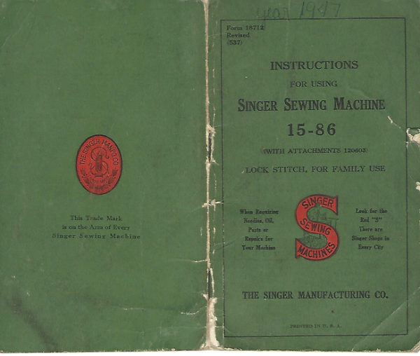
Singer 15-86 — User manual
User manual for Singer 15-86. 24 pages in English. Read the original PDF, download or print a copy without registration.
24 pagesEnglish7.5 MB PDF
Loading your manual…Open PDF directly
Document details
- Brand
- Singer
- Model / document
- Singer 15-86
- Document type
- User manual
- Language
- English
- Pages
- 24
- File size
- 7.5 MB
- Category
- Sewing machines
- Document date
- Not specified in catalog
Search available document text
Find a term, then jump to its page in the original PDF. Image-only pages may not be searchable; check the PDF for exact wording and diagrams.
Page 2 · Read text
18712

 THE IMPORTANCE OF USING          SINGER SEWING MACHINES

   SINGER OIL FOR YOUR                             15-86
     SEWING MACHINE

                                                             (WITH ATTACHMENTS 120603)

   "The Best is the Cheapest                                              OSCILLATING SHUTTLE, FOR FAMILY USE


 KNOWINGexperiencefromthe greatmanyimportanceyears

   of using GOOD OIL, we put

   up an extra quality machine oil.

    in cans, especially prepared for                                                ISINGER

    sewing machines.


Genuine Singer Needles should be used
          in Singer Machines.
  These Needles and their Containers
         are marked with the
 Company's Trade Mark "SIMANCO." 1


     Needles in Containers marked
       "For Singer Machines'
      are not Singer made needles.   2                   PARTS OF THE MacHInE StanD

                                                   A. BELT GUIDE                     D. TREADLE
    Copyright, U.S. A., 1915, 1920, 1923, 1924, 1928,
       1929, 1931, 1932, 1933, 1935 and 1937                B. BanD WHEEL                      E. BELT SHIFTER
          by The Singer Manufacturing Co.                    C. BanD WHEEL CraNk                                                                       F. Leg
          All Rights Reserved for all Countries                                   G. DRESS GUARD
View original page 2Page 3 · Read text
To all whom it may concern:
                                                            To Operate the Machine
    The placing or renewal of the name
  "Singer" (Reg. U. S. Pat. Off.) or any of               Raise the presser foot (B) by means of the presser                                                        bar lifter (C) to prevent injury to the foot (B) and
   the trade marks of The Singer Manufac-          feed (A).
   turing Company on any machine that has
   been repaired, rebuilt, reconditioned, or

   altered in any way whatsoever outside a

   Singer factory or an authorized Singer
   agency is forbidden.                                      SINGER

                                       C
            NOTE
   Although this book contains general instructions

 covering the use of the machine and its attachments,

 if you are further interested, you can obtain a copy

of our book "Short Cuts to Home Sewing," which
 gives more detailed instructions.
                                                                                      FIG. 2. FRONT VIEW OF THE MAcHIND
   A small charge is made for this book as well as
 for three other books which comprise the Singer
 Sewing Library and are a valuable aid in the home.                                                                            It is necessary to undeistand the stop motion
   The additional books are: "How to Make Dresses."          (E) by which the balance wheel (D) can be released
"How to Make Children's Clothes" and "How to       when required, thus enabling the operator to become
 Make Draperies, Slip Covers, etc."                           proficient in the use of the treadle, and permitting
  You are also invited to take full advantage of          the winding of bobbins without running the stitching
                                               mechanism. It also allows the operator to wind Singer Service by calling at any of our shops for
                                                      bobbins without removing partially sewn work andpersonal help with your sewing problems. You will
                                                        without unthreading the machine. receive courteous and prompt attention and there
 is no obligation.
View original page 3Page 4 · Read text
4                               5
   To release the balance wheel (D, Fig. 2), turn the       Do not try to help the machine by pulling the
 stop motion screw (E, Fig. 2) over toward you.          fabric lest you bend the needle. The machine feeds
 It will be necessary to hold the balance wheel while        the work without assistance.
 loosening the stop motion serew.                      The slide over the bobbin case should be kept
                                                          closed when the machine is in operation.
   After releasing the balance wheel, place your feet

 upon the treadle and with the right hand turn the
 balance wheel over toward you. This will start               To Remove the Bobbin the band wheel, treadle and pitman, the sewing
mechanism having been disconnected.                   Turn the balance wheel over toward you until
  Continue the motion thus begun by an alternate        the thread take-up lever (5, Fig. 10) is raised to
 pressure of heel and toe, until a regular and easy
 movement is acquired, and the balance wheel kept

 in continuous rotation by use of the feet alone.
  When you are thoroughly familiar with the treadle
 movement, and can restart the machine without
 turning the balance wheel in the wrong direction,
 tighten the stop motion screw to connect the balance
 wheel with the stitching mechanism.
   Place a piece of cloth under the presser foot, let
 the foot down upon it, and operate the machine in
 this way without being threaded, until you have
 become accustomed to guiding the material.                E10382

   To Ensure Perfect Action of the Machine                                                                                               FIg. 3. REMOVINg THE BOBBIN Case
  The balance wheel must always turn over toward
 the operator.
  Do not run the machine with the presser foot           its highest position. Draw to the left the slide
 resting on the feed without cloth under the presser        in the bed of the machine.Reach down with
foot.                                                   the thumb and forefinger of the left hand, open                                                        the bobbin case latch (A, Fig. 3) and lift out the
  Do not run the machine when both bobbin case        bobbin case. While the latch remains open, the
 and needle are threaded unless there is material       bobbin is retained in the bobbin case. Release
 under the presser foot.                                  the latch, turn the open end of the bobbin case                                              downward and the bobbin will drop out.
View original page 4Page 5 · Read text
6                                     7
             To Wind the Bobbin                     balance wheel hub, and the latch (B, Fig. 5) will
                                                   drop down and hold it. Then operate the treadle
    Release the balance wheel (D, Fig. 2) by turning          the same as for sewing.
  the stop motion screw (E, Fig. 2) over toward you.
  It is necessary to hold the balance wheel (D) while
  loosening the stop motion screw.


   A

               SINGER


                                                                                                                 5/2232


                                                                            FIg. 5. WINDING THE BOBBIN
      FIG. 4. MACHINE THREADED FOR WINDING THE BOBBIN

                                                The end of the thread must be held by the hand
  Place the bobbin on the bobbin winder spindle                                                              until a few coils are wound and should then be
 (A, Fig. 5) and push it up closely against the        broken off. When sufficient thread has been wound
 shoulder, having the small pin in the spindle enter                                                   upon the bobbin, the bobbin winder is automatically
 the slot in the side of the bobbin. Put the spool of                                                              released from the balance wheel.
 thread on the spool pin (1, Fig. 4). Pass the thread
 into the thread guide (2, Fig. 4) at the top of the              If the pressure of the rubber ring (D, Fig. 5)
face plate, then up into the lower eyelet (3, Fig. 5)           against the hub of the balance wheel is insufficient
 of the bobbin winder thread guide, into the notch           for winding the bobbin, loosen the adjusting serew
 (4, Fig. 5) and pass the thread through the slot in         (C, Fig. 5) and press the bobbin winder lightly
the left side of the bobbin from the inside. Press           until the rubber ring is in contact with the hub of
 the bobbin winder pulley (D, Fig. 5) down on the           the balance wheel; then tighten the screw.
View original page 5Page 6 · Read text
8                                                                 9
         To Thread the Bobbin Case
                                                  To Replace the Bobbin Case
                              Hold the bobbin
                              between the thumb          After threading, take the bobbin case by the
                              and forefinger of          lateh, holding it between the thumb and forefinger
                                  the right hand, with
                             the thread on top
                            drawing from left to
               210385           right (see Fig. 6).


              Fig. 6


  With the left hand hold

 the bobbin case as shown in
 Fig. 6, the slot in the edge                                                          •B
being at the top, and place
 the bobbin into the bobbin                          C case.
                                                                             E10379


                                                                      FIG. 9. BOBBIN CASE THREaDED anD REPLACED

                                               E10384
                                     FIg. 7

                      Then pull the thread         of the left hand. Place the bobbin case on the
                             into the slot in the edge          centre stud (B, Fig. 9) of the shuttle body with the
                          of the bobbin case (see          position finger (A, Fig. 9) opposite the notch at the
                            Fig. 7) and down under         top of the shuttle race. Release the latch and press                                                       the bobbin case back until the latch catches the
                           the tension spring into       groove near the end of the stud. Allow about three
     210386              the slot at the end of                                                       inches of thread to hang free from the bobbin case                          the tension spring (see
          Fig. 8          Fig. 8).                         and close the slide in the bed of the machine.
View original page 6Page 7 · Read text
10                                            11


              To Set the Needle                                          5


   Turn the balance wheel over toward you until the

 needle bar moves up to its highest point, loosen
 the thumb screw (A, Fig. 10) in the needle clamp
 and put the needle up into the clamp as far as it
 will go, with its flat side toward the right, then
 tighten the thumb screw.


            Upper Threading

          (SEE FIG. 10 ON THE FOLLOWINg PAGE)

   Turn the balance wheel over toward you until
 the thread take-up lever (5) is raised to its highest
 point. Place the spool of thread on the spool pin
at the top of the machine and pass the thread to the left through the thread guide (1) at the rear
 of the face plate, down, under and from back to
front between the tension dises (2), up back of the
 tension thread guard (3), down into the loop of the
 take-upspring (4), up and from back to front through
 the hole in the end of the thread take-up lever (5),
 down into the eyelet (6) on the face plate, into the
 lower wire guide (7), then from left to right
 through the eye of the needle (8).
  Draw about two inches of thread through the eye
 of the needle with which to commence sewing.                       E17250


                                                                              FIg. 10. UPPER ThrEaDINg
View original page 7Page 8 · Read text
12                                        13

            To Prepare for Sewing
                                                          To Remove the Work
   With the left hand hold the end of the thread,
leaving it slack from the hand to the needle. Turn            Stop the machine with the thread take-up lever
                                                                (5, Fig. 10) at its highest point, raise the presser
                                                           foot and draw the fabric back and to the left, pass
                                                           the threads over the thread cutter (A, Fig. 11) and
                                                               pull down lightly to sever them. Leave the ends of
                                                            the threads under the presser foot.


                                                             To Turn a Corner

                                                         Stop the machine when the needle is commencing
                                                                           its upward stroke. Raise the presser foot and turn
                                                         the work as desired, using the needle as a pivot,
                                                               then lower the presser foot.

                                         1302
                                            To Regulate the Pressure on the Material
        FIG. 11. DRAWINg UP THE BOBBIN TErEaD

                                                                 For ordinary family sewing, it is seldom necessary
                                                            to change the pressure on the material. If sewing the balance wheel over toward you until the needle
                                                               fine silk or flimsy material, lighten the pressure by moves down and up again to its highest point, thus
                                                         turning the thumb screw (A, Fig. 4) on the top ofcatching the bobbin thread. Draw up the needle                                                            the machine over to the left so that it screws up. To thread and the bobbin thread will come up with it
                                                            increase the pressure, turn this thumb screw over to through the hole in the throat plate, as shown in                                                     the right so that it screws down. The pressure Fig. 11. Lay both threads back under the presser
foot.                                                   should be only heavy enough to prevent the material                                                   from rising with the needle and to enable the feed to
          To Commence Sewing                move the work along evenly. The heavier the ma-
                                                               terial, the heavier the pressure; the lighter the   Place the material beneath the presser foot,                                                              material, the lighter the pressure. lower the presser foot and commence to sew, turn-
 ing the balance wheel over toward you.
View original page 8Page 9 · Read text
14                                        15

       To Regulate the Length of Stitch                            Tensions
   The machine can be adiusted to make from 6 to          threadsFor ordinaryshould bestitching,locked inthetheneedlecentre ofandthebobbinthick- 30 stitches to the inch as indicated by the numerals                                                        ness of the material, thus:
 on the stitch indicator plate (C, Fig. 114).
  The number of stitches to the inch that the ma-
 chine is set to make is indicated by the number which
 is in line with the upper edge of the stitch indicator                          FIG. 12. PERrEcT StITCH
(B, Fig. 11a).                                                     If the tension on the needle thread is too tight, or
                                                             if that on the bobbin thread is too loose, the needle
                                                        thread will lie straight along the upper surface of
                To change the length of stitch,         the material, thus:
                   loosen the thumb screw (A, Fig.
                   11a) and move it up or down un-                                                          Ellis
                           til the upper edge of the stitch                   FIG. 13. TIGHT NEEDLE ThrEaD TeNsIoN
                    indicator (B) is in line with the             If the tension on the bobbin thread is too tight or
                 bottom of the number of the de-          if that on the needle thread is too loose, the bobbin
                      sired length of stitch, then tighten         thread will lie straight along the under side of the
                                                         material, thus:                thumb screw (A).
 E12238    A

     Fig. 11a                                                            FIG. 14. Loose NEEDLE ThrEaD TENsIon
                  Basting
                                                             To Regulate the Tensions
   The longest stitch made by the machine, No. 6           The tension on the needle thread should only be
 on the stitch indicator plate, is found satisfactory for        regulated when the presser foot is down. Having
 basting, after loosening the tension on the needle        lowered the presser foot, turn the small thumb nut
thread so that the stitches may be easily pulled       (B, Fig. 4 at the front of the tension discs over
from the material.                                    toward you to increase the tension. To decrease the
  Machine basting is firmer and more even than         tension, turn the thumb nut over from you.
 that done by hand in addition to being much quicker.        theThescrewtension(A, onFig.the7)bobbinin thethreadbobbinis caseregulatedtensionby
                                                              spring. To increase the tension, turn the screw over
        To Sew Flannel or Bias Seams                to the right. To decrease the tension, turn the
                                                                  screw over to the left.
   Use a short stitch and as light a tension as possible
 on the needle thread so as to leave the thread loose         When the tension on the bobbin thread has been
 enough in the seam to allow the goods to stretch        changeonce properlyit, as a correctadjustedstitchit iscanseldomusuallynecessarybe obtainedto
if necessary.                                      by varying the tension on the needle thread.
View original page 9Page 10 · Read text
16                                    17
          To Oil the Machine                  On the back of the arm is a round plate or cover,
   To ensure easy running, the machine requires oil-         fastened by a thumb screw; loosen the serew, turn
                                                      the plate upward and fasten by tightening theing and if used continuously, it should be oiled each
                                                      screw; turn the balance wheel slowly and oil the
                                                           moving parts inside, then turn the cover down and
                                                           fasten it as before.
                                         To reach the parts underneath the bed, the
              SINGER                          belt must be thrown off the band wheel on the
                                            machine stand. For this purpose a belt shifter


   FIG. 15. OILING POINTS AT THE FRONT OF THE MACHINE

 day. With moderate use an occasional oiling is
 sufficient. Oil should be applied at each of the                 FIG. 16. OILING POINTS IN BASE OF MAcHINE
 places shown by arrows in Figs. 9, 15 and 16. One
 drop of oil at each point is sufficient. Oil holes are          (E, Fig. 1) is placed on the front of the band wheel.
provided in the machine for bearings which cannot         By pressing the belt shifter lever to the left and
be directly reached.                                        working the treadle meanwhile, the belt is released
  Draw to the left the slide in the bed of the ma-         and the head can then be turned back on its hinges.
 chine and apply a few drops of oil to the shuttle race         The places to be oiled are indicated in Fig. 16,
 (C, Fig. 9). The slide should then be closed.             by arrows pointing to the oil holes and bearings.
   Loosen the screw (A, Fig. 15) near the upper end        To oil the stand, put a drop of oil on the centres
 of the face plate, raise the plate and slip it off over      on which the band wheel and treadle work, and
 the head of the screw; put one drop of oil into each        both ends of the pitman rod which connects the
 of the oil holes and joints.                                  treadle with the band wheel.
View original page 10Page 11 · Read text
18                                       19

               HINTS

   Belt of Foot Power Stand. See that the belt
 is not too tight. It should always be tight enough      INSTRUCTIONS FOR USING THE
not to slip. If too loose. remove the hook at one
end. shorten the belt and reioin.                    ATTACHMENTS
  Machine Working Heavily. If the machine
 runs hard after standing idle for some time, use a
 little kerosene in the oiling places, run the machine
 rapidly, then wipe clean and oil.                                The Foot Hemmer

  To Avoid Breaking Needles. See that the                             The Foot Hemmer (Fig. 17)
 presser foot or attachments are securely fastened by
                                                                               is attached to the machine in
 the thumb           screw.                  Do                     not sew                             heavy                                   seams                                         or                                            very                             place of the presser foot. Raise thick       goods             with too                      fine                           a needle.                                     A                                       large                                             needle
 and thread to correspond should be used on heavy                              the needle to its highest point,
 work (see inside cover page at back of book).                                 loosen the thumb screw which
   See that the needle is not bent and avoid pulling                         clamps the presser foot to the
 the material when stitching.                                              presser bar and remove the
                                                                            presser foot. Attach the Foot
   Breaking of Needle Thread. If the needle
 thread breaks it may be caused by:                                      Hemmer to the bar, taking
     Improper threading.                                                   coras care to tighten the screw firmly
    Tension being too tight.                             FIg.17. THE FooT so that the Hemmer will not
      The thread being too coarse for size of needle.            HEmmer       become loose when the machine
     The needle being bent, having a blunt point,                            is running. Turn the balance
         or being set incorrectly.                            wheel slowly to make sure that the needle goes
  Breaking of Bobbin Thread. If the bobbin        through the centre of the needle hole and that the
 thread breaks it may be caused by:                          lower thread is properly pulled up.
     Improper threading of bobbin case.
      Tension being too tight.                               How to Start the Hem at the Very Edge
   Skipping of Stitches. The needle may not be
 accuratelv set into the needle bar or the needle may           How to start the hem at the very edge of the
be blunt or bent.The needle may be too small for         material is of great importance in learning to use the
 the thread in use.
                                                           Hemmer. If the hem is not started at the edge and
   Free Instruction for using the machine is gladly         the material is pulled bias a perfect hem cannot
 given at any Singer Shop.                             be made.
View original page 11Page 12 · Read text
20                                                      21
   There are several ways of starting the hem at the         Making a Hem with the Foot Hemmer
 edge, but the most practical one is as follows:
                                                            The same width of material must be kept in the
                                                       Hemmer at all times. After placing the correct


                                                         0393

                                                                 FIG. 19. MAkING A HeM WITH THE FOOT HEMMER

                                                     width of material in the Hemmer hold it in a
                                210380             straight line and you will find it quite easy to make
                                                     a perfect hem. See Fig. 19.
           FIG. 18. STARTINg a HEM AT THE EDGE               Making a Hemmed Seam with the Foot Hemmer
                                                        The hemmed seam is very practical to use on
   1. Fold over about ⅛" of the edge of the material         underwear, or in fact on any garment where a                                                                    straight seam is used and where a small double seam
 at the starting point for a distance of about one inch.        would be suitable.
   2. Place the material in the Hemmer at an angle

 leading to the right at a point just beyond the fold.

  3. Draw the material toward you through the
 Hemmer, as shown in Fig. 18, at the same time
 making the second fold at the very edge. Continue

 to draw the material through the Hemmer until the

 edge is just under the needle. Place the upper and

lower threads together under the Hemmer foot and

assist in starting of the hem by slightly pulling the
threads from the back as the machine is run.                                             E10399

                                                                       FIG. 20. MAKING A HEMMED SEAM
View original page 12Page 13 · Read text
22                                    23
  When using this seam, the garment must first be          bringing it up through the slot at the right of the
 fitted and the edge of the material trimmed, allowing         Hemmer. See Fig. 21. Lower the bar, turn the
 for about one-eighth inch seam. The two edges are         balance wheel and catch the edge of the lace with
placed together and inserted in the Hemmer in the         the needle. Guide the hem with the right hand and
 same manner as a single hem. If the material is          the lace with the left. Care should be taken not to
bulky, the edge of the upper piece of material mav         stretch the lace as it is being fed into the Hemmer.
 be placed about one-eighth inch in from the edge of            It is not practical to sew gathered lace on with
the lower piece. See Fig. 20.                              the Foot Hemmer, as the fulled lace catches in the
  The free edge of a hemmed seam may be stitched         Hemmer slot.
flat to the garment if desired. First open the work
 out flat, then place the hem in the scroll of the       A very attractive way of applying lace so that the                                                                stitching of the hem is not visible is to start the hem Hemmer, which acts as a guide, holding the edge
 of the hem in position while it is being stitched.           in the regular way, slipping the lace in from the Left                                                        as you would the second piece of material when
    If the seam is stitched flat to the garment one row        making a hemmed seam.
 of stitching is visible on the right side.
  The hemmed seam may be used on muslin, lawn,         ADJUSTABLE HEMMER--Hemmingpercale, organdie or other fine materials where a
 narrow seam is desirable.                                      Remove the presser foot and attach the adjustable
 Hemming and Sewing on Lace in One Operation         hemmer in its place, as shown in Fig. 22. This
   Start the hem in the regular way and with the
 needle holding the hem in position, raise the presser


                                                                                    ABOA

                                        E5112                                              FIg. 22
             PIg. 21. HemmIng AND SeWING On Lack
                                                               hemmer will turn hems from 16 inch to 18 inch wide.
 bar sufficiently to allow the edge of the lace to be         The adjustment is made by loosening the thumb
 slipped in under the Foot Hemmer, at the same time         screw on the hemmer and moving the scale to the
View original page 13Page 14 · Read text
24                                     25

right or left until the hem turned is of the desired             Attaching the Binder to the Machine
 width. Place the cloth under the hemmer and draw             Raise the needle to its highest point and remove
 the edge toward the left under the scale, as shown          the presser foot from the machine by loosening the
 in Fig. 22. Draw the edge of the cloth back and

 forth until the hem is formed, stopping with the end
 under the needle. Lower the presser bar and com-

 mence to sew, being careful to so guide cloth as to

 keep hemmer full.
                                                                                                                        AdjustingScrew
  ADJUSTABLE HEMMER-Wide Hemming
                                                                                                               Outside.
   To make a hem more than 18 inch wide, loosen                                               Slot of
                                                                                                                         Scroll
 the thumb screw in the hemmer and move the scale
                                                                                                       Binder
                                                                        Aprón            Scroll
                                                                              Centre Slot 7   E9761
                                                                                          Fig. 24

                                                          thumb screw which holds it in place. Compare the

                                                              foot of the Binder and the presser foot and you will
               ore                      see that they are attached to the machine in the
                                                            same manner. Attach the Binder to the presser bar.
                                                   Turn the balance wheel slowly
                                                        toward you to make sure that the

                                                          Binder is properly attached to the
                                      E8433              bar and that the needle goes through
                                                               the centre of the needle hole.

                         FIG. 23
                                                         Inserting the Binding in
                                                        the Binder
 to the right as far as it will go, then swing it toward
 you as shown in Fig. 23 and tighten the thumb           Cut the binding to a long point
screw. Fold and crease down a her of the desired         to left, as shown. Insert the pointed
 width; pass the fold under the extension at the right        end in the binder scroll (Fig. 26)      FIg. 25
 of the hemmer, and the edge into the folder as         until the pointed end comes through   CUTTING POINT
 shown in Fig. 23, and proceed to stitch the hem.            the lower end of the scroll.              ON BINDINg
View original page 14Page 15 · Read text
26                                     27
  Pull the binding through under the presser foot             The Adjustment and Operation of
before starting to sew. Note that as the binding                        the Binder
 passes through the scroll of the Binder the edges                                                  The edge to be bound should be held well within are turned in.
                                                      the centre slot of the scroll (A, Fig. 28). If the


                                               B
                                E10387

            FIg. 26. INSERTINg BINDINg IN BINDER
 Binding May be Purchased Cut and Folded                         A     E LOCOS
            for Use with the Binder
                                                                                      FIG. 28. ADJUSTINg THE BINDER
  Folded bias binding
may be purchased for                                 material is allowed to slip away from the scroll
use with the Binder.                           when near the needle, the edge will not be caught
                                                               in the binding. With a little practice it is quite easy
and colors. Folded                                       to hold the edge in the scroll.
 bindings for use with                                      Various materials and conditions require different
the Binder must meas-    FIG. 27. INSERT FOLDED            adjustments of the Binder to bring the stitching
                                        IN                                           OUT- ure ⅑" in width. The        BINDINg
                                    SIDE                                         SLOTNo. 5 width in stand-                                      close to the edge. A wider adjustment of the Binder
 ard brands usually measures ½", but it is always         is required when binding curves than is necessary
 well to be sure of this before purchasing.                   when binding a straight edge.
  Folded binding is inserted in the outside slot of the            To adjust the Binder for stitching, loosen screw (B,
 Binder, as shown in Fig. 27. The Binder is adjusted          Fig. 28) and move scroll to the right for a narrower
 and operated in the same manner as when using          adjustment and to the left for a wider adjustment.
unfolded binding. One-half inch braid or ribbon may        Care should be taken to see that the screw is well
 be used in the same manner.                            tightened after making an adjustment. To become  A binding inserted in the outside slot of the Binder
 will be turned only once. It is therefore necessary         perfectly familiar with the adjustment of the Binder,
 to have finished edges when using binding in this slot.          practice is necessary.
View original page 15Page 16 · Read text
28                                    29
          Binding Outside Curves                    of the binder and to the left, allowing unfinished
                                                        edges to swing naturally into the scroll of the binder.
   Practice is required to bind a curved edge properly.
 The edge to be bound must be allowed to pass freely         Never pull the binding as it feeds through the
                                                            Binder, as bias material is very easily stretched and
                                                                will be too narrow when it reaches the needle. When

                                                                this occurs the edges will not be turned.

                                                            When binding a curved edge (see Fig. 29), turn
                                                           the material only as fast as the machine sews. It is
                                                           not possible to hold the material in the entire length
                                                             of the scroll when binding a small curve.

                                         Do not push the material in too fast, as the edge
                                                              will then become puckered, and do not stretch the
                                           E70389
                                                             material or the curve will not be the proper shape
          FIG. 29. BINDINg an OUTSIDE CURVE              when finished. If the stitching does not catch the
                                                   edge of the binding the scroll should be adjusted a
                                                                             trifle to the left.
through the scroll and should not be crowded against
 the wall of it. Guiding should be from the back
                                                                 Binding Inside Curves


                                                                It will be necessary to practice binding an inside

                                                             curve on various kinds of material, as this curve is

                                                            found on nearly all garments which may be finished
                                                      with a bound edge.

                                         When binding an inside curve with the Binder,
                                                           straighten out the edge as it is being fed into the
                                                           attachment. When doing this, care should be taken

                                                                not to stretch the edge of the material.
                   E5074                E 5088
                                                                       If the material is soft, like batiste or crepe de chine,
  FIg. 30. SAMPLE OF OUT-          FIG. 31. SAmPlE oF            add a row of machine stitching close to the edge of
        SIDE CURVE                INSIDE CURVE              the curve before binding.
View original page 16Page 17 · Read text
30                                        31

       Applying a French Fold to a Curve                 The Parts of the Tucker and Their Uses

                                                            Select the Tucker from the box of attachments,
   A French fold is applied by placing the material
                                                               compare it with Fig. 33 and note the names and uses
 under the attachment and stitching the binding in
                                                                  of the various parts, as follows:

                                                                                                    MARRING      TUCK GUIDE
                                                                          CLEVER         ADJUSTING SCREW


                                                             TUCK
                                                               GUIDE

                                                                  TUCK SCALE
                                                              AND
                                                      SMOOTHER                                   SPACE SCALE
                                                       BLADES                                       ADJUSTING SCREW

                                     E70395           SPACE
                                                              SCALE
                                                                     GROOVED,       * SPUR
                                                           BLADE          BLADE                                    C 5310
             FIG. 32. APPLTINg FRENCH FOLDS
                                                                    FIG. 33. THE TUCKER anD Its WorKIng PARTS

                                                         The Tuck Guide, which is adjustable and may be
 position as shown in Fig. 32. A line made by basting
                                                                    set for any desired width of tuck.
 or with chalk or pencil may be used as a guide in
                                                            The Tuck Scale, containing figures which indicate
 applying rows where wanted.
                                                                 different widths of tucks. The tuck scale also
                                                                   acts as a smoother blade, keeping the tucks of
  DAINTY WAYS TO USE THE TUCKER
                                                     The uniformTuck Guidewidth.Adjusting Screw, by means of
                                                                which the tuck guide may be set at any point
   Tucking is the natural trimming for fine materials                on the tuck scale.
such as lawn, organdie, batiste, etc., and may be          The Space Scale, containing figures on the upper
 made without basting in any width from a fine pin              blade which indicate the width of the space be-
 tuck to one inch wide when using the Singer Tucker.             tween tucks. The middle or grooved blade
 The Tucker gauges the width of the tuck and while               contains a groove into which the material is
one tuck is being stitched the mark for the next               pressed by the spur at the end of the lower or
tuck is being made.                                          spur blade, thus marking the goods for the
   It is so simple to make tucks in this way that it is               folding of the next tuck.
 a joy to plan garments with this fascinating trimming.          The Space Scale Adjusting Screw, by means of
Then, too, such trimmings may be made without            which the space scale may be set at any desired
extra cost. The fashion magazines always give                 point.
 numerous suggestions for tucking various garments.         The Marking Lever, which presses on the grooved
The following pages will explain the adjusting and                blade, marking the material as it passes between
 operating of this time-saving attachment.                         the grooved and spur blades.
View original page 17Page 18 · Read text
32                                    33
         Where to Oil the Tucker                                              To adjust the width of space between the tucks
   The only place on the Tucker that requires oiling        loosen the space scale adjusting screw and move the
 is the stud on which the marking lever works. One        space scale until the desired figure is directly in a line
drop of oil occasionally is sufficient at the point       with the centre of the needle hole. You will find indicated by the arrow in Fig. 35. Careless oiling
 will result in oily blades and soiled material. When        a line in front and back of the needle hole to indicate
 the marking lever does not move up and down freely,       the centre.
 it requires oiling. If neglected, it may become so
 dry that it will stay down and cause a drag on the           Before starting to sew, tighten the screw firmly
 material instead of lifting freely as the mark is made.         to prevent the scale shifting when the Tucker is
                                                          in operation.
     To Attach the Tucker to the Machine                The figures on the tuck scale indicate the width of

  Raise the needle bar to the highest point, remove         tuck in eighths of an inch, the marks between figures
 the presser foot from the machine and attach the         are sixteenths. The marks on the space scale are
 Tucker in its place. Care should be taken to see that        double the width of those on the tuck scale, so that the     Tucker            is               securely                        fastened                                 to                                    the                                        presser
                                                bar      when both scales are set at the same figure, blind and     that the            needle                  goes                       through                                 the                                     centre                                           of the
needle hole. Note the position of the marking lever,        tucks without spaces between them are made.
 making        sure             that it                     is in                           the                               lower                                     position                                              and
                                                  that         To make space between tucks, first set the tuck the     needle            clamp                  works                        on                           it                              as the                                     machine                                             sews.
                                                             seale, then move the space scale to the same number
    How to Adjust the Scales on the Tucker             and as much farther to the left as you wish to have
  The width of the tucks and the space between         space. Each number on the space scale represents
 them is determined by the adjustment of the scales.        one-quarter of an inch and each mark between
 Adjustment for width of tuck is made by loosening         numbers one-eighth of an inch.
 the tuck guide adjusting screw, which allows you
 to move the tuck guide to the desired figure on the            Use the table below to assist you in setting the
 tuck scale. The tuck guide should be set just over        Tucker.
 the figure you wish to use. The adjusting screw                            TUCK       SPACE
 should always be well tightened                                                         GUIDE      SCALE
                                                       ⅛" tucks with ⅛"no space     1        11½
                                                    nO
                                    ¼"                             ¼"
                               ½"         nO½"                                          E 40054                     no                                  22448                       3468
                                                          Note Fig. 34, showing Tucker set at a pin tuck
       FIG. 34. TUckeR SeT AT PIN TUCk AnD 2 SPACE               and 2 for space.
View original page 18Page 19 · Read text
34                                 35
   Where to Insert the Material to be Tucked                  RUFFLER

   Fold and crease the first tuck for its entire length           Lines 1, 2, 3, 4 and 5 shown in Fig. 36 indicate
 by hand, insert it in the Tucker from the left, placing        where the material is to be placed for various

                                                                operations, as follows:

                                   B


                                              E


                                             210398


    FIG. 35. PROPER POSITION OF MATERIAL IN TUCKER


 it between the grooved blade and the spur blade of
 the space scale, and between the two blades of the
tuck scale. See Fig. 35.
  Care should be taken to see that the material is                   H         E9832
 placed far enough in the Tucker to feed against the
 tuck guide. Draw the material towards you until                    FIG. 36. THE RUFFLER AND ITS PARTS
 the edge is directly under the needle. Lower the
 presser bar and sew. You will note that the Tucker is         Line 1-the correct position for the material to making a mark for the next tuck.
 When the first tuck is finished, fold the material                    which the ruffled material is applied.
on the mark made by the spur during the sewing of         Line 2-material to be ruffled.
 the first tuck and insert the folded edge in the Tucker.
                                                               Line 3-the facing for the ruffle.
 It is most important to see that the first tuckIS
 against the inside of the spur. After lowering the          Line 4-the strip of piping material.
 presser bar, raise the material slightly and adjust it
                                                            Line 5--the edge to be piped.
until the folded edge is just touching the guide and
the preceding tuck is against the spur. This insures           Refer to Fig. 36 when inserting the material in
even tucks.                                                    the ruffler.
View original page 19Page 20 · Read text
36                                     37

   The names and uses of the principal parts of the               To Adjust the Ruffler for Gathering
 ruffler are as follows:
                                                                 The adjusting finger (F, Fig. 37) is not intended
               (SEE ReFeReNces in FIg. 36)
                                                            for gathering and should be moved forward or away
 A Foot the part by which the ruffler is attached           from the needle, as shown in Fig. 37.
        to the presser bar.
 B-_Fork Arm-_-the section that must be placed
         astride the needle clamp.
C AdJUSting Screw-the screw that regulates the
       fullness of the gather.
 D PrOJEcTION-the part that projects through the
        slots in the adjusting lever.
 E ADJUSTIng Lever the lever that sets the ruffler
       for gathering or for making a plait once at
       every six stitches or once at every twelve
         stitches, as desired; also for disengaging the
         ruffler, when either plaiting or gathering is
       not desired.
 F. ADJUSTING FINgER the part which regulates
        the width or size of the plaits.
 G SEPARATOR GUIDE- the guide on the underside                                                  2.7928
        of the ruffler, containing slots into which the
      edge of the material is placed to keep the                                    FIg. 37
       heading of the ruffle even; also for separating
       the material to be ruffled from the material to
       which the ruffle is to be attached                         Raise the adjusting lever (E, Fig. 37) and move it
H-RUFFLIng BlaDE-the upper blue steel blade         enterto thetheleftslotso markedthat the"1"projectionin the adiusting(D, Fig.lever37) will(E)
       with the teeth at the end to push the material
        in plaits up to the needle.                             when the lever is released. The ruffling blade will
 J_ SePARATOR BLADE the lower blue steel blade         then move forward and back once at every stitch.
       without teeth, which prevents the teeth of the         Insert the material to be ruffled between the two                                                        blue blades, following the line 2 in Fig. 36. Draw
        ruffling blade coming into contact with the          the material slightly back of the needle, lower the
        feed of the machine, or the material to which          presser bar and commence to sew.
         ruffle or plaiting is to be applied.
     To Attach the Ruffer to the Machine             To make fine gathering, shorten the stroke of the
                                                              rufling blade by turning the adjusting screw (C, Fig.
   Raise the needle bar to its highest point and re-          37) upwardly; also shorten the stitch. To make fuil
move the presser foot. Attach the ruffer foot (A,         gathering, lengthen the stroke of the ruffling blade
 Fig. 36) to the presser bar by means of the thumb
 screw, at the same time placing the fork arm        byalsoturninglengthenthetheadjustingstitch.By screwvarying(C)thesedownwardly,adjust-
 (B, Fig. 36) astride the needle clamp as shown in         ments, many pleasing varieties of work can be
 Fig. 37.                                                   accomplished.
View original page 20Page 21 · Read text
38                                                       39

       To Make a Ruffle and Sew it to a                                                               the ruffle so that the wrong sides are together. If
         Garment in One Operation                        the facing is to be on the wrong side, place the right
                                                                  sides of the garment and the ruffle together.
   Insert the material to be ruffled between the two
blue blades, as shown in Fig. 38, following the line


                                                       I 7830                                              E7824

                                                                                              FIG. 39

                         FIG. 38                                              Piping a Ruffle
                                                                 Insert the material to be ruffled between the two
                                                             blue blades, following the line 2, in Fig. 36. This

 following the line 1, in Fig. 36. Proceed the same
as for gathering.
  The edge of the ruffled seam can be bound by
using the binder.

        To Ruffle and Sew on a Facing
              in One Operation

   Insert the material to be ruffled between the two
 blue blades, following the line 2, in Fig. 36.Place
 the garment to which the ruffle is to be attached,
 under the separator blade, following the line 1, in
 Fig. 36. Place the material for the facing over the
 upper blue blade, as shown in Fig. 39, following
                                                                                             Fig. 40
the line 3, in Fig. 36. The facing may be straight
 or bias material. If the facing is to be on the        material must not be over 1¼ inches wide, as
 right side of the garment, place the garment and          it is carried through the ruffler with the finished
View original page 21Related documents and language editions
SingerPDF
Adjuster's for the Singer Model 20
Service manual
19 pages · EnglishRead →
SingerPDF
Singer 101-4 & 101-12
User manual
56 pages · EnglishRead →
SingerPDF
Singer 101-4 & 101-12 (black and white scan)
User manual
54 pages · EnglishRead →
SingerPDF
Singer 115
User manual
36 pages · EnglishRead →
SingerPDF
Singer 127 & 128
User manual
18 pages · EnglishRead →
SingerPDF
Singer 12K
User manual
12 pages · EnglishRead →
SingerPDF
Singer 15
User manual
36 pages · EnglishRead →
SingerPDF
Singer 15-125
User manual
38 pages · EnglishRead →
SingerPDF
Singer 15-22
User manual
13 pages · EnglishRead →
SingerPDF
Singer 15-30 / 15-87 & Generic 15 Class (rotated for printing)
User manual
14 pages · EnglishRead →
SingerPDF
Singer 15-30 / 15-87 & generic 15 class machines
User manual
14 pages · EnglishRead →
SingerPDF
Singer 15-88 & 15-89
User manual
68 pages · EnglishRead →
From the ISMACS International. Original publisher and archive notices are retained.
Check the model and edition against your equipment.
PDF verified 2026-10-11.