Film cameras
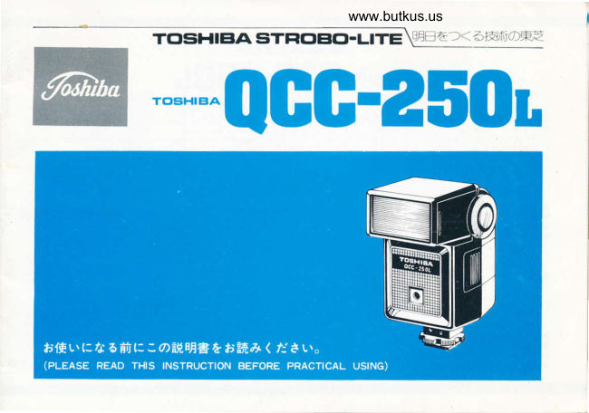
Toshiba QCC-250L User manual
User manual for Toshiba QCC-250L. 25 pages in English. Read the original PDF, download or print a copy without registration.
25 pagesEnglish4.4 MB PDF
Loading your manual…Open PDF directly
Document details
- Brand
- Toshiba
- Model / document
- Toshiba QCC-250L
- Document type
- User manual
- Language
- English
- Pages
- 25
- File size
- 4.4 MB
- Category
- Film cameras
- Document date
- Not specified in catalog
Search available document text
Find a term, then jump to its page in the original PDF. Image-only pages may not be searchable; check the PDF for exact wording and diagrams.
Page 17 · Read text
r  Preparing for photography
    1. Mounting unit onto camera
        Slide the shoe mount into the accessory shoe of- the camera
    and tighten with the shoe clamping ring.
    2. Synchro connection
       This flash unit is provided with a contact for cameras with a
    hot shoe but it can also be made to serve as an ordinary shoe
   mount by connectirrg the synchro cord. [ASM (automatic shoe
    mount) system  l
    (1) Camerc wath a hot shoe
       The contact is automatically connected when the  f lash unit
             is mounted onto the camera.
     l2l  Ordinary Cameras
                         I nsert the synchro cord into the synchro cord socket on the
          flash unit and connect the other end to the synchro termi-
         nal (X contact) of the camera.                              Camera with hot shoe
     .   lnsert it into the "X" terminal if the camera has two synchro
        term ina ls.
   o   lf the camera has a contact selector level, set this lever to the
             position.                                                                                O rd   i                                                                                                          nary/     "X"(For              details, refer to the instrtrction booklet of the camera.)                                     (use                                                                                                synchro                                                                                                                  cord)
    3. Determining the shutter speed
       (i )  Lens shutter cameras
        The flash unit is synchronized to all shutter speeds.
    (2)  Focal plane shutter cameras
        Set to the "X" mark and follow the instructions in the
        camera's book let.
        (The synchronization speed differs according to the camera
          used.   )


                                                                                               Connect'X'
View original page 17Page 18 · Read text
www.butkus.us

r  Photography
   When this electronic   f lash unit is being used, it is possible to                   t the ASA speed with the ASA sPeed
set the aperture to one of two levels (FSS "F stop selector") in               selector switch.
line with the conditions involving the photography (camera dis-           ansar@€ d ista nce wi ndow
tance, depth of  f ield, etc. ).
1. Use in the auto mode                                                       25/15-
(1) Set the ASA speed selector switch to the ASA speed of the                 50/1s =
            f ilm being used.
Q)  Use the auto/manual selector switch to set the f-number  in
      line with the conditions involving the photography. The
     f-number with an ASA100  f ilm is either f2.8 or {5.6. Once
     this f-number has been set on the camera, all you have to
    do is focus.
                                                                                                                                                                                                                 1(3) The distance which has been set now appears in the cover-          2. Set the f-number ustnq
     age distance window.                                                    auto/manual selector switch
      ln the auto mode the coverage distance is indicated by the                                                                                                          3. Coverage d stance lamp      lighting of the coverage distance lamp.
    The effective camera distance is indicated during photo-                                                                     lighted.
    graphy in the auto mode by the number of lamps which
     have lighted.
    For instance, when the aperture has been set to f2.8 with    ASA10O film, the coverage distance will be not more than                                       AUTOo
    7 meters  if the fourth lamp has lighted.
        lf all the lamps light in succession, the coverage distance    o Apertures with auto photography and auto coverage distances      will be not more than 8.5 meters.
(41 The automatic coverage distance does not change even with
     a different ASA speed.                                        Film speed                         Auto coverage distance
                                                   (ASA)     25  50  64-80   r00  200 400  Standard     Wide                                                                                                                             adapter
                                                                                                       t.4   2  2-2.8  2.8   c   5.5  Approx.i 5--8 5m   Approx.1.5.--6m                                                               F-number
                                                                                                                                                                                                                                                                                                .- 3m                                                                                              2.8   4  4-s.6  5.6   8    I  Approx.0.7.- 4.2m  Approx.0.7
                                                          *Use the respective half apertures when employing ASA 64 to
                                                          80  f ilm.
                                                       l5
View original page 18Page 19 · Read text
o Auto warning lamp                                              2. Uss in the manual mode
    This lamp lights to warn of under-exposure when the cover-    (1)  Set the auto/manual selector switch to the center position.
 age distance. which is indicated for auto photography,  is exceed-       "M"  is indicated in the coverage distance window.
  ed.                                                 When the manual mode has been selected, the f-number is
    When the auto warning lamp has lighted, change either the f-        determined by the quide number.
 number or the camera distance and take the photographs again.        f-number = Guide number*Camera distance [f = GN/Dl
 You will achieve better results if you check with a test flash be-       For instance, when the camera distance is 3 meters with
  fore actually taking the photos.                            ASA100 film, the f-number iS set at f8 (guide number
                                                              25 * camera distance 3 m i f8).

                                                                                                  ts=-b--  Gruo

                           Auto warning la                                               ASA,/ orN
                                                                                      25/15-
                                                                                                                 5o/ro l
                                                                                                                            rool.r I        6                                        2OOftaJ            TOSHIEA PHOTO PROOUCTS CO,LTO JAPAN
                                                                                           4oo/27=
                                                                                                                                          8o0.rro I
o Precautions with auto photography                                                  Set the auto/manual selwrrrn  I
  (1) Make sure that the light-sensor window is turned in the                      switch to the center d*rttJ"\                 =F:       direction of the subject.
 Ql Use the flash unit in the manual mode for fill-in flash,
       multiple   f lash or other special photographic effects.
  (3) Use the flash unit in the manual mode for cameras which
       are equipped with a  f lashmatic mechanism.
      (For details, reler to the instructions accompanying your       camera.  )                             EIMI                       o


                                                         t6
View original page 19Page 21 · Read text
o  Coverage d istance with wide adapter3. Using the wide adapter
(1)   lf the wide adapter is mounted when you are using a wide-                                  f2.8                      f5.6     angle lens, then it is possible to obtain coverage up to a 28
   mm lens with a 35 mm camera.                                 Sth lamp        6m            3m
Ql  For attachment, simply mount the wide adipter in the       4th lamp        5m                   2.5 m     groove on the  f lash unit.
*Use in auto mode                                                3rd lamp        4m            2m
  The auto f-number does not change even when the wide      2nd lamp             3.5 m                  1.7 m
adapter                                                                               1st lamp        3m                     1.5 m*The coverageis mounted.distance lamps provide an indication in meters
 with "standard," but when the wide adapter is being used, the  *Use in manual mode
 coverage distance is not equal to these  f igures. See below.         The guide number is 1g with an ASA10O  f ilm.

                                        o Guide numbers based on  f ilm speed        (With  f ull light)
                                               ASA speed of  f ilm           25    50    100  2oo I 4oo
                                                       Gu ide number                    I     13    18    25    36
                                                     4. Test method and open flash
                                                             With a test  f lash or open  f lash photography, depress the open
                                                                                                                                                        f lash button after the lamps have lighted.
       rg         H+
                                                                -\
                                                     t8
View original page 21Page 22 · Read text
www.butkus.us

5. Bounce photography
  When you are taking photographs indoors, you can aim the
flash unit at the ceiling or at a wall -  instead of directing theflash directly at the subject - and achieve a soft lighting effectwhen the light is ref lected.
   The flash head of the unit may be set at the 0o,60o,75" and
90' click-stop positions.
o Auto bounced light photography
(1) Once you have decided on the subject for your photograph,
     point the  f lash head at the desired bounce angle.
l2l Auto operations are generally the same as those for auto
     photography.
    The auto coverage distance for bounced light must be
     greater than the total distance between the  f lash unit and
      reflected surface and between the reflected surface and the
     subject. This means that a low f-number is normally ap-
      propriate.
(3) You will achieve better results if you perform a check with
    a test  f lash before actually taking the photos.
o Manual bounced light photography
  A great deal depends with manual bounced light photography
on the distance and conditions involving the reflection surface
(color, reflectance, etc.) and so it iswiser to proceed after taking
a test photo.
Bounced light precautions
(1) Remember that the subject and its surroundings may
     change color when you are taking pictures in color because
     of the effects of the color of the reflecting surface.
Ql Take care not to allow the subject to enter directly into the
     range of the bounced light angle with bounced light photo-
     graphy.


                                                      t9
View original page 22Page 23 · Read text
I  Hints on taking better photographs                              I  After-salesserYicing
   The guide numbers and exposure table indications are an ex-      This electronic flash unit was manufactured under strict
posure factor and a guideline for determining the aperture sim-    quality control conditions. However, if it should break down, do
ply. However, the following points should be borne in mind due   not touch the internal mechanisms but contact your dealer or
to differences in the photography conditions.                   send it to one of Toshiba's service stations together with the
(1) An average overall light reading is taken with auto mode    warranty.
     photography, and so you will achieve better results if you       Toshiba may not be able to accept requests for repairs  if you
    open the lens aperture by one stop more than the specif ied    have disassembled the flash unit yourself.
    f-number if there are white walls or glass windows. for in-      The warranty period extends for 1 year from the days of pur-
      stance, which ref lect the light in your line of view.              chase.
    Stop down the lens aperture by one stop more than the       Repairs will be undertaken at cost if the warranty period has
     specified f-number if there are black curtains or other    expired or if the warranty is not presented.
      similar objects which ref lect very little light in your line of
     view.
Ql   lf the light sensor is prevented from being obstructed, a dif-
     fused effect with tracing paper or a white handkerchief can
    be achieved. Take a test photo since the automatic coverage
(3) distanceOpen theis lensreduced.aperture by one or two stops more than the
     required f-number when taking photos in a large room
    where very little light is ref lected or outdoors at night when
     the  f lash unit is set to the manual mode.
I  Cautions
(1) Avoid using the flash unit in temperature extremes (over
    40oC. under -10"C) since these will adversely affect the
      internal parts.
Ql  Never attempt to disassemble the unit if it breaks down.
     This could be dangerous.
(3) Do not exposure the unit to humidity or rain or sea water.
*The design and specifications given in this instruction booklet
 may be revised without notice.


                                                  20
View original page 23Page 25 · Read text
H.25HH ftffifiA+i
 4+r       Tr07 HHA[i6EfrtE.l TE e 615€ €;f; R H   03(585)3466ft)
 HHffi-trXFfi  'T107 RHetJi6trfirE I TE e 615+ €;f; R H   03(5s5)3461fft)
 Rfrffi-trXFf(      HHA[i6trrFiE I TE e 615€ €;i6  H   03(s85)3461ft) tllEH*E['  =107T53r                           t TE I &338 E;6   Ht  Itn 06(454)2381ffi)
 hfrtrH#Ffr       ^[EiFtittrtii+&fr tr fr'FtrR 1 rH 20&.28? €;f;  &fr tr  052(e5l)6841ft)
 tEFilE,#Ff  T8r0=46r ?Elff ffi+*trF!R 2 TE 4 6 1 +  €;6   lE  IE 0s2(72r)521lffi)
 {rl€E'*Ff'   T983{ilj6ffiflrtrI 2TH 2&tE     €-ifi    {dl   fi  0222(505336fit)
 fL|!fr€'*Ff  T064 fLDtL ft'+ 4 Effi z *E r T E 13# €-rf;   +L {B 01r(512)3866ft)
 EHH#_Ffi  T73O Ii Hft'HE.[EtrI 2Ttr35# 1€   €,if, E H  0822(63)0106ft)

TGISHIBA PHc'TCl FFTC'tr,UCTA CCt., LTtrr
No. 9-1 5, 1-CHOME, AKASAKA, MINATC-KU, TOKYO,JAPAN
                                                OPRINTED- IN JAPAN
View original page 25From the M. Butkus archive. Original publisher and archive notices are retained.
Check the model and edition against your equipment.
PDF verified 2026-10-10.