Flashes & lighting
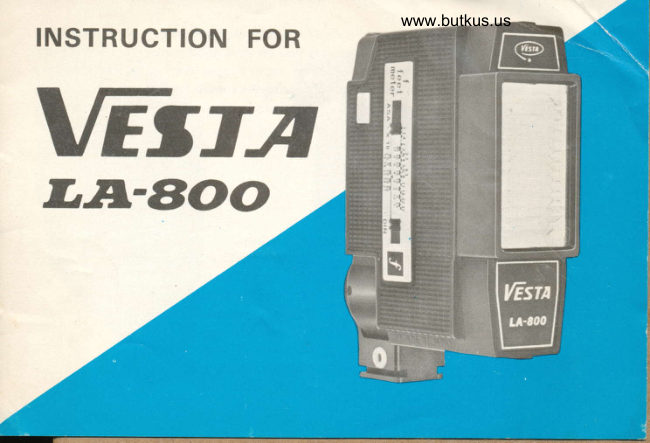
VESTA LA-800 flash User manual
User manual for VESTA LA-800 flash. 9 pages in English. Read the original PDF, download or print a copy without registration.
9 pagesEnglish2.0 MB PDF
Loading your manual…Open PDF directly
Document details
- Brand
- Vesta
- Model / document
- VESTA LA-800 flash
- Document type
- User manual
- Language
- English
- Pages
- 9
- File size
- 2.0 MB
- Category
- Flashes & lighting
- Document date
- Not specified in catalog
Search available document text
Find a term, then jump to its page in the original PDF. Image-only pages may not be searchable; check the PDF for exact wording and diagrams.
Page 2 · Read text
We thank you for your purchase of the VESTA electronic flash unit, "LA" series model,
for your flash photography, and congratulate you on your good choice. In order for you
to enjoy maximum eff iciency and performance, let us suggest that you read this manual
thoroughly and make yourself fully acquainted with the superb features of the unit. This
model offer extreme compactness, sturdy construction, easy, simple and safe operation
yet powerful light output.


First, please learn the name of each part and its function.
 1. Flash window (Diffuser)             9. AC cord connector socket
 2. Open flash button                 10. AC/DC switch
 3. Exposure Guide scale                          1 1. Voltage selector lever
 4. Synchro cord socket               12. Battery case (Four penlite Batt.)
 5. Hot shoe                        13. Neon Lamp
 6. AC cord                        14. Battery cover
 7. AC plug                        15. Clicstop setting
 8. AC cord connector                16. Synchro cord
View original page 2
Page 4 · Read text
Venmo @mike-butkus-camera  Ph. 2083
PayPal Name  Lynn@butkus.org      www.PayPal.me/lynnbutkus
View original page 4
Page 5 · Read text
POWER SOURCE
LA800 operates on either household current (AC) or on DC with four (4) pieces of
standard penlite batteries. For AC operation, 22O-24OV type and 100-12OV type are
mdde available.

                                                                                  Digitally signed by Mike Butkus
                                                              DN: cn=Mike Butkus, o=Butkus camera manuals,
                                                                     ou=butkus.org, email=mike@butkus.org, c=US   Mike Butkus        Date: 2023.11.25 20:27:51 -05'00'
A.C. OPERATION
1. After placing switch to AC position, set                                                                                                    I  the voltage lever to 10O-120V or
   22O-24OV by pin.
2. Connect the end of cord to flash unit, and                                                                 fi
   the other end into AC outlet.
                                    3. When using or testing the unit with AC,
                                  neon lamp will glow after 6-7 seconds,
                                    and you can push the camera shutter (or
                                       open flash button.)
4. Set F-stop value on your camera is accordance with the reading on the Exposure
   Guide scale (See EXPOSURE GUIDE SCALE)
5.  Release the shutter release button of your camera for picture taking so that the flash
    unit synchronizes with the camera shutter.
View original page 5Page 6 · Read text
www.butkus.us                  \i
    DC OPERATION
      1. Insert to penlite batteries (Eveready No.915, AA size, or Alkaline batteries into
         compartment as shown noting the correct polarity and close the cover.


I     2. Turn the switch to DC. Arising cycle tone will be heard, showing that high power
I         capacitor  is loading. Neon lamp will        fully, when unit is ready for flashing.


         Even               before      3.                     the
                 case,             this                   the                             light-neonoutputlampwillgoesnot on,be sufficient.the unit may flash if the shutter is released. ln
      4. When not using or when finished, make sure to switch to AC position. (OFF.)
    REPLACEMENT OF BATTERIES
     When it takes too long for the neon lamp to light after the switch is put on, the batteries
       should be replaced. Take out the exhausted batteries, and replace them by fresh ones.
View original page 6Page 7 · Read text
MOUNTTNG THE UNIT TO CAMERA
1. FI.ASH POSITIONS


    positions (right and left) as indicated above, with smooth click-
   stop setting of the camera or camera attachment bracket.      www.butkus.us
2. Plug the synchro cord into the contact of the camera. (X or M.)
OPEN FLASH
To test firing for non-synchronized open flash, just press lightly theOpen Flash button
after determined that the Neon Lamp is lighted enough.
NEON LAMP
For each flash, make sure that the Neon Lamp is brightly lighted which means that the
condenser is properly charged and the unit is ready for flashing. Flashing without fully
 lighted Neon Lamp means that the condenser is not yet properly charged, and certainly
cause under-exposure.
View original page 7Page 8 · Read text
\>                                           www.butkus.us
SHUTTER SPEED
The duration of a flash is extremely short, and in the case of a lens shutter, the camera
and VESTA LA€O0 are perfectly synchnized up to the lightest speed when the synchro
contact is set at X.
Forexample,even atll2SOsec.thetotal lightoutputcanbeutilized,irrespectiveof   the
guide number. With a focal plane shutter, use the X mark on the shutter dial or shoot at
1/60 sec. or slower speed.
EXPOSURE GUIDE SCALE


                                                    1. TRIANGULAR MARK
                                                 2. SLIDING SCALE
To obtain proper f-stop value to be set on your 3. ASA/DIN NO.
camera, a convenient Exposure Guide  scale is  4. f-STOP VALUE SCALE
provided on the body of the unit.                  5. DISTANCE SCALE
First, again the triangular mark 1. on the sliding scale 2. with the ASA/DlN No.3. of the
f ilm loaded in the camera. Measure distance between your camera and subject. Read the
f-stop value 4. aligned with the distance 5. indicated in feet and meter on the sliding
scale, and set the f-stop value on your camera.
View original page 8Page 9 · Read text
SPECI F ICATIONS
GUIDE NUMBER:          80 (ASA 1O0 in feet)
                        40 (Kodachrome ll in feet)
                        24 (ASA 100 in meter)
FLASH DURATION:              1 /2O00 sec.
COLOR TEMPERATURE:   5700" kelvon.
REFLECTOR COVERAGE:   Horizontal 50"
                                Vertical 50o
                                                       sec. (DC)RECYCLING TIME:        6-7 sec.t  (AC) 6-8
POWER SOURCE:        AC 100-120V or 22O-24OV
                    DC four (4) penlite batteries.
                              or Alkaline batteries.
NUMBER OF FLASH:         Penlite battery
                             about 40 flashes.
SIZE:               35mmx80mmx100mm
WEIGHT:                  200 grams (without battery)
ACCESSORY SHOE:          Retractable & Swivel (180') type.


                                                                      Printed in Japan
                                               +
View original page 9From the M. Butkus archive. Original publisher and archive notices are retained.
Check the model and edition against your equipment.
PDF verified 2026-10-10.