Flashes & lighting
Vivitar 4600 Flash User manual
User manual for Vivitar 4600 Flash. 6 pages in French. Read the original PDF, download or print a copy without registration.
6 pagesFrench0.8 MB PDF
Loading your manual…Open PDF directly
Document details
- Brand
- Vivitar
- Model / document
- Vivitar 4600 Flash
- Document type
- User manual
- Language
- French
- Pages
- 6
- File size
- 0.8 MB
- Category
- Flashes & lighting
- Document date
- Not specified in catalog
Search available document text
Find a term, then jump to its page in the original PDF. Image-only pages may not be searchable; check the PDF for exact wording and diagrams.
Page 2 · Read text
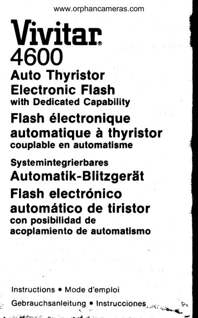
www.orphancameras.com
Vivitan4600
Auto Thyristor
ElectronicFlash
with Dedicated Capability
Flash6lectronique
automatiquei thyristor
couplable en automatisme
Systemintegrierbares
Automatik-Blitzgerdt
Flashelectr6nico
autom6ticode tiristor
con posibilidad de
acoplamiento de automatismo


Instructionso Mode d'emploi
Gebrauc hsan Ieitung o Instrucoiones,-{ ;                                              "..r*o*,
View original page 2Page 3 · Read text
www.orphancameras.com


To maximizef lash range in bounce positionsusing      wide  panel, the  effective gu ide nu mber and
the motorizedzoom head, head should be in the     maximum auto ranges are approximatelyhalfthat of
Telephoto position                                   the 35mm ("35") position Referto the specification
Avoid colored reflective surfaces when using color       section following
film, since bounced lightwill be influencedby such
colors and affect the exposure accordingly
Follownormalflash and camera settingprocedures
as previouslyexplained                   Manual flash operation
                                                     1 ) Set your camera to the manual mode (or flash
Eyelightpanel                                 synch mode)
                                                         2) Set your camera shutterspeed manuallyto theThe eyelightpanel (14) has two f unctions:                                                        correct flash shutter speed as outlinedin yourWhen photographingpeople. it adds a pleasing                                              camera instructionbookhighlightto your subject'seyes and fills in shadows
when using your flash in the bounce position Place       3) Set index line on the film speed selectorswitch
the retainingclip of the panelover the top of the flash        on the  f lash slide rule calculator diaI to the
head and raise the panel so that  it faces your        ASA/DlN speed of the film you're using.
subject This will reflect a small portion of the       4) Set mode on "dedicated"flash module to "M"
bounced light directlyon your subject                                  ( m a n u a l p o s i t i o n )
With direct flash usage and the panel in the down       5) Focus on your subject and note the flash-to-
positioncovering the flash head lens, the eyelight        subject distance Locate this distance on the
panel provides extra wide angle 28mm  flash          slide rule calculatordial distancescale
coverage Zoom head must be in the "W" (Wide       6) Set your lens to the f -stop locatedon the aperture
angle) position Open camera lens one full stop         scale on the slide rule calculatordial, directlv
widerthan indicatedby calculatordial,when used in        above your flash-to-subjectdistance
manual flash operationmode                                                         7) When the flash is charged and ready,the visual
                                                and audible ready indicators will function as
Super wide panel                               discussedpreviously
(lncluded with motorizedzoom head)     B ) N O T E :
This panel is used to cover a21mm lens The zoom         There  is,-nc*sf,1?lUt6ntlight indication in the
head must be in the "W" (Wideangle)positionwhen      m a n u a l m o d e W h e n y o u ' r e u s i n g t h e 2 8 m m
usingthis accessory,NOTE: When usingthe super        wide angle panel, you must opeftryourlens one
View original page 3Page 4 · Read text
www.orphancameras.com
                                        Description of controls
                                                      1 ) -10o Releasebutton
                                                           2) Bounce angle indicatorscale
                                                             3) Release button for flash head
                                                           4) Film speed indicatorswitch
                                                           5) ASA/DlN film speed scale
                                                           6) Aperture (f-stop) scale
                                                             7) Distance scales (feet and meters)
                                                      B) Automatic ranges
                                                     (Red, Blue and Orange lines)
                                                             9) Control switch -  motorized zoom head
                                                     1 0) Calculatorlight button
                                                     1 1 ) Three-positionpower switch
                                                     12) Flash ready light/open f lash button
                                                    13) External power receptacle
                                                    14) Eyelight/wideangle panel
                                                     1 5) Battery compartment cover
                                                   16) AP-1 batteryholder

                                                     1 ) Slide open batterycompartmentcover (15) and
                                               remove AP-1 batteryholder(1 6) Insertfour "AA"
                                                         Alkalineor Nickel-Cadmiumbatteriesor a Vivitar
                                              NC-3 battery pack.  lf using batteries, follow
                                                        position markings on the AP-1 holder lnsert
                                                          batterypack in batterycompartmentand replace
                                                        cover,
                                                           2) Attach DedicatedModule per module instruction
                                                  manual.


      f ull stop wider than the f -stop recommendedon     MFS-1 as shown in the MFS-1 inst/uctionsheetwith
   the flash aperturescale f or the given camera-to-      the following exceptions:
   subject distance.                                                           lf you want to  retain your dedicated interface
                                                 connections with your camera do not attach the
Autowinder operation                           flash swivel shoe.
(not applicableto Canon cameras)        Follow general instructions given  in the 4600
                                                        instructionbook with the followingexceptions: lf using your flash with an auto-winder(up to 2 fps)
the flashwilldeliverup to 4 flashesin sequenceat 2       a) Close down aperture4 stopsf rom the auto f -stop
fps Allow 30 seconds for flash to recycle between       chosen in instructionpoint 6
sequences. The auto-winder setting also reduces      b) Canon camera lenses must be set manuallyand
manual output to 1 132power (-5 f-stops)for fill light        the 4 f -stopcompensationappliesas well Do not
applications                                             set the lens in the "A" position,
Follow manual instructionspreceding,with these       c) For Olympus and Contax TTL cameras,use auto
exceptions:                                  modes on module (not TTL position)and set f -
 a) Set cledicatedmodule to yellow ^r, on position         stop per a) above
 b) Refer to flash-to-subjectdistance on calculator      d) For Nikon EM, use Auto modes on module (not
   scale and note lens aperture indicatedat this      EM position)and set f -stop per a) above,
   d istan ce                                                                           lf you decide to use the swivel shoe with the flash
 c) Set lens 5 f-stops wider than indicated on      "on camera" you must set your f lash shutterspeed
   calculatorscale (see chart)                      manually and you  will not receive dedicated
                                                    viewfinderinformation.You can stillutilizeautomaticC a l c u l a t o r s c a l e r e a d i n g     5 6     8     1 1    1 6    2 2
C o r r e c t l e n s s e t t i n g :         1 2    1 4     2     2 8     4           flash  operation as  discussed  in  the  general
                                                   operating instructionspreceding.NOTE: The one f-stop compensationrequirement
for 28mm wide angle panel also applies The     To utilizefull dedicated macro flash interfacewith
sufficientlight indicatorwill light,but this should be      the f lash off camera,attach the DSC- 1 to the module
disregard ed                                    and connect it to the flash unit,You can now use the
                                                   swivel shoe and  still retain full camera/flash
Macro flash sensor operation               dedication
 Follow the general mounting instructions of the

                                                           \
View original page 4Page 5 · Read text
www.orphancameras.com
3) Make certainpowerswitch(11) is in the "Off"         informationpertainingto your particularcamera
   position,then insertmountingfoot into camera       model.
   hot shoe and rotatethumbwheelto the riohtto      B) The power switch (11) has three operating
   lock unitin place.                                 positions:"Off","On" and "AutoZoom".When
4) Set indexlineon filmspeedswitch(4)to match        usingthe standardhead,the "On" positionturns
   film speedin camera.                             the flashon.However,thef lashis alsoturnedon
5) Set zoom controlswitch(9) to desiredposition         in the "AutoZoom"positionso,whenturningthe
   ("W","35","50",or "T", explainedlater).NOTE:         unitoff, makecertainthe switchis in the extreme
  When usingstandardhead,set switchat "35"            left "Off' oosition.                                       /
   position.                                        9) Turn the powerswitchon and waitfor the flash
6) Threeautomaticoperatingrangesare provided,       ready light (12) to glow. lf switchedon, the
   indicatedby the Red,BlueandOrangelines(B).       module"beeper"will also soundintermittently.
  Selectdesiredauto range/f-stopcombination,     You are now ready to shoot. The 4600 is
  usingthe appropriateauto rangeline and the       equippedwith an energy saving circuit to
  correspondingf-stopon the scale (6) directly       conservebatterylife.lf you do not fire the flash
  abovethe verticalline.                        and powerremainson, the flash readylightwill
                                          changefrom Red to Greenand the powerwill  EXAMPLE:Withthe unitsetfor 100 ASA/DIN21
  and at the "35" position,the automaticworking       automaticallyturn off until the controlcircuit
  rangeis f rom6.6ft.(2 m) to 50 fi.(15 m) withan f -        determinesthat the capacitor has lost the
  stop settingot f -2 in the Red auto mode.             equivalentof onef-stop(-1EV).At thispointthe                                            power will be restoredautomatically,and the  The correspondingauto mode,in this example                                                     flashreadylightwillchangefromGreenbackto  Red, must also be set on the dedicated                                            Red,startingthe normaloperatingcycleagain.  module.Incorrectmodulesettingcan resultin
  improperexposure!                        Sufficientlight indicator
  NOTE: Not applicableto TTL (Through-The-   A visual (Green Light) and an audible (continuous
  Lens)operationwith OlympusOM-2,OM-2N,     "beep" tone) sufficientlightindicatoris incorporated
  Contax 137 and 139 cameras. Refer to        in  the  dedicated module (switchable). These
  d e d i c a t e d m o d u l e m a n u a l  l o r  s o e c i f i c      indicators operate in all three auto modes -  Red,
   instructions.                                 Blue or Orange.To check for sufficientlight,wait for
7) Refer to  dedicated module manual for      the flash ready lightto glow, aim the flash at subject

                                                                                      '.qta             -

 External power supply operation          Automatic f-stop settings &
Whenusinganyof theexternalpowersuppliessuch     corresponding ranges
 as the HVP-1, theSB-4orthePPG-1, whichpluginto
 external power supply receptacle(13), fresh              ASA 1OO/    Normal
 batteriesmust be installed.These batteriespower               D I N 2 1     35mm
 the low voltagecircuitof the dedicatedmodule.The    Red mode         2       6-50'(2-15m)
 use of externalpower suppliesextends internal    Bluemode        4       3 - 2 5 '( 1 - 7 . 6m )
 batterylife.                               Orangemode     B      2-12',(0.7-3.8m)
                                                                      Standard
 Using the Vari-PowerSlave                                50mm
 with the 4600                          Red modef-stop2          8-60'(2.5-18m)
 Whenusingthe VPSreferto the followingchart:      Blue modef-stop4          4-30'(1.2-9m)
 Varioowerswitchoosition:  Full   1 /2    1 /4    1 /8  1 /16     Orangemodef-stopB      3 - 1 5 '( 1 . 0 - 4 .m5 )
 Actualoutputof 4600:      Full   1 /B   1 /16   1/32  1 /64                              Wide
                                                   2Bmm
Specifications                        Red modef-stop2         5 - 3 5 (' 1 . 5 - 1 m0 )
 Guide number ASA 100/ft (DlN 21lm)             Bluemodef-stop4         2-18'(0.7-5.3m)
                                        Orangemodef-stopB      1.6-9'(0.5-2.5m)Normalhead:100(30)(35 mm)
 withEWiA-1'.70(21)(28 mm)                                          Superwide
 withSUPERWIDE(FA-3):50 (15)(21 mm)                                       2 1 m m
                                      Red modef-stop2         5-25'(1.5-7.6m) Motorzoom head:                                            Bluemodef-stop4         2-13'(0.7-3.8m) Standard:120 (36)(50 mm)                                        Orangemodef-stopB      1 . 6 - 6(' 0 . 5 - 1 .m9 ) Normal:100 (30)(35 mm)
Wide:70 (21)(28 mrn)                                                        Tele
Tele:140 (42)(105mm)                                             105mrn
Superwide:50 (15)(21 mm)                  Red modef-stop2         10-70'(3-21m)                                                                             dq                                            Bluemodef-stop4         5 - 3 5 (' 1 . 5 - 1 m0 ) Barebulb:60W/Secmax at full oower                                         Orangemodef-stop$   ,,r,  4 - 1 8 '( 1 . 3 - 5 .m3 )
 Flashduration
 Manual:1 /'1,000second                       Sensor measuringangle
Automatic:1/1,000- 1/30,000second             Approximately1B'
View original page 5Page 6 · Read text
www.orphancameras.com
and press the open flash button (12). lf light is    NOTE: lf usedmanually,zoomheadwillreturritothe
adequatefor correctexposure,the green module     positionset on zoomcontrolswitchwhenthe power
indicatorwill glow, accompaniedby a continuous    switchis movedfrom"On" to "AutoZoom"oosition.
"beeeeeep"toneif audiblesignalis "on",lf sufficient     Selectdesiredauto rangeas previouslydescribed
lightsignal(s)are not evident,usean automodewith    and you are readyto shoot.
a largerf-stopsetting,or decreaseflash-to-subject
distance.                            Bare bulb head
Interchangeableflash heads               This head offersthe creativeadvantageof being                                               ableto positionone or more 4600 unitsto effecta
To removehead,firstturn powerswitchto the "Off"     "naturallighting"look.The barebulbunitshouldbe
position.Holdbaseof unitfirmlywithone handand     thoughtof as a portableelectronicsubstitutefor theuse thumbto push releasebutton(3) downwards.                                             standard incandescentlight bulb. For example,
When button is fully depressed,slide flash head     placedinsideof a table lampshade,the bare bulb
forward with other hand to remove. To install     unit will create a pleasing,naturaleffect.A major
alternatehead,reverseprecedinginstructions.      advantageis thatbarebulbunitsarecompatiblewith
                                                other on and off-cameraflashes,all balancedfor
Motorized zoom head                       daylightfilm. Since bare bulb light output is
This unit providesoptimumlightingbecausethe    measuredin power(60watt/seconds),it is helpfulto
head can be zoomed in or out automaticallyto     use an electronicflash meter to helo determine
narrowor widenthe lightpatternto malchthe lens     correctexoosures.
you are using.The motorizedzoomheadshouldbe
set to matchthe lens beingused on your camera,   Bounce flashi.e.:For 28 mm lens,set controlswitch(9) to "W"
(Wideangle).For35 mm lens,setswitchto "35".For    By "bouncing"flash outputoff reflectivesurfaces
50-55mm lens,set switchto "50".For 105 mm to     such as ceilingsor walls,subjectscan be more'135  mm lens,set switchto "T" (Telephoto).Angleof      softlylighted,creatingvariedeffects.In additionto
                                               thenormalstraightahead(0") position,the4600haslight coveragewill complyto these settings.The
power switch (11) must be in the "Auto Zoom"    up anddownclick-stopbouncesettingsat 45o,65",
positionto activatemotorizedzoom head. lf the     90" and -10o for straight-onflash parallax
powerswitchis in the "On" position,the mctorized    correction.Horizontalrotationpermitsbounceshots
                                                         in 15o incrementsfrom straightahead(0o)to 90"zoomhead can be shiftedmanuallyto any of the
previouslynotedpositions.                         rightor 180'left.


                                                                                                       .sik__
                                                   *rc*                    >!l_ta
                                L,*.
Recycle time (average)                       Bounce
                     Automatic Manual       Horizontal                                     '124 A A a l k a l i n e( A P - 1 )      0.2-12s       s             right:0, 15, 30, 45, 60, 75, 90o
NC-3                   0.2-6.5s    6.5 s              left:0, 15,30, 45,60, 75,90, 105,120,
                                                1 3 5 ,1 5 0 ,1 6 5 ,1 8 0 "
                                      Full                                                    Vertical
                Main          Power        -10 lock.:0, 45,60, 75,90'        PPG-1   Unit    R.T.   Flashes     .NOTE:                                        Whenthe headis set at -10 position,           Atk.    Atk.    0.2-6    200                                                 the head does not move horizontally.pp^_1     Alk.   NC-3   0 . 2 - 5    1 1 0
        NC-3   NC-3   0.2-4    B0        Motorized zoom head capability
        NC-3    Ark.    0.2-5    1 10        4 positionswitchsetting(W/N/S/T)
                                                Capabilityof couplingwith,supermodule.
        sB-4    Atk.    15     500       Energy saving
        sB-4  NC-3    1 2     1 0 0                                       Ready light
Numberol flashes(average)                Red LED
                    Automatic Manual       llluminatedcalculator
4 AA alkaline          up to 700    90        By push button
NC-3                up to 300    40                                       Open flash button
Angle of coverage                                              Accessoriesincluded
                          Vertical Horizontal                                           EW/A-1...regularheadonly
Normalhead(35mm)      45"       60"         AP-1...bodyonly
with EW/A-1(28mm)       53"       70"        Superwide...motorzoom head only
with FA-3 (Zlmm)           67"        85'
Motorzoom head
Standard(50mm)          34"       46"
Normal(35mm)                                     A                                         AJ R O       6 0 0
Wide (28mm)           *s1r     53"        70"                              *S. Wide (21mm)            67"
Tele(105mm)              20.
View original page 6From the M. Butkus archive. Original publisher and archive notices are retained.
Check the model and edition against your equipment.
PDF verified 2026-10-10.