Film cameras
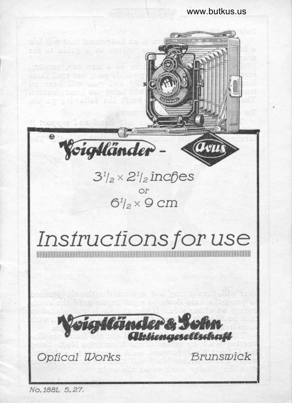
Voigtlander Avus User manual
User manual for Voigtlander Avus. 17 pages in English. Read the original PDF, download or print a copy without registration.
17 pagesEnglish4.9 MB PDF
Loading your manual…Open PDF directly
Document details
- Brand
- Voigtländer
- Model / document
- Voigtlander Avus
- Document type
- User manual
- Language
- English
- Pages
- 17
- File size
- 4.9 MB
- Category
- Film cameras
- Document date
- Not specified in catalog
Search available document text
Find a term, then jump to its page in the original PDF. Image-only pages may not be searchable; check the PDF for exact wording and diagrams.
Page 1 · Read text
www.butkus.us


          3tlr* 2'lrlncQes
                    or
             O'lrx 9 cm
Inslrucllons for useililililililillililililililiiiiiiiiiiiiiiiiiiiiiiiiiilllllllllllllllliilllillllllllllllllllllllllllllllllll


    W
OpIlcoI Dorks            F.runswlck
View original page 1Page 2 · Read text
Introduetlon
  A Voigtliinder camera  1S an instrument that will last
 a lifetime. This booklet  is written as a guide to the
 user of such a camera.
  Do not look on a camera as a new toy, turning,
 screwing and moving every possible part, but read these
 lines of advice very carefully and you will have n<r
 trouble, and the instrument will bring you great pleasure.
Therefore kindly take to heart the following points.
To open tlre eamcra lor use
   Take the camera in the leit hand and support it
with the right as illustration (Fig. l).  With tlie left
forefinger press the button underneath the handle. The


                                   Fig.l
base will then srving out against the thumb, proceed
to press the base down to right angles until the struts
engage on either side. If the thumb is not placed in
that position,  it may cause the base to drop down with
considerable force and this may strain the hinges.
  The next operation is to pull out the front, see illu,
stration No.2, by means of the finger grips No 8. Bring
the U front No.7 forward until it comes to a definite
stop. The indicator No.9 will then be exactly in line
with the infinitv mark o<> on the scale.
View original page 2Page 3 · Read text
www.butkus.us
  To focus the camera on close objects, pull the rack
and pinion knob No. l0 (Fig.2) outwards. This action
unlocks the rack and pinion and focussing can now be
proceeded with either by using the scale on which the
distances are engraved or the shutter can be opened
for time action and the object to the photographed
can be focussed on the focussing screen.


                                Mike Butkus  Digitally                                                                                                                                                                                          DN:ou=butkus.org,Date:cn=Mike2024.05.06signedButkus,email=mike@butkus.org,by21:23:11Mikeo=ButkusButkus-04'00'camera manuals,c=US


                                 Fis,2
   After the critical focus is obtained push the rack
and pinion knob back again into its locked position.
    If the double extension of the camera is required to
be brought into operation pull out the front by means
of the two finger grips No-8 to the extreme length of
the baseboard.
  The focussing screen Fig.3 is provided with a hood.
A small lever keeps the flap of the hood in position.
The particular feature of the focussing screen is that
a new glass can easily be inserted if the user should
have the misfortune to break it.  If the accident should
happen in an out of the way place rvhere no ground
glass screen can be obtained, an unexposed plate can
be used temporarily. Care must be taken that the
emulsion side of the plate is towards the lens, otherwise
the register between slide and screen will be different.
View original page 3Page 5 · Read text
It is also advisable when inserting the new ground
glass screen to cut the corners a trifle to allow the air


                                Fig.3
to escape out of the bellows space when the camera
is closed.
Depth ol Focus
  The Anastigmats mounted to our cameras  are so
calculated that with full opening good definition is ob,
tained up to the edges, providing the objects to be
photographed are approximately in parallel line to the
camera.
  In cases where several objects have to be photo,
graphed which vary in distance from the lens, and they
have to appear with good definition on the plate, then
it is essential that the diaphragm should be stopped
down. To see how far one has to stop down it is best
to focus on the focussing screen.
  The table herewith gives an approximate idea how
far to stop down and the approximate distances brought
into focus when the diaphragm is stopped down.
Iris lDlaphragm
   'I'heThe irisiris diaphragmdiaphragm servesserves inin thethe firstfirst placeplace toto inzint
creasease thethe deoth.depth. Secondly.,Secondlv. itit mustmust alsoalso bebe emolovedemployed
whenwhen thethe risingrising oror slidingslidinq frontfront isis broughtbrought intointo operatoperation.
This is easily understood.
View original page 5Page 7 · Read text
Example: The front is raised to its fullest margin 3/s"i
 It has then to cover a bigger margin to the bottom
 edge of the plate. By stopping the diaphragm down this
 is secured. This also applies when using the drop or
 sliding front.
   The diaphragm    provided with a lever, pointer and
 scale. The scale is engraved with the standard diao
 phragm values.
 Tlre purpose ol ttre rlslng and sllding lront
     If Architectural subjects are to be taken such as
 Churches etc. to keep the foreground out, the camera
 front has to be raised. See Fig.2. The milled knob
 No.5 controls the rising and drop front. For Horizontal
 views the sliding front is operated. Milled knob No. 11.
   The amount of rise provided on the camera is about
 31a". The drop is'1n", and the sliding rnovement allows
 for a decentreing of about  bl.,;." each way.
  We once more emphasise that the covering power
 of the lens is calculated only to give critical definition
 to the edges in its central position. This position is
 marked on the camera front.
   The more the lens is decentred the more the dia,
 phragm has to be stopped down.
    Particular care has to be taken when closing the
 camera to see that the front is centre both wavs. Never
 attempt to close the camera otherwise.
 Exposure
   The right exposure, which is the most essential factor
 in Photographl', depends on three points:
            1. Opening of the Iris Diaphragm.
            2. Speed of the plate.
           3. Value of the actinic light.
  We advise the use of an exposure meter for the
 above purpose.
 Shutter
   The shutters fitted to these cameras are the Embezet.
'Ibsor and Compur. Instructions herewith.
View original page 7Page 8 · Read text
www.butkus.us
Embezet- Shutter (Fig. 4)
   Instantaneous exposures: The Embezet,Shutter is an
automaticqlly w-orking shutter and does not need adjust,
ment. - The release is worked by pressing lever 14 oi thewire,release which is fitted into 15 (Fig.+). The speed
 is regulated by means of speedodiallT, and as sliewn
by the markings instantaneous exposures can be given
from 1/26 up to t/roo th second, it 1s only necessar-y to


                                 Fig.4
r4just- the wanted speed on the dial by turning it round.
This done, the releaCe,lever 14 or the wirerrelease fitted
into 15 is worked and the exposure made.
   Tim_e'exposures: Turn dial 17 to the right until
letter:er TT isis oppositeopposite thethe pointerpointer onon thethe dial.dial. The first
action of thC finger,release (lever) 14 or wire,release
gpens the shutter; a second pressure closes it  again,
Lette-r t  signifies short time expbsures. By first adjusting-finger,the dial to 17 and ,then pressing down eitherrelease 14 or wire;release the shutler opens and remiins
thus for such time as the pressure is exercised.
Ibsor-Shutter (Fig.5)
  The Ibsor-Shutter is an automatically acting shutter
requiring no setting. To release, press down finger,
View original page 8Page 9 · Read text
release 14 (Fig.S) or work wirerrelease fitted into 15.
Speed is regulated by dial 17 and according to the
speedrmarkings instantaneous exposures of from  l second
upup 1/1s6th1/1s6th secondsecond areare possible,possible, itit onlyonly requiresrequires toto turnturn
round speedrdial and to arrange the <iesired speed.
This done, press finger or wirerrelease.
   Time,exposures: Turn dial to the left or right till
letter T appears opposite the stationary pointer. The


                         www.butkus.us

                                  Fig.5
first action of the finger or wire, release opens the shutter
the second like movement, shuts it again. Letter B
stands for shortrtimezexposure. By adjusting dial 17
at B and pressing finger 14 or wirezrelease the shutter
opens and remains open for such time as the pressure
is exercised.
Gompur- Shutter (Fig. 6)
  Time exposures: Set dial 79 on Z. Exposure is made
either by pressure on wirerrelease, which is screwed
into nozzle 18, or on fingerrrelease 20. The shutter
remains open until the second pressure is given when
the leaves close.
   Brief exposures: For time exposures of short duration,
say up to five seconds, place the dial 19 on D. The
View original page 9Page 10 · Read text
www.butkus.us

shutter opens bv pressure on wire or finger'release and
rimuins ope.t soiottg as this pressure  is retained. Directly
ih" pr"s*e is relealed the shutter closes and completes
the exposure.
   Caution: The shutter is entirely automatic for time
and brief exposures and consequently |".t".t 22 is locked   no attempt must be made to use this lever for such
"ttdexposures.
                           2:


                                   Fig.6

   Instantaneous exposures: For instantaneous e-xposures
first of all see that dial 19 is on lL/. Unless this is in
its right position setting lever 22 -cannot be moved.   Set aiit 24 to the deiired speed then press the setting
lever 22 down to the limit of motion. The shutter is
then discharged either by pressing the wire'release 18
or fingerrrelease 20.
   Th"e diaphragm apertures are engraved on scale 23
and are operated by lever 21.
Flnders
   The Voigtlinder "Avus" Camera is fitted with two
finders. SeJ nig. Z. One Brilliant Finder No. 2 lor hoti'
View original page 10Page 11 · Read text
zontal and vertical views taken at chest level. The top
of the finder is masked and shows distinctly the field
for horizontal and vertical views.
    It is important that the distance from the eye to
the brilliant finder should be equal to the normal vision,
approximately 10-14".
  A spirit level is provided next to the brilliant finder.
If the bubble of the spirit  level is in the centre, the
camera is straight.
  A useful accessory is provided in conjunction with
this Brilliant finder consisting of a Magnifier of four
times magnification. It is essential before closing the
camera that the finder should be in a vertical position.
   Direct Vision Finder, Iconometer, is provided. The
front frame oI same rests against the camera front and the
eyepiece No.12 is mounted to the camera body. To bring
this finder into action the front has to be pulled out
first. Swing the finder round so that it is level with the
U front No. 10 (Fig.2). The eyepiece of the finder is easily
released by pressure of the tinger. Hold the camera close
to the eye, and if the eyepiece coincides with the front
frame the right position is attained. This direct vision
finder is a decided advantage over the brilliant finder.
It shows the correct tield in every position of the camera.
A tittle advice on how to hold the camera
    It  is naturally understood that the most critical
results are always obtained when using the camera on
a tripod, as the object can then be focussinq on the
focussing screen and there is no movement or vibration
during the exposure. Two tripod bushes are provided
for this purpose. Before screwing in the Tripod it  is
advisable to see that the Tripod screw is not too long
or it may damage the camera. If the scre\y is too long
use a washer or have the tripod screw shortened. When
using the camera without a tripod it is essential that
the body should be stationary. A little practise soon
achieves this. Exposures up to tlzsth second are easily
made. Longer exposures, say t/sth require a very
steady hand.
                              t0
View original page 11Page 12 · Read text
www.butkus.us


                                              most    It is best left to the individual to find the
convenient way of holding the camera steady.
   For horizonlal views in a Eeneral way' we may say
as a guicle that it is best to hold the base of the camera
in thE left hand using the right for operating the shutter.
Insertlng the lDark slldes
  The dark slides take the place of the focussing screen
(Fig.Z). Cut" has to be taken- that the slide is completely
ius-h"ii home and the dark slide shutter must naturally
Le put towards the lens. Push' the lock lever into -po'riti6tt, otherwise it might happen that the dark slidewould be pulled out w[en witlidrawing the dark slide
shutter. It is advisable to pull the shutter right out"
Another point, be sure that the front camera shutter
is closed after focussing on the screen.
Optlc
   The Skopar is a non,symmetrical lens and the sin-gle
components are not really meant to be used alone. But
 it is'possible to use the back component of-the Skopar
whicli gives approximately three- time magnification for
small oijects.'Naturally-thethe diaphragm h-as to-be stoppe$down     the speed of      lens-is considerably reduced.      "nd
View original page 12Page 13 · Read text
The double extension of the camera has to be used
for the back component.  It is also possible to use the
back component screwed into the front of the shutter
 and a little more extension is then obtained.
   The Voigtar is very similiar in construction but the
speed is considerably less.
A few polnts ol advice for the use ol colour plates
   Colour plates are inserted on the sensitive side away
from the lens, glass side towards the lens and the black
paper supplied with the colour plate has to be left on
it.  This goes towards the dark slide back.
   To compensate for this difference of focus the ground,
glass must be withdrawn and inserted glass,side towards
the lens. Focussing has to be done by the ground,glass
onll,', but not by the scale. For all colour,plates of
course a special tilter is required, which is supplied by
the respective makers.
Speclal Note. A lew hints lor eloslng the camera
   See that every part is in its original position. Finder.
Centre,ing of front. Front home. Pinion knob home etc.
Push the front home by means of the finger grips No.6
(Eig.2) until it is right home in the camera body. tse quite
sure of this. If it partly extends on to the base it may
damage same. Also see that the folds of the bellows
are in their normal position. Press the two struts No.11
(Fig.2) down and close the baseboard. Never force
anything.-If     th; camera is not in use for some time it is ad,
viable to withdraw the shutter of the dark slides. This
rvill allow the pile of the velvet to rise again.
    It is best not to leave plates in the slides  for any
length of time, as the chemical action of the lacque.rs
will effect the emulsion in time.
Gleaning tlre lens
  A soft linen handkerchief, not new, but with the
dressing washed out, is the best medium. Should the
inside of the lens steam up by change of temperature,
coming from the cold into the warm, remove the lens

                               12
View original page 13Page 14 · Read text
www.butkus.us

components and dry same with the linen. Do not under,
take to take the separate components of the lenses apatt.
  To dust inside the bellows of the camera, a large
camel hair brush is best.
Glosing Glrapter
   In every dozen plates there are secreted twelve
beautiful lregatives. The art is to get them out. There
are many useful books published on Photography. Take
our advice and get one. Space does not allow us to
go into details here.
  We give a few particulars of a small number of
accessories which are useful, but not essential, to the
"AVLJS" Camera 3rl2x2rlr" (61lrx9 cm). Each camera
is supplied with three dark slides. When going on a
day's trip six'slides may be required. On longer jouv
neys twelve may be required. These can always be
obtained at any time. Only say 'rSo may slides re,
quired for the Avus Camera 3rlzx2rfr. Standard titting".
  We also draw attention to Film Packs, for which
we supply a Film Pack Adapter. These have the ad,
vantage of being able to reload twelve in daylight. Of
course, care has to be taken not to do this in brilliant
sunshine. With most film packs there is no focal diffe,
rence and the same scale of the camera can be used
as for the plates. When ordering say "Supply Film Pack
Adapter for Avus Camera 3rlrx2llr. Standard fitting.


Filters      www.butkus.us
   Yellow Filters are in some cases verv advisable to
improve the colour values. Also where great contrasts

                                                1,3
View original page 14Page 15 · Read text
of light exist the filter will compensate. OrthochromaticplatJs are best used in conjun6tion with a filter. This
ilso applies to Panchromatic Plates. The filters are
supplied in 2x and 5 x.


Foear Lens attachrnents'
to increase the focal length can be obtained. These
serve the same purpose as Portrait attachments and
for obtaining large iinages of distant objects. See table
herewith.
    For Skopar F:4,5, 4r/6 inches (10,5 cm) focal length
and for Voigtar F:6,3,  41/6 inches (10,5 cm) focal length
     Focar Lens No.2.  Magnification about I,Qx.
                            4.              about 1,5 x  .         t,      ,,  No.                                                                                    ,,       about 1.7 x.         ,,   n  No.3.
   Naturally, the longer the focus the more the speed
of the lens is reduced.
Tele-IDynar. TelephotograPlrY
   This is a most interesting hobby. In the days gone
by telephotography meant a great deal of calculation
urra tnd spee"d dt itre lenses was very slow. The- speed
of the Tele,Dynar F6,3 is sufticient to cope with most
subjects.
   The results with the Tele,Dynar are far more perfect
than if using a Focar lens. With the Focar lens of
course the quality of the standard lens of the camera
suffers to a certaln extent and the definition is not of
the first degree.
                              l4
View original page 15Page 16 · Read text
www.butkus.us


  I


 I


I

        With the Tele,Dynar a magnification of about two      times is obtained. It is supplied as two separate comz
      ponents which screw intercliangeably into ihe camera       shutter.
     A small case is provided for carrving the components.
            It must be note-d that the Tele,Dv"nar can bnlv be      supplied to fit interchangeable with tire Skopar.


      Brllllant Finder Magnllier
      - The picture in the brilliant finder of course-r""must     be small- and for some peopl- ii- is aitfi""it to         it.
    TheThe m-agnifiermagnifier overcomesovercomes thisth   trouble. By-magnificZtionputting the      Magnifier on top of the finder four times
       is obtained.
View original page 16Page 17 · Read text
This magnifier is so small that it can be carried inthe vest pJcket. The fitting is quite simp-le. It slips
on top of-the finder. When ordering say "Voigtliinder
Magnifier No.2".


Volgtliinder "Magnirectlller"
   The view seen on the focussing screen is upside doryq
and at times it  is very difliculf to arrive at the right
composition of the picture, particularly landscapes.
   itre above instrument makes this very easy. It
reverses the image and also gives a magnification of
three times.
  When ordering say "Voigtldnder Magnirectifier".


                                            Vieweg A.-G., Brunswiok
View original page 17Related documents and language editions

From the M. Butkus archive. Original publisher and archive notices are retained.
Check the model and edition against your equipment.
PDF verified 2026-10-10.