Film cameras
White Lightning 10,000 User manual
User manual for White Lightning 10,000. 18 pages in English. Read the original PDF, download or print a copy without registration.
18 pagesEnglish2.4 MB PDF
Loading your manual…Open PDF directly
Document details
- Brand
- White
- Model / document
- White Lightning 10,000
- Document type
- User manual
- Language
- English
- Pages
- 18
- File size
- 2.4 MB
- Category
- Film cameras
- Document date
- Not specified in catalog
Search available document text
Find a term, then jump to its page in the original PDF. Image-only pages may not be searchable; check the PDF for exact wording and diagrams.
Page 1 · Read text
www.butkus.us


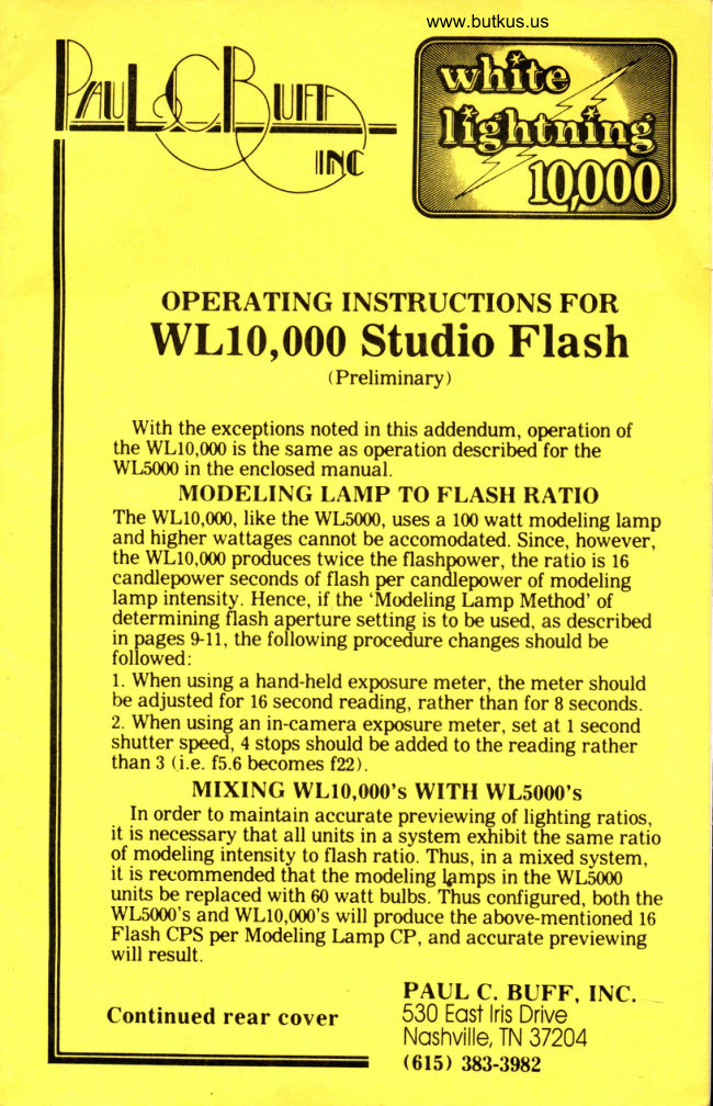
   OPERATING INSTRUCTIONS FOR
  WLf0,000 Studio Flash
                        (Preliminary)

  . WLq! the exceptions-the    noted in this addendum, operation of
 the WL10,000 is   same as operation described'for the
 WL5000 in the enclosed manual.
    MODELING LAMP TO FLASH RATIO
 The WL10,000, like the WL5000, uses a 100 watt modeling lamp
 and_hlgher wat[ages cannot be accomodated. Since, hoiever,
 the WL10,000 produces twice the flashpower, the ratio is 16
 candlepower             seconds                          of                          flash                             per candlepower                                                     of modeling- lamp       intensity.              Hence,                       the'Modeling                                     if                            Lamp Method'of
 determining flash aperture setting is t-o be uied, as described
 i-n_pageq $ll, the following procedure changes should be
 followed:
 f . When using a hand-held exposure meter, the meter should
 be adjusted for 16 second reailing, rather than for g seconds.
 2. When using an in-camera exposure meter, set at I second
 shutter speed, 4. stops should be added to the reading rather
 than 3 li.e. f5.6 becomes f22).
      MIXING WL10,000's WITH WL5000's
   In order to maintain accurate previewing of lighting ratios,
 it-is necessary that all units in a System exhibit ihe sime ratio
 of .modeling intensity to flash ratio. Thus, in a mixed system, it is recommended that the modeling lgmps in the WLS000
                        60 watt bulbslihus'configured, both the11TF be. replaced with
WL5000's and WL10,000's will produce the above--mentioned t6
 Fla.sh CPS per Modeling Lamf Cp, and accurate previewing
 will result.
                  PAUL C. BUFF. TNC.
Continued rear cover     530 Eo$ lris Drive
                                  Noshville, TN 37204
                             (615) 383-3982
View original page 1Page 3 · Read text
I        www.butkus.us
      SAFETY PRECAUTIONS
   All photoflash_equipment operates on high voltages which
 a-re potentially dangerous if proper safety precauti-ons are not
 observed. Internal capacitors can retain hlgh voltages even
 after unit is unplugged fronl the power source. untiained per-                                I
sons should not attempt to dismantle or repair the unit. In-the
 g-ase^ of physical damag-e or malfunction, r-efer all servicing to
 the factory or to trained service personnel.
  Never operate the unit in wet locations such as near
bathtubs, swimming pools or outdoors in wet weather. Com-
mon sense should accompany all usage.
     CHANGING THE MODELING LAMP
  The WL5000 unit uses a standard 100 watt household lamp
for-modeltlrg-, Standard 'Inside Frost' lamps are to be preftir-
red over 'Soft White' types, for optimum light charact6ristics.
                                                   no[hile  it is permissible to substitute lower wattage lamps,higher wattage than 100W should be used.
   Should it become necessary to replace the modeling lamp,
the following safety precautions shoirld be observed fiist.
1. Unplug unit from AC power outlet. Place both power swit-
ches in the 'out' position.
2. wait at least 5 minutes for internal capacitors to discharge.
NOTE: Capacitors will not discharge  if either power switch
has been left 'in'.
3. Unscrew old lamp and replace with new lamp.
       CHANGING THE FLASHTUBE
  The ring-flashtube used has a typical life of from b0,000 to
100,000 flashes                !n 4ormal usage. Eicept in heavy commercialggaggr it is_unlikely that replacement will be necessary.
Qfrould replacement be required, the safety precautioris for
discharging the unit (abov-e) must be observed.
  Once the unit has been discharged and the modeling lamp
removed,              flashtube may be unplugged, and a repi-acem^ent          lhe
re-inserted. It is recommended that a tissue paper be used to
handle the tube, and that it be held by the metal clamp which
holds the center pin in place.
*MAKE CERTAIN THE UNIT IS FULLY DISCHARGED
AND UNPLUGGED BEFORE ATTEMPTING TO SERVICE
FLASHTUBE TO PREVENT SHOCK HAZARD.
 FUSE FAILURE FROM MODEL LAMP FAULT
   It is possible for the internal fuse to fail as the result of
modeling lamp failure, particularly after the unit has been
subjected to mechanical abuse. should unit fail to operate, the
modelingl?-p should be removed and tested in another lamp
fixture. If the modeling lamp is burned out, and substitution of
View original page 3Page 4 · Read text
Venmo @mike-butkus-camera  Ph. 2083
PayPal Name  Lynn@butkus.org      www.PayPal.me/lynnbutkus
View original page 4
Page 5 · Read text
2
                                                        to the wl.,b000 unit, a           p,l9y llpp does not restore operation           blown internal fuse should be suspected. (See section orser-
            vice by trained personnel for repiacement of inteinu rusej.
          FACTORY REPAIR POLICY
                    It is of utmost concern to qs that our products perform
           with tle precision to which they are capable. Oui standard
          procedure                        perform                                             fa-btory seivice which might be                            ry Ig                              ?qy           required, within five workiirg days of our receipt. shoilld
            service be required, we recomm-end you call foi shipping in-
rl           structions to assure correct current dddress. when stripp'ing
          equjpment for service, be sure to include a short aescriptio"n
            of the prollem as well as youl' narye, address and telefhone
          number. If unit is in warranty, incluile date and placebf
             qurc-h_qry. we will return the unit to you prepaid, by stan-
            dard. uqs shipping. rf an estimate ftir any- nbn-warianty           service is desired, please request same.
       TWO YEAR LIMITED WARRANTY
                     Cl BS"f, Inc. guaraltegs to repair- or replace, free of charge, any part
                t'ound"^.l3ulto be defective-due t9 faufty materials or wbrkmanship. fne p6rioA of war-
                        years from the dale of original customer purchase-. tr''oi service             t"lty ig.two
             under this warranty, the unit must be returned to paul c. gufr, inc pi"p"ia, ny
               the original purchaser or his agept, This warranty shall not apply to'uniis which
             have.been resold, rented, abused, broken or opeiated in a m-a^nrjer inconsistent
              with the instmctions stated herein. Thervarrairty shall not apply to Oamige in-
                     in shipment or to damages which resirlt from att^e'mpted ;;p""i, by           "ur.*unauthorized persons.
                Neither Paul C. Buff, Inc., nor its agents or representatives shall be liable for
               apy.injury, loss or damage, dq"gt or consequential, arising from the use of or in-
                  ab.tfi!V.-!o uqe- the npdugt. Before using,'the puichaser" shall Oetermine tfre
              trlQllitv  of the product for the intended purpos^e and shall usu*u  iri riils ana                  liabilities.
             The obligation of l"ql C. Buff, Inc. is limited to repair or replacement only,           and no other warranty is expressed or implied.
             INTENDED USAGE
                   Lightning b000 is primarily intended for indoor ap-                 -.\ryhit"
             plications. in s.till photography. Thd unit is not designed foi use
            in wet or hostile environmbnis.
          The flash section emits light at a color temperature of ap-
          proximately 5500 Degrees Kelvin, and is bala-nced for corrbct
           .elpgsure of "DAYLIGHT" t]pe color films as well as for all-          black and white films. The modeling lamp is intended for
          scene preview, focusing and aperture calculations rather than
            ulpglglq It emits_light in the color temperature range of            {gl
           2000 to 28O0 Degrees K, depending on power settings.
             since the instantaneous flash intensity is some 4000 times
           brighter than themodelin_g l"ryp, the color temperature oii-
          ferenee between flash andmodeting lamps is of no conse-
         quence to the color balance on the exposed film.
View original page 5Page 6 · Read text
www.butkus.us
                                3
  White Lightning 5000 is designed to be used singularly, in
multiple, or in conjunction with battery operated camera flash
units. Provisions have been made to mount umbrellas and
other accessories commonly used in the professional photo
studio. Units are designed to be mounted on standard studio
lightstands or boom assemblies.
          POWERING
  The unit should be operated only from a standard 120VAC
50/60H2 outlet. The unit is internally fused to 2A. This
relatively low current consumption allows for safe operation
with standard light gauge (.J&/D household extension cords.
Typically, up to seven units may be operated from a 15A
power feed.
  Where 120VAC power is not available, the unit should be
connected to suitable transformers. Operation from
transformerless power convertors not designed for use with
electronic equipment should not be attempted, as these
devices may cause damage to the unit.
          MOUNTING
  White Lightning 5000 is fitted with a two-way mounting
block to mate with standard 3/B to 5/8 inch lightstands. The
unit should always be securely mounted when in use, and
cords should be routed where they won't be tripped over.
Units should not be left on unattended. The built-in swivel
bracket allows for aiming the unit conveniently.
   OVERHEAT CONSIDERATIONS
 WHITE LIGHTNING500O  is designed to be used in typical
studio setups, with accessories such as umbrellas, soft boxes,
etc.. As with any studio flash system, there are two potential
causes of overheating and subsquent possible damage. They
are: Excess heat from the modeling lamp, and overheating
from firing in too rapid a sequence, over an extended time
period.
  While the unit may be fired as soon as recycled for 10 to 15
shots, approximately double the recycle time is appropriate
for more extended shooting. In all-day shooting sessions, such
as in school photography,  it is not recommended that the unit
be fired more often than once per 10 seconds at Full Power.
  Care should be taken to prevent modeling lamp heat frorh
building up in the electronics section. Conditions which can
result in this hazard are long term operation in face down
positions, or with restrictions to the airflow around the reflec-
tor. If the shooting situation demands long term operation
under these conditions, a lower wattage modeling lamp should
be installed (i.e. 60 watts), or the unit should be turned off
after 15 minutes or so of shooting and allowed to cool.
                                                        www.butkus.us
View original page 6Page 7 · Read text
4
     PRELIMINARY INSPECTION
   Before attempting to operate unit, inspect for any possible
 damage in shipment. If physical damag-e is noted, iti not at-
 tempt ope.-ration. contact the carrier ordealer from whom you
 received the product immediately. Read and observe all saie
 ty precautions and instructions in this manual.
 TESTING AND FAMILIARITY ROUTINE
  1. Plug unit into a standard 120vAC b0/60H2 ouilet. press in
  '7e Power' switch. After a few seconds, modeling lamp should
 come on somewhat dimmed. (When unit is first-operaled after
      periods gf non-_t1se, initial charging and recy,ile times will long
 be relatively long. charging times witt?ecrease-after a few
 minutes of operation).
   Test-flash by momentarily pressing 'Test/Frash' button.
 unit should flish and. produ'cd an auffinte 'd;p;. Mod;jirrE--
 h-p. should go out, ttlen return on about l'seicond rater,Tn- dicating unit has recycled.
 2. Leaving'L/s Power' switch in, press 'z/spower' switch in.
 thus selecting Full Power. Modbiing lamp should mo-menidrily
 go out, tlun return on_brighter, indicatin! charge to Full
 Power. Press 'Test/Flash-'. unit should flash. Modeling lamp
 qhould go out, then return on after about 3 seconds. (Tf,e
 length of recycle time is influenced by power                                                    line voltage. If                                                 -the your power is substantially lower than    standard P0VAC,
 recycle ti4e may be somewhat longer. Recycle times will
 also be 20% longer when unit is opeiated with i}Hz power).
 3-. Lgqvin9'2/s Power' switch in, release 'ye power' switch to
 tbe '9_UT' position, thus selecting z/sPower. Modeling lamp
 should dim slightly. Test-flash onee more. Modeling lamp ^                                                                                          ^ should go out, then return on in about 2 seconds
 4. Notice that the modeling                                Jaryp_ always serves as a positive
 indicator of flaFh"ang recycle. Whenever it is_on, unit is charg-
 ed to within r/zf of. selected power, and is ready to flash.
   REFLECTOR/MODELING LAMP
  The reflector has been carefully_ designed for versatility in
all strootin_g situations. As supplied, with 100 watt inside tiojt
modeling lgmp, the flash is slighfly diffused and uv filtered
by the modeling lamp and the iesutt is an excellent correla-
tion between flash an-d modeling patterns, as well as controll-
ed effective flash souree-size, ad il rehtes to specularity. It is
permissable to oqerate the unit without modeling lampl or
with a clear-envelopg mo-deling lamp, without flIsh-pa^ttern
                                    i-ncrea-se in flash specularity.9gEf{gtign, but wilh ? glighj"soft      W!ri!e" type modeling lamps are not recommended-as
they will diminish the projected llash output to some extent.
View original page 7Page 8 · Read text
www.butkus.us

       BASIC US'
  Once you have made the initial                                       tests and become familiar             "*OCEDUREwith the unit, the following instructions are basic for its use. It
!s, however, recommended that you read this entire manual
for a full comprehension of the product.
1. Place the unit(s) as desired for the lighting effect you wish
to achieve. A darkened room is suggested solhat oniy light
from the modeling lamps illuminates the scene. This-wifl
allow an accurate visual preview of how the final exposure
will appear on film.
z., Adiu.st_ the individual power levels for pleasing light balance
if multiple units are being used.
3. Establish and verify the system sync, as described in "THE
SYNC LOOP'"
4.^ once you are satisfied with the positioning and power levels
of the units, as viewed through the camera,-determine the cor-
rect camera aperture, using either a flashmeter, a hand-held
exposure meter, or the internal exposure meter in your
camera. The section on "DETERMINING CORRECT EX-
POSURE" describes these methods in detail. If you have
chosen the "IN-CAMERA EXPOSURE METERT' method,
make sure you return the shutter speed to the setting recom-
mended for flash synchronization before actually shooting.
5. You are now_rg4y to begin shooting. Each time you shoot,
the brief period of darkness which follows seryes as a positive
indication that all units in the system did, indeed, flasli. When
all modelin-g lamps return on, you will have an equally
positive indication that the system is ready for anbther shot.
You may want to introduce a small amount of ambient light
from, say, a table lamp so there won't be total darkness i[ur-
ing the recycle period.
6. tf yoy are using WHITE LIGHTNING in eonjunction with a
portable        4?sh u4i! no! having a modeling lamp, keep in mind
that the effect of this light source will not be seen in the
vigwfinder, apd cgmposition must be made by estimating the
additional light effect caused by the portable flash.
7: If..you mix WHITE LIGHTNING with other professional
flash systems hayiqg modeling lamps, you must remember
that it is improbable these units will exhibit the same exacting
ratio of modeling illumination to flash intensity as does
WHITE LIGHTNING. In many professional studio flash
systems, the ratio of modeling vs flash intensity is neither ac-
cur-ate nor specified, and may vary from version to version
within a manufacturer's  line, or with various configurations of
porver supplies and flash-heads. Thus, in mixed systems, it is
folly to expe_ct the modeling illumination to provide an exact
preview of the illumination which actually exposes the film. It
View original page 8Page 9 · Read text
6
                is further not possible to accurately determine eorrect aper-
t            tureOnesettingsof the advantageswithout a flashmeter.of using an all WHITE LIGHTNING
           system is the confidence that what is seen in the viewfinder
            during modeling is an accurate representation of the picture
           whieh will appear on film. An additional advantage is the
               ability to use conventional exposure meters (when shooting in
            environments having suitably low levels of ambient light).
        LIFE EXPECTANCY OF MODELING
           LAMP AND FLASHTUBE
             While the modeling lamp will normally serve for around
            1000 hours before burnout, it will become slightly dimmer with
           use due to internal blackening. For optimum pelformance,  it
               is recommended this bulb be changeii after each 200 to 800
           hours of use.
           The ring flashtube has a life expectancy of from b0,000 to
             1001000 flashes, and should be replaced only with a direct
            r_eplacement available from the factory. In normal service,
            there is little likelihood of a need for replacement. Read and
           observe the safety precautions in this manual before replacing
            either lamp.
                                                                                  www.butkus.us            POWER SWITCHES
           The two switches marked "Vs" and "z/s' ' Power are used to
           turn the unit on or off, as well as to select flash power and                                                         ('off"            tracking modeling lamp intensity. The       cohdition results
         when both switches are "out". For safety in servicing, the in-
            ternal capacitors are discharged when the "Off" moile is
              selec.ted. C-omplete discharge of these capacitors requires ap
           proximately 3 minutes.
              TEST/FLASH SWITCH
             This momentary action switch serves to test-flash the unit.
                         units are connected by hard-wired sync cords, the          { mulliple        TEST/FLASH switch will only affect the unit tested. If hard-
           wired qyng is no! use{, all unils in a system will normally
             flash via the built-in slave trippers whenever any one unit is
             tested.          .             ITMBRELLA HOLDER
             This tube runs through the reflector in such a manner as to
           allow attachment of umbrellas or other accessories in the op-         tlmum position near the axis of illumination. Shafts up to yi'
          diameter may be inserted in this tube, and secured uslng the
          handnut on the top surface of the unit. Thus fastened, um-
            brellas will maintain their axial relationship to the light as ad-
           justments are made using the swivel mounting bracliet. Once
            positioned, the light unit may be secured by tightening the two
           swivel bracket handnuts on either side of the unit.
View original page 9Page 10 · Read text
www.butkus.us
                                    7
           SYNC JACK
  The eamera sync jack located on the rear panel of the unit
serves to hard-wire the unit to the camera shutter, using sync
cord supplied. In a multiple unit setup, at least one of the units
must be thus connected to the camera, unless the system is
triggered in a fully wireless fashion using a small portable
flash mounted on the camera. In all cases, the camera should
be set on "X" sync for electronic flash.
  The sync jack is extremely sensitive, and causes triggering
with only 20uA of current flowing through the camera con-                    I
tacts. It is isolated to produce no more than 50uA of leakage
cument to the AC powerline, for operator safety. The jack is a            Istandard 3 conductor audio phone jack. A standard mating
plug is available at most audio or electronics supply houses.
The circuit is arranged such that the positive terminal ap
pears at the jack "Tip", while the negative terminal is at the.
"Ring". The jack "Sleeve" is connected to the unit case.
  Multiple units may be wired to a common sync line by con-
necting all "Tips" together and all "Rings" together. It may
be necessary to selectively reverse the individual power cord
orientaions to secure reliable tripping in a hard-wired system.
Wrong or reversed connections to the sync jack circuit cannot
cause any damage to the unit.
  POWER LEVELS/RECYCLE TIMES
For the three selectable flashpower settings, the unit produces
130ws, 86ws and 43ws. It should be noted the WHITE
LIGHTNING 5000 is highly efficient in converting electrical
power to light energy. For the three flashpowers, the unit pro
duces 5000BCPS, 3200BCPS and 1600BCPS. The unit includes
electronie voltage regulation which assures constant flash
power at all power line voltages from 112 to 130VAC, and
which safeguards against damage from overcharging on ex-
cessively high line voltages. The modeling lamp system
automatically tracks the selected flashpower, thus maintain-
ing an exacting ratio of flash power vs modeling intensity.                 I
Specifically, when operated at 120VAC with the recommended100 Watt modeling lamp, one BCP of modeling intensity is pro-         l
duced for each 8 BCPS of flash power. This precise ratio,
together with careful correlation of flash and model coverage
angles assures that the scene previewed during modeling is an
essential replica of that which will be exposed with flash. In
terms of "f" values relative to Full Power, the "z/s" setting
produces approximately  -Vzf , while the "r/r" setting produces
about -lL/zf.
  The typical reeycle rates , to -Ysf of seleeted power are 3
seconds, 2 seconds and 1 second, for the three power settings.
These rates will be somewhat longer if your power line pro-
duces significantly less than the standard 120VAC, and will be
somewhat longer if the unit is operated at50HZ power.
View original page 10Page 11 · Read text
8
            BUILT-SLAVE TRIPPER
          The unit contains a built-in flash-sensitive slave tripper,
          loeated behind a small hole in the reflector. Because of its
           position, the tripper always "looks" in the same direction in
         which the unit is aimed. In most studio setups, sufficient flash
           illumination from other units will be bounced from the subject
          area, even with umbrellas in place, to cause reliable tripping.
            In difficult situations where very little light is reflected from
         the set to a unit, reliable tripping may require our accessoryI       RST1 Remote Slave Tripper, which plugs into the rear sync
         jack and which may be extended to any remote location using)         standard stereo earphone extension cords.
          The built-in slave tripper is automatically disabled
        whenever anything is plugged into the rear sync jack. Thus,
        when hard-wired sync is used, the flash from other flash units
           will not fire the WHITE LIGHTNING setup.
Mike Butkus                       Digitally                                                                DN:email=mike@butkus.org,Date:cn=Mike2023.02.20signedButkus,by20:34:36Mikeo=ButkusButkusc=US-05'00'camera manuals, ou=butkus.org,  SYNC CORDS
           Sync cords are shipped with each WL5000 unit. The_large
           diaineter plug shoulti be inserted in the rear Sync iaqk of the
            unit, while the small "PC" type connector mates with stan-
         dard camera sync terminals. A few newer 35mm cameras do
          not have a standard sync terminal, but are provided only with
        a "hot shoe" for on-camera flash units. Should your camera
         be of this type, it will be necessary for you to obtain a "Hot
         Shoe to PC Adaptor", available a most camera stores.
                 If your uhit is supplied with a two piece sync cord set, the
          longer cord will have a household "AC" type receptical while                                      ((AC"          the shorter cord will have an      two prong plug. If this is
          the case, sync polarity may be reversed by reorientating the
       AC male/AC Female pair. Certain flashmeters may operate
          with only one orientation, and it is possible that reversed
          polarity-may cause false tripping when the camera body is
           toucheil with metal objects. Should this be the case, simply
 I         reverse the orientation of the ACIAC pair.
I           Since the AC type sync connection method, while common        among professional flash systems, is compatable with
          household power outlets, caution is advised to prevent in-
          advertant insertion of AC type sync cords into household
            outlets. In particular, do not leave your camera around with
          the AC end of the sync cord exposed, especially around
           children, as a severe shock hazard and camera damage
           potential will then be present.
View original page 11Page 12 · Read text
www.butkus.us
                                   I
   EXPANDED USE INSTRUCTIONS
           SETTING UP
  Once the parameters and controls are understood, using
WHITE LIGHTNING is simple and straightforward. The
unit(s) should be plugged in and placed at positions and with
accessories which yield the desired illumination patterns,
while the power settings should be adjusted for pleasing light
ratios. If the modeling lamps are to provide an accurate
preview of the illumination, it is important that extran@us
ambient light be removed by darkening the room such that
only light from the modeling lamps illuminates the scene.
        THE SYNC LOOP
  Once the lights are positioned and adjusted, the SYNC
LOOP must be established. While in most setups the flash
from any one unit will trigger a flash in all other units via the
built-in slave trippers, some sort of electronic flash must be
triggered by direct wire to the camera to initiate the process.
  Usually, one of the WHITE LIGHTNING units will be wired
to the camera using sync cords provided, thus serving as a
"MASTER", from which other units will trigger. In a multiple
light setup, the following procedure is recommended in deter-
mining which unit is best positioned to serve as the' MASTER:
  With the units positioned as desired, press the TEST button
on the unit most conveniently located to the camera. It is pro-
bable that all units in the system will then fire, as verified by
the momentary absence of any modeling lamp, and that unit
may be used as the MASTER. Should this fail to fire all units,
selectively press TEST on each other unit, designating any
other unit which will fire all other units as MASTER. In short,
any unit which will cause all other units to fire is suitable to
be connected to the camera with a sync cord.
Remember . . . once a sync cord is connected to a unit, its
built-in slave tripper is disabled, and it will not fire except by
activating the camera shutter, or by momentarily shorting the
sync cord terminals at the camera end of the sync cord.
  Should a unit not fire from its slave tripper due to a location
receiving insufficient light from other units, the accessory
RSTI slave tripper may be plugged into the sync jack of that
unit to increase its slave sensitivity.
 TRIGGERING FROM CAMERA FLASH
  In some cases, it might be desirable to trigger the system
from a small battery operated camera flash. When this
method is used, it must be remembered that the camera flash
does not have a modeling lamp and may contribute scene il-
lumination not seen in the viewfinder. By using a low power -setting on the camera flash and bouncing it off the ceiling, its
effect on the exposure can be made minimal.
View original page 12Page 13 · Read text
l0
           At times., the photographer may wish to use a portable flash
          aq.? significant source of scene illumination, in cbnjunetion
         with one or more WHITE LIGHTNING units. Again, it is
        paramount to remember that the lack of modeling lamp will
                to negate         Lqnd                         lbe capability to visually preview t1e scrine.         Thus, it is usually wiSe to uie the wHlin IIcHTNING as the
        main source of light, yith the portable flash being used as a
         bounce or umbrella  fill. In this sort of use, the hgTrt ratios will
7       have to be estimated and some experimentation-will be in
          order.
     DETERMINING CORRECT EXPOSURE
            Professional flash systems such as wHITE LIGHTNING
         are inherently manual; requiring the photographer to deter-
          mine_an_d. preset the proper camera aiertur-e ahd shutter
               with respect to shutter speed, is long as the shutter is         lpgeo.
           fully open during the duration oi the.flash rtlooo to 1/1000 se-
         cond) the use of slower shutter speeds will not add to the ex-
         posure from flash illumination. However, slower shutter
         speeds will begin to allow unwanted ambient light to add to
         the exposure. Thus, the shutter speed should ne neta to that
       minimum which is consistent with the shutter being fully open
         dyriry the duration of the flash. In cameras using i-eraf tvpri
          shutters, speeds of r/250 are generally ideal. In cEmerai ^wittr
          focal plane, o-r "sliding" shutters, sodrewhat longer shutter
        speeds mupt be used, as these shutters are not rtlty open dur-
         ing the entire                                   period. Essentially all Bbmhr Sln                       _exposure
        cameras.employ focal plane shutters, and the correct speed
          for flash is normally engraved in red on the exposure tilme
           dial. Most sLR cameras are optimized for flash sync at r/60
         second, while certain newer mbdels allow sync ait/tzs se-
         cond. In all cases, if there is a choice, "X" iync should be us-
        ed with all electronic flash units.
        Aperture Determination . . . Flashmeter Method
         The most direct method of determining correct camera
         aperture.is by.use of a flashmeter. The speed of the film being
        used is dialed into such a meter and a teSt flash is made. The
        meter reads the total flash illumination falling on the subject,
                       the number or type of flash units used, and "         lggardless -of          diiectly indicates tlrq appropriate aperture to whictr the
       camera lens should be set. When pfrchasing a flashmeter, the
         user is cautioned to specify one which integiates the total   '
          flash illuminattgn,.as-oppoged                                         !o cheaper riodels whieh simply
        measure peak {l$h intensity. Furlhef, the user should verify-         the accuracy of the flashmeter with test shots. It should be
         noted that many commercially flashmeters are calibrated to
        underread by as much as one f stop, leading to overexposure.
View original page 13Page 14 · Read text
www.butkus.us
                                   11
 It isgen_erally eonceded that some amount of overexposure
can be desireable on negative type films, as it adds t-o color
satwation and shadow detail. Conversely, overexposure of
positive transparency film can be disasterous, leading to poor
contrast and washed out highlights. Hence, a rule of thumb:
Tend toward overexposure on negative film, and toward
underexposure on transparency films.
             Guide Number Method
  The Guide Numbers printed on the back of WHITE
LIGHTNING have been derived by exposure and lab testing
of professional transparency films. Guide Numbers were
devised to allow setting the camera aperture without meter-
ing, when a flash unit is used directly  . . . without diffusion, in
relatively small rooms with light colored walls and ceilings.
When larger, or darker environs are used, slightly lower aper-
ture settings than those indicated by the Guide Number
calculation  ( Ys to % stop) should be used. To use the Guide
Number method on a single WHITE LIGHTNING used direct-
ly, measure the distance from the subject to the center of the
unit, in feet. Refer to the GN chart on the unit, under the col-
qmn listing the ASA/ISO film speed you are using, and under
the power you have selected. Divide the indicaterl Guide
Number by the number of feet from light to subject, and set
the camera aperture to the result. EXAMPLE: If ASA100 film
were being used and the WHITE LIGHTNING 5000 were set to
Full Power, a GN of 160 would be found on the chart. If the
                                                      1G0 by 10,light were 10 feet from the subject, you would divide
for a correct aperture of f16.
   If umbrellas, diffusers, bounce techniques or multiple units
are being used, the Guide Number method can only serve as
an approximation of correct exposure apertures. It is typical
to expect a loss of from 1 to 2 f stops from diffusion techni
ques. When bounce lighting is being used, it is important to
measure the total light travel . . . from light to bounce surface
to subject. When multiple light sources are being used, it is
difficult to calculate how the light will "add". Inall of these
cases, you_should bracket the exposures over a2or 3 f stop
range, and make notes for future projects.
             Modeling lamp method
  The degree of success using this method depends upon the
accuracy of tne hght system.-If a known and accurate ratio of
modelin! tamp infensity vs flash power exists, together yith
well corielate-tl polar patterns from the two sources, flash
aperture deterniinatirin may be arqived- at by simply measur-
irig the illumination from the modeling lamp(s),upiug ? gon-
veitional hand-held exposure meter or the meter built into the
camera.
View original page 14Page 15 · Read text
t2
            Most studio flash systems do not exhibit the criteria
           necessary for such a measurement. WHITE LIGHTNING,
           however, has been specifically designed to accomodate this
          measurement technique, yielding accuracies comparable to
            those obtained with quality flashmeters.
          When the recommended 100 watt modeling lamp is used,
        WHITE LIGHTNING 5000 yields a constant ratio of 8 flash
          Candlepower Seconds for each modeling lamp Candlepower,
           accurate to r/zf at all power settings and under all conditions
             of use including when umbrellas, diffusers and bounce techni-
           ques are employed.
           The primary requirement for making accurate measure-
          ments by this method is to ascertain that the scene illumina-
             tion being measured is, indeed, coming from the modeling
           lamps, and not from error sources such as sunlight leakage or
          ambient room light. If there is doubt regarding the level of er-
            ror illumination, it is recommended that a first reading be
           taken with the modeling lamps off ; to determine the level of
          ambient light, and a second reading be taken with modeling
          lamps on. As long as the difference between the two measure-
          ments exceeds 3 f stops, you can be confident that error light
              will not significantly degrade the accuracy of the reading.
              USING A HAND-HELD EXPOSURE METER:
               1. With a hand-held exposure meter, take a reading from the
            subject position in exactly the manner as you would if you
          were planning to expose from the incandescent modeling
          lamps alone.
              2. Adjust the exposure meter to the film speed used, and for
          an exposure time of 8 seconds. Read the indicated aperture
              settirig directly from the exposure meter. This is the correct
             setting for your camera lens.
              3. The camera shutter speed should not be set for 8 seconds,
            rather, it should be set for flash exposure speeds (i.e. 1/60 se-
            cond), and its meter and film speed dial can be ignored.
              a. If filters are used on the camera lens, their light attenuation
          must be manually compensated for, as they would be with
          any other external metering method.
             USING THE IN.CAMERA EXPOSURE METER:
              1. Set film speed dial to correspond to film being used.
              2. Set shutter speed to 1 SECOND, compose and focus.
              3. Turn aperture ring for correct exposure indication on
         camera meter. Notate this aperture setting, then add 3 full
           stops (i.e. f5.6 becomes fr6). This is the correct aperture set-
             ting for actual flash exposure.
              4. Make absolutely certain that you return the camera to flash
           sync speed (i.e. f/60 second) before you actually shoot with
              flash.
              5. Using this method will automatically compensate for anyllrl             filters used, as well as for bellows compensation on close ups.

rl
View original page 15Page 16 · Read text
www.butkus.us
                               r3
    It is wise to develope an instinct for what approximate aper-
 ture should result from light setups regardless of the meteiing
 method chosen. For example, using ASA100 film, exposures
made in portrait/fashion type setups using umbrellas should
 genera-lly rest4t in apertures in the general range of f8 to f22,
depending on light distances and number. More specifically,
yoq should expect around an fll aperture from a single unit
with umbrella placed 5 or 6 feet from the subject, atFull
Power.
  INTERNAL FUSE REPLACEMENT
  The unit contains an internal 2A fuse which is not subject
 to failure unless an electrical fault is present. It is possible,
howeve{, for this fuse to fail as a result of modeling lamp
failure. In particular, severe mechanical shock, such as-
dropping the unit can cause a filament short in the model-
ing lamp which in turn can cause fuse failure.
  Should the unit become completely non-functional,  it is
recommended the modeling lamp be removed (Observing
the safety precautions in this manual) and tested in another
                               a burned-out modelingl"*p fixture. If such a test revealslamp, and the installation of a new lamp does not restore-
operation to the WLb000 unit, internal fuse failure should be
suspected. In this event, the unit may be taken to any
qualified electronics service person, along with this section
of the manual, for simple replacement of the fuse, as
follows:
 FOR QUALIFIED TECHNICIANS ONLY
DISASSEMBLY  . . . Before attempting to disassemble the
unit, the internal capacitors must be discharged according
to the instructions contained in this manual. Failure to do so
may result in the retention of dangerous voltages (315VDC),
and a shock hazard may be present.
  Once the unit has been discharged, the metal nut securing
the rear "Sync" jack should be removed. The entire elec-
tronics assbmbly may then be slid forward out of the ease.
The internal fuse will be located within a "twist-apart" type
holder, and should be replaced with an AGC2 type 2A, 2b0V
fuse. The electronics assembly should be return-ed to the
case before testing. In reassembling, power cord slack
should be taken up by pulling out on the power cord as the
electronics assembly is slid in. The umbiella support tube
must be properly located in the reflector and internal wir-
ing should be dressed to avoid pinching. Before securing the
sy-nc j?ck nut, the reflector may be rotated as necessary to
allow free operation of the rear switches.
  Should replacement of the fuse fail to restore normal
operation, the unit should be returned to the factory for ser-
vlcmg.
View original page 16Page 18 · Read text
www.butkus.us                                                                               .:i
                                                                                                                                                                                                                                                                                                                                 '
    SAFE OPERATING RECYCLE RATES                                        ;';q
    It is safe to continuously fire the WL10,000 as soon as it               .,{3 recycles for periods up to one minute (i.e. 20 consecutive
 flashes at Full Pwr, 30 at 2/3 Pwr, or 60 at l/S Pwr. For ex-
 tgnd$ sh-ooting_,    is recommended that triple the recycle                            -it time be allowed between shots to prevent potential dainage
 from overheating. Thus, 9 secondS at Full;6 seconds at zit
 and 3 seconds at l/3 would be indicated for long sessions.
    It should be noted that refinements have been made in the
 WL-1q,000      respect to its ability to withstand heavy usage,            -with                                                   - and that the stated                         !af,e operating rates are on a par wittr
 those of non-fan-cooled equipment from other manufacturers                                                                                                                                                                                                                                            ' {i of considerably heavier and more expensive equipment.
           FLASH DURATIONS                                                             .,,i
  The flash durations of the wL10,000 are aDproximatelv                                                     I
 twice those of the wl,s000.  . . t/3m sec at Fuiipwr, 1/b0dat                                     j
 2/3, and 1/s00 at t/3. These longer durations are conceded to              I
                               most professionals. Ii                        IIF                 to color fidelily by should"9y?ntageousbe noted, however, that the output bf electronic flash                   { follows an                     curve and that irormal specifications of     4           ^exponential flash duration indicate the time during which the initial6z% of the fl.ash energy is developed The reriaining 33% is
 gey.epped oyeT a longer-period of time. Thus, particularly at
 Full Power,  it is advi-sed-that shutter speeds idster than itm
 second.mqy gaus_e some slight loss of exposure. Tests shouid
 be conducted to determine optimum shutter speeds for your
 camera equipment.
     REAR PANEL CIRCUIT BREAKER
 _-The wL10,000 uses a circuit breaker instead of internal fuse.
 TF.rt, all notations in the manual which refer to repiac"-int of internal fuse               Qpplv to the rear panel button mar'tieo
 "RESET". should-the unit fail to operate, perhapi oue to
          t""^fpltrygq..as described in p"bq t, a momentary 11{gtt"g pressing of the RESET button will resetihe breaker. If this
                                                                                                                                                                               Idoes not restore operation, a fault exists which should be                                                                                                                                                                                                                                                                                                                                                               Ireferred to the faCtory for repair.                                                                                                                                                                                            ,'{{J
        SPECIFICATION CHANGESPOWERING    ....120vAC,50/6oHZ,l.5AWEIGHT...       ....3 pounds Total -FLASHTUBE. .                              . 2S0WS plug-in ringflash
                                                        . .2s,000 to 50",0ffi ftaihes typicalFLASHTUBE !l{EPowER suPPLy   ...zs0ws, Votiage-regulatddBCPS                    10,000, 6400, 3100
GUIDE NUMBERS.. 220, I85, I3O (ISO IOO)
FLASH DURATION.  l/300, l/500, l/800 second                                                                      {
  Add one r stop ,"                    Number nora-tions. Polar res-ponse"ff*f*;I:"-.",lldepatterns remain the same
View original page 18From the M. Butkus archive. Original publisher and archive notices are retained.
Check the model and edition against your equipment.
PDF verified 2026-10-10.