All 4 available source parts are included below.
Part 1
THE NEEDLEBAR Archive at ISMACS International
ONLINE MANUALS SECTION
INSTRUCTION BOOK
THE
ELDREDGE TWO SPOOL
(R. K. HOHMANN PATENTS)
SEWING MACHINE

WITH AUTOMATIC TENSION
Manufactured by
National Sewing Machine Company
BELVIDERE, ILLINOIS, U. S. A.
Transcribed for the NeedleBar by Helen Scarth
Part One
INDEX
|
Page
|
|
|
Automatic Tension............................................................................................
|
10
|
|
Belt......................................................................................................................
|
15
|
|
Breaking the Lower Thread.............................................................................
|
15
|
|
Breaking the Upper Thread.............................................................................
|
15
|
|
Changing the Self Setting Needle...................................................................
|
14
|
|
Cleaning the Machine.......................................................................................
|
9
|
|
Commence Sewing..........................................................................................
|
7
|
|
Drawing up Under Thread................................................................................
|
7
|
|
Embroidering.....................................................................................................
|
12
|
|
General Instructions..........................................................................................
|
1
|
|
Hook Mechanism..............................................................................................
|
13
|
|
Needles & Thread.............................................................................................
|
5
|
|
Oiling & Adjusting Stand..................................................................................
|
16
|
|
Oiling Machine...................................................................................................
|
2-4
|
|
Presser Foot......................................................................................................
|
14
|
|
Price List of Attachments.................................................................................
|
18
|
|
Price List of Parts.............................................................................................
|
19-22
|
|
Price List of Stand Parts..................................................................................
|
17
|
|
Raising or Lowering Feed...............................................................................
|
13
|
|
Regulating Stitch...............................................................................................
|
10
|
|
Removing Spool Case.....................................................................................
|
8
|
|
Removing Work.................................................................................................
|
15
|
|
Replacing Spool Case.....................................................................................
|
9
|
|
Sewing Guide....................................................................................................
|
14
|
|
Skipped Stitches..............................................................................................
|
15
|
|
Spool Case Locking Device............................................................................
|
8
|
|
Threading Machine...........................................................................................
|
6
|
|
Threading Spool Case.....................................................................................
|
8
|
| Under View of Machine.................................................................................... |
4
|
| Warranty............................................................................................................. |
18
|
| Winding Spools................................................................................................. |
11
|
GENERAL INSTRUCTIONS
Before leaving the factory, this machine has been carefully adjusted and minutely inspected, its sewing qualities having been tested on all kinds of work, and found perfect in every respect.
This machine runs toward you, do not run it backward under any circumstances.
Before commencing to sew, be certain to oil and clean machine according to instructions on pages two, three, four and nine.
After using the machine, always see that it is well cleaned before putting it away.
Do not tamper with the adjustments of the machine; serious trouble is almost sure to result from any unnecessary meddling with the working parts.
Do not attempt to use the attachments until you can manage the machine with ease on plain sewing.
In sewing, where special elasticity is required, as on bias seams or very elastic material , hold the work back slightly to keep the cloth stretched while being sewed.
The belt should be only tight enough to move the machine without slipping. If it is too tight, it will make the machine run hard. Should it become too loose, a piece must be cut out near the belt hook and another hole made and hooked again.
Machine not working properly is generally caused by the following: -
The thread too coarse or fine for the needle; the needle bent or blunted; poor thread. See that the needle is perfectly straight and that it is pushed up as far as it will go into the needle bar. When properly set, it should pass through the needle plate hole a trifle to the right of the center.
Should the machine skip stitches in running off a thick seam, hold the cloth back slightly to keep it straight and to prevent its raising up with the needle. If slackly twisted or uneven silk is used and becomes frayed or roughened, the needle is too fine or has a hook upon its point, caused by striking the needle plate.
To turn a corner. Stop the machine with the needle in the cloth, after it has been down and comes partly up. Then lift the presser foot and turn the work in the direction desired, using the needle as a pivot.
The presser foot must never be left down on the feed when the machine is running, unless there is cloth between, as the sharp teeth of the feed will injure the bottom of the presser foot.
When ordering needles or parts, or supplies of any kind for this machine, always give dull name and number of the machine. This number will be found stamped on bed plate to the left of the stitch regulator.
Use only needles stamped ELDREDGE TWO SPOOL.
OILING THE MACHINE
(Continued on pages 3 and 4)
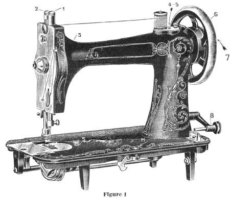
OIL EACH BEARING AS INDICATED BY A NUMBER
See that the needle bar is at highest point, then turn hand wheel toward you slowly and as the needle bar descends, stop machine when the eye of the needle is even with the top of the needle plate. Keep the machine stationary in this position and oil bearings indicated by numbers (1) to (8) inclusive. No. 1 indicates place to oil needle bar through top of cap; No. 3, left-hand bearing of top shaft; No. 4, crank connection bearing; No. 5, tube carrying oil to the connection slide block.
The Bearings, numbers (4) and (5) are oiled, as you will observe, through an oil hole in the spool pin plate. (Remove the knurled thumb nut holding this plate in place; swing it aside and you will then see the necessity of oiling bearings as indicated by these numbers (4) and (5). After becoming familiar with the location of these two oiling places, it will not be necessary to swing the plate back to oil them.) No. 6 is right-hand bearing of main shaft; No. 7, loose pulley wheel; No. 8, spool winder bearing.
|
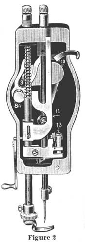
OILING THE FACE PLATE PARTS (See figure 2) To oil face plate parts, it is necessary to remove the steel face plate by removing the knurled thumb screw near the top of the plate, (See letter "B", figure 3). Turn hand wheel until needle bar is at highest point and oil parts indicated by number, as follows: - No. 8A - Take-up Bearing Stud. No. 9 - Take-up Roll Slot. No. 10 - Upper end of Needle Bar Driving Pitman. No. 11 - Lower end of Needle Bar Driving Pitman. No. 12 - Lower end of Needle Bar. No. 13 - Gib Pin Do not oil too liberally, or the oil will drip down and soil the goods. After oiling, wipe off all superfluous oil and replace face plate. OIL THE MACHINE EVERY DAY YOU USE IT. |
 |
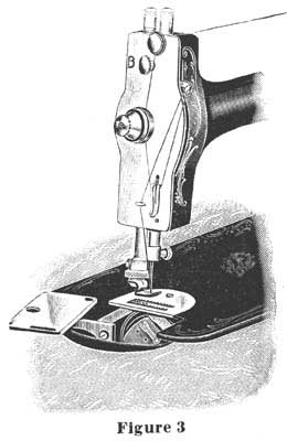 |
OILING THE HOOK RACE (See figure 3) The accompanying illustration shows the spool case cover open, to permit oiling of the hook race, full directions for same being given on the following page. After oiling these parts and before starting to sew, be sure that the Spool Case Cover is closed. If the Spool Case Cover works loose and will not stay tightly closed, insert screw driver in slot in cover, (See figure 3, this page) and expand the slot sufficiently to cause a tight fit. |
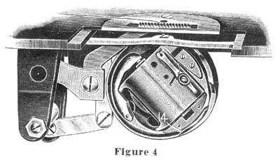 |
At the left is a large sized illustration of the Hook Race, showing clearly and in detail the various parts. Oil the Hook Race at point indicated by an arrow (number 14). A very few drops of oil will suffice. Oil the machine every day you use it. |
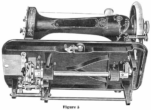
Figure 5
UNDER VIEW OF MACHINE
The above illustration is an under view of your machine. It shows the feed mechanism and the simplicity of construction, which cause the machine to run so easily and quietly. Oil all bearings indicated by the letter "O". To turn the machine back for convenient oiling from below, simply press down button operating the Automatic Head Latch, indicated by letter "M", (figure 1, page 2).
Part Two | Part Three | Part Four
Part 2
THE NEEDLEBAR Archive at ISMACS International
ONLINE MANUALS SECTION
INSTRUCTIONS FOR USING THE
ELDREDGE TWO SPOOL
SEWING MACHINE
Part Two
SIZE OF NEEDLES AND THREAD TO BE USED ON DIFFERENT MATERIALS
|
CLOTH
|
SIZE NOS. OF NEEDLES
|
THREADS
|
||
|
COTTON
|
SILK
|
LINEN
|
||
| Finest Light Weight Goods |
No. 00
|
200 to 500
|
000
|
-
|
| Fine Linens and Silks, Lawns and Nainsooks |
No. 0
|
100 to 200
|
000
|
-
|
| Collars, Handkerchiefs, Fine Shirts, Underclothing |
No. B
|
80 to 100
|
0 to 00
|
-
|
| Common Muslins, Light Clothing and Quilting |
No. 1/2
|
60 to 80
|
A to 0
|
-
|
| Tailoring, Light Clothing and Boys Clothing |
No. 1
|
40 to 60
|
A to B
|
90 to 100
|
| Heavy Dressmaking, Cloakmaking and Heavy Tailoring |
No. 2
|
30 to 40
|
B and C
|
70 to 80
|
| Extra Heavy Work |
No. 3
|
24 to 30
|
C and D
|
50 to 90
|
| For very coarse work only |
No. 4
|
-
|
-
|
-
|
Always use the same size of thread on lower spool as on upper one.
The number of the needle is marked upon its shank.
Note: - Scale showing proper needle to use with different sizes of thread is stamped on the spool case cover.
In ordering needles, they are for ELDREDGE TWO SPOOL MACHINE and give the sizes wanted. If you cannot possibly procure genuine needles marked ELDREDGE TWO SPOOL you can use regular Singer V.S. No. 2 needles.
THREADING THE MACHINE (See figure 6)
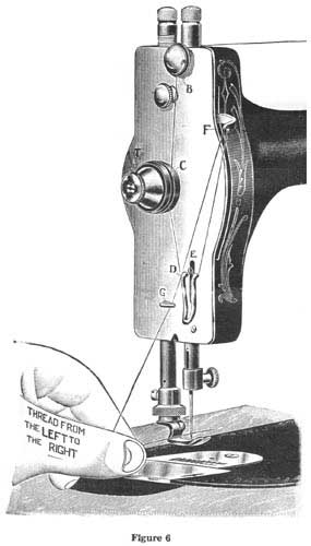
Before threading the machine, turn the hand wheel toward you until the take-up is at the highest point. Place spool of thread on the spool pin. Draw the thread from the spool under the hook and down between the discs "B", passing the thread on side toward you between the discs. Be careful not to wrap it around them. From point "B", carry the thread straight down and once around the tension pulley "C", then down under the auxiliary hook and spring "D & E". Then up through the take-up "F", (threading from the front) down through the thread guide "G". (There is an opening in the guide "G" at left side to allow thread to enter it.) Then through the eye of the needle, threading from left to right.
TO DRAW UP THE UNDER THREAD
(See figure 6)
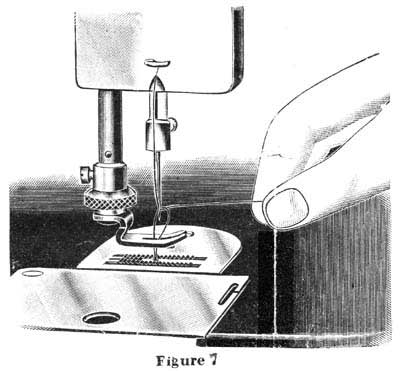 |
Let the thread extend through the needle two or three inches when the take-up is at its highest point. Now hold this end of the upper thread slackly with the left hand and turn the hand wheel carefully toward you while the needle goes down and raises again to position shown in figure 7 above, bringing the take-up again to its highest point. Then draw the upper thread and the under thread will come up with it, as shown in the illustration. Pass both threads under the presser foot, keeping your foot in the treadle to hold the take-up at its highest position. It is necessary to draw up the under thread before putting cloth under the presser foot and starting to sew, in order to make perfect stitches from the start. |
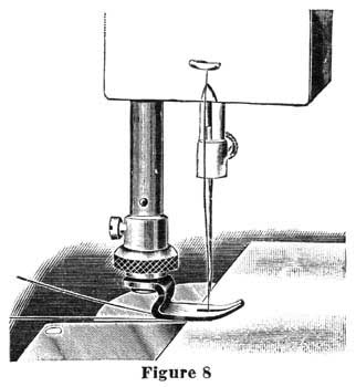
TO COMMENCE SEWING
(See figure 8)
|
Pass both threads under the foot at the back, as shown in illustration, placing the cloth under the presser foot and letting down the presser lifter, which lowers the foot onto the goods. Start the machine by turning the hand wheel toward you. Do not pull or push the work. The feed will carry it properly. START RIGHT When starting to sew, be sure that the threads and cloth are in position, as shown in this illustration. |
 |
REMOVING THE SPOOL CASE
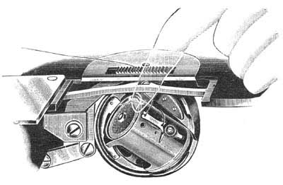 |
| To remove the spool case, open the spool case cover, as shown in figure 3, (page 3), and with the forefinger, as shown in figure 9, above, swing the top of the spool case outward and grasp it between the thumb and first two fingers, raising it upward out of the machine. Do not remove spool case when needle is down, as this may bend the needle. Be sure that the point of needle is above the needle plate. |
THREADING THE SPOOL CASE (See figure 10)
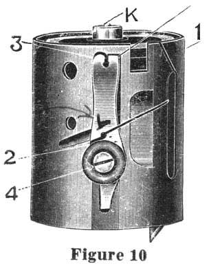 |
In threading the spool case, take it in the left hand, placing the spool on the spindle (see letter K, figure 10), then drawing the thread as indicated, into the slot (no. 1), over the case and under the tension spring (No. 2). Hold the thread with the thumb, against side of spool case at point between No. 2 and slot (No. 1) then draw it under the end of the tension spring (No. 3). Leave about two inches of thread projecting outside of the case. THE SPOOL CASE LOCK The Spool Case is locked in position in the stationary race by a spring plunger located in the top of the spool case spindle, (see letter K, figure 10). It is possible after long use this spring plunger may wear and fail to snap into place, or to hold the case firmly in proper position. This can be adjusted by pressing down upon the spring plunger with a screw driver, until the screw driver slips into the slot of the hollow screw surrounding the plunger. Then turn this hollow screw to the left about one quarter turn, possibly slightly more or less, depending on how the case fits. By turning this screw to the left, it will raise this spring plunger higher above the head of the spindle. |
INSERTING THE SPOOL CASE
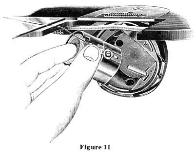 |
| Be sure that the needle bar is at its highest point before attempting to place spool case in position. Grasp the spool case between the thumb and first two fingers of the left hand, placing the thumb directly over the tension spring on spool case, as shown in the above illustration. Place the spool case on spindle, (see letter "L", figure 11) then push it down as far as it will go and press it inward with the finger until it locks into place. If it fails to lock, the case is not in the correct position to fit properly. By turning it slightly to the right or left, it can be pushed down so it will lock in proper position. |
TO THOROUGHLY CLEAN THE MACHINE
Granting that the machine has been kept thoroughly well oiled and clean, it may still occur, if the oil is poor or if the machine is allowed to stand a long time without using, that the oil may dry out of the bearings or get thick and gummy, which will cause the machine to run hard and may seriously injure the bearings. When a machine is in this condition, before applying fresh oil, it is well to apply kerosene to all of the bearings very liberally, meanwhile running the machine slowly by hand to move the working parts. Apply kerosene at intervals every few moments, until every bearing has been thoroughly flooded and all of the residue from dry or thick gummy oil, has been thoroughly dissolved and washed out. Then run the machine slowly a few minutes to allow the kerosene to work out of the bearings, after which, wipe the machine dry and free from all kerosene and apply fresh machine oil. By following these instructions carefully, the machine will always run light and free.
THE AUTOMATIC TENSION
The Automatic Tension is a most important feature of this machine, as it is entirely self-acting, requiring no attention or adjustment by the operator, regardless of the nature of the fabric or of the size or kind of thread used. This machine, before leaving the factory, is tested on a very wide range of thread and fabric and under all ordinary conditions of family sewing. Absolutely no adjustment of the tensions is required for this work.
If for manufacturing or special work of any kind, it is desirable to alter the tensions, the upper tension can be adjusted in the following manner: - Turn the knurled thumb piece on the tension disc "T", (figure 6, page 6) toward you to tighten the tension, or to the left, or from you, to decrease the tension.
Tension on the spool case can also be adjusted, but rarely, if ever, is this necessary. To change this tension, turn the screw No. 4 (figure 10), page 8) to the right to increase, or to the left to decrease tension.
When the tensions are properly adjusted the stitch should lock in center of goods thus:

When upper tension is too tight, the upper thread will lay flat on upper side of goods and stitch appear thus:
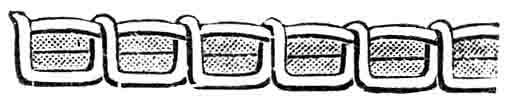
When upper tension is too loose, the lower thread will lay flat on under side of goods and stitch appear thus:

THE STITCH REGULATOR
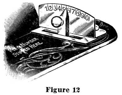
The numbers on the index plate from "1" to "0" indicate long and short stitches. By removing the stitch regulator from you to No. 1, the machine will sew five stitches to the inch, while at No. 0 it will sew thirty-five stitches to the inch. This is a wider range than on any other machine. You may sew any desired length stitch by moving this switch regulator to the point on scale to suit requirements. The regulator automatically locks itself at all points.
WINDING THREAD ON AN ORDINARY SPOOL
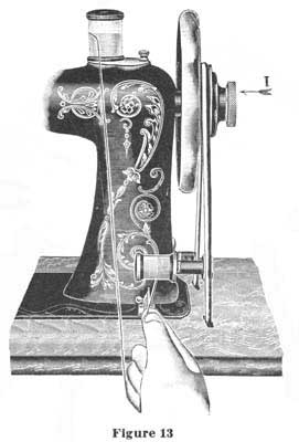
One of the principal features of this machine is the savings of winding bobbins as on other machines. It may happen that you will have only one spool or part of a spool of thread available. In that case, take an empty spool that will fit into the spool case (size 50 spool or smaller) and wind onto it by means of the Automatic Spool Winder, the quantity of thread you may desire to use. Before starting to wind thread, release the hand wheel, by turning the knurled thumb piece (letter "1", figure 13) one half turn toward you. This throws the machine out of gear. Then place full spool on spool pin, as illustrated. Next take the empty spool in the left hand and with the right hand, wrap a few strands of the thread around this spool. Then place spool on the spindle of the spool winder, using care that the thread runs the under side of the spool, as illustrated. Raise the spool winder until the pulley comes in contact with the belt, then start the treadle and proceed to wind spool. If you wish to sew with thread that is coarser than No. 50, you can easily do so by winding the same onto an empty No. 50 spool, following instructions as given above.
Part One | Part Three | Part Four
Part 3
THE NEEDLEBAR Archive at ISMACS International
ONLINE MANUALS SECTION
INSTRUCTIONS FOR USING THE
ELDREDGE TWO SPOOL
SEWING MACHINE
Part Three
INSTRUCTIONS FOR EMBROIDERING
Initial or pennant work may be made by using full sized wool zephyr yarn or three or four colors of darning cotton, in place of the lower thread, (upper thread äs usual). In order to do this work without changing either tension of the machine, we recommend winding the yarn on a No. 50 empty spool. Place this spool on the spool winder and wind the yarn on the spool in accordance with instructions on page 11. To thread the spool case with this zephyr yarn, take the case in the left hand and the spool in the right hand. Insert the end of the yarn outward from the inside of case through the slot, across the outside of case and over (not under) the tension spring, then downward from the outside of the case through the hole, and bring this end out again from the inside of the case through the hole, leaving about three inches of thread projecting that the upper thread can pick it up. (Important. Do not place spool in case until you have threaded case as above instructed.) Be sure that the yarn is on the outer side of tension spring. If there is any slack yarn, it should be wound up on the spool. Then put spool in case, using care to see that none of this yarn is wrapped around the spindle, in the center of the spool case, onto which the spool slips. You may now proceed to embroider, the same äs in doing regular sewing, setting the stitch regulator for any length stitch to suit the class of work desired. The letters or patterns should be stamped with a tracing wheel on the wrong side of the goods, which, in doing this work, is the upper side of the goods, the design in yarn appearing on the under side, as the machine operates.
The above instructions apply when using smaller yarns. When using heavier
yarns thread to No. 6 only, omitting No! l and No. 5.
TO RAISE OR LOWER THE FEED
 |
|
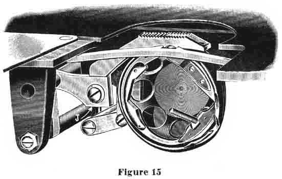
The feed is attached to feed bar by means of screw
"J" (figure 15). In order to raise or lower the feed, first
raise the presser foot so that it will stand free of the feed. When
loosen screw "J", which will allow the feed to be raised or
lowered as desired. To determine if feed is at proper height, turn hand
wheel until the take-up is at highest point. With the take-up standing
in this position, the feed points should protrude through the needle
plate just the length of these points.
|
THE HOOK POINT AND HOOK RACE
 |
|
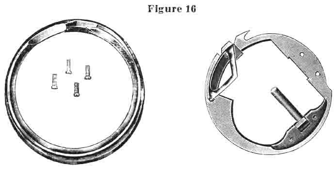
The above illustration shows the different parts of
the hook mechanism, not assembled. If the hook race is taken out of
the hook, be sure to wipe it clean and put a few drops of oil into it
before screwing on the hook plate to fasten the race in position.
|
TO CHANGE THE SELF-SETTING NEEDLE
TO REMOVE the needle, raise the needle bar to its highest point, loosen the needle clamp screw by a slight turn toward you and slip the needle down until it is free.
To set the needle, take it in the left hand, placing the point through the
hole in the needle plate and then pass the needle up into the bar. In doing
this, be sure that the needle is pushed up as far äs it will go and that
the long groove of the needle is on the left side and the short groove and
flattened shank are to the right.
THE PRESSER FOOT
THE pressure of the foot, as the machine is sent out from the factory, is correct for ordinary sewing, but can be graduated by the presser bar screw, (see No. 2, figure l, page 2) turning this presser bar screw to the right or downward, for more pressure, or to the left or upward for less pressure. The pressure on this foot, as the machine is sent out from the factory, will not need changing, even for very light work. It may be necessary to increase the pressure for extraordinarily heavy work. If the pressure is too heavy when sewing thin goods, the feed will cut the goods.
The presser foot must be set so that the needle passes midway between the two prongs. If the foot is set a little to one side or the other, it is likely to push the needle out of its proper place and make it strike the needle plate, thus blunting the needle or cutting the upper thread.
The presser foot is raised by means of the lever directly back of the face plate. This is called the presser bar lifter and is operated by raising it up to its full height until it slips into place. To lower the presser foot, reverse this action.
To remove the presser foot, raise the presser bar lifter and loosen the knurled hub nut which holds presser foot in place.
Avoid pushing and pulling the goods while stitching, particularly the latter.
This is usually the cause of broken needles, due to the fact that the operator
will grasp the goods after it has passed over the feed and pull it, with the
idea of aiding the feed. If the goods stretches or slips a little, it will
be apt to carry the needle with it, that is, bend it a trifle out of its proper
position, so that it will strike the needle plate and either bend or break.
Be particularly careful to avoid either pushing or pulling the goods, as the
feed will carry through any class of material without aid.
SEWING GUIDE
WITH each machine is furnished a Sewing Guide, together with thumb screw. This guide is fastened to the bed of the machine by means of the thumb screw, as indicated by letter "S", (figure l, page 2.)
REMOVING THE WORK
T O REMOVE the work, stop the machine with the needle out of the goods and
with the take-up lever at its very highest point. This is Important.
Raise the presser foot with the presser bar lifter, located at the back of
the face plate. As this is done, the Automatic Tension Release comes into
action and releases all tension on the upper thread. Next draw the work backward
away from the presser foot. Then bring both threads over from the back and
cut them with the blade of the thread cutter which fits into the presser bar.
THE BELT
THIS machine works best with as loose a belt äs can be used without
slipping on the belt wheels. If the belt is too loose, disconnect the coupling
and cut off a little from one end, say half an inch. The large drive wheel
on the stand has a close fitting wheel guard which holds the belt always in
position on this wheel. When you desire to turn the sewing head back for oiling
or cleaning, simply slip the belt off of the upper pulley on outside of hand
wheel.
SKIPPED STITCHES
THESE are sometimes caused by using a needle too small for the thread, using
a bent needle, or by the improper setting of the needle. In setting the needle,
the long groove must, be turned toward the left, the flat shank toward the
right and the needle must be pushed up into the needle bar äs far äs
it will go, and secured firmly by the needle clamp.
BREAKING THE UPPER THREAD
THIS may be caused by improper setting of the needle, using a needle with
a sharp or imperfect eye, the thread uneven or too large for the needle, the
upper tension too tight, or by improper threading of the machine. It is important
that the needle pass directly between the prongs of the presser foot and through
the hole in the needle plate, without rubbing. If the needle rubs against
the presser foot or the sides of the needle plate hole, there is danger of
breaking the upper thread.
BREAKING THE LOWER THREAD
THIS may be caused by having too much tension on the spool case or through the improper threading of this spool case. It is also possible if the end of thread from the spool case is allowed to be caught in the spool case cover, or if there is any slack thread in the spool case which may become wound around the spindle (letter "K", figure 10, page 8.)
TO OIL AND ADJUST THE STAND
 |
|
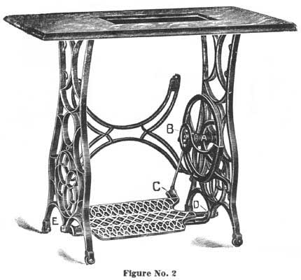
THE Stand should be oiled in five places. which are
indicated by the letters A, B, C, D and E on the above cut. "A"
marks the wheel stud bearing. ".B" marks the pitman stud bearing
at upper end. "C" marks the lower end of pitman. "D"
and "E" mark the treadle center screw bearing.
To adjust the belt wheel, loosen the lock nut at end of wheel stud on outer side of leg. With a large screw driver, turn the wheel stud to the left until the lost motion is taken up, then tighten the lock nut securely The adjustment should be made with the belt removed. To adjust the pitman, turn the small screw at the top of pitman head so the right until the lost motion is taken up, or if the lost motion is at the bottom at the treadle connection, loosen one of the nuts and turn the headless center screw to the right until the required adjustment is made, then tighten the lock nut securely. To adjust the treadle, loosen the lock nut on the outer side of leg at the bottom and turn the headless center screw to the right slightly, then the lock nut. |
Part One | Part Two | Part Four
Part 4
THE NEEDLEBAR Archive at ISMACS International
ONLINE MANUALS SECTION
INSTRUCTIONS FOR USING THE
ELDREDGE TWO SPOOL
SEWING MACHINE
Part Four
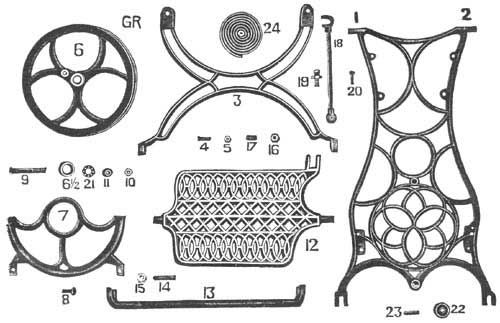 |
|||||
|
No.
|
Name |
Price
|
No.
|
Name |
Price
|
|
1
|
Right Leg |
$2.75
|
15
|
Treadle Center Screw Nut |
$ .10
|
|
2
|
Left Leg |
$2.75
|
16
|
Treadle Pitman Center Screw Nut |
.10
|
|
3
|
Brace |
1.25
|
17
|
Treadle Pitman Center Screw |
.10
|
|
4
|
Brace Bolt and Nut |
.10
|
18
|
Pitman complete |
.75
|
|
6
|
Wheel |
1.75
|
18½
|
Pitman Ball retainer with balls |
.20
|
|
6½
|
Wheel Cup |
.10
|
19
|
Pitman Ball Stud |
.15
|
|
7
|
Wheel Guard |
.70
|
20
|
Pitman Ball Stud Adj. Screw |
.10
|
|
8
|
Wheel Guard Screw |
.10
|
21
|
Ball Retainer complete with balls |
.10
|
|
9
|
Wheel Stud |
.25
|
22
|
Caster |
.10
|
|
10
|
Wheel Stud Nut |
.10
|
23
|
Caster Pin |
.05
|
|
11
|
Wheel Stud Cone |
.10
|
24
|
Belt |
.45
|
|
12
|
Treadle |
1.50
|
|||
|
13
|
Treadle Support |
.40
|
|||
|
14
|
Treadle Center Screw |
.10
|
|||
|
When ordering parts for the stand, always state
in the order they are for the Stand, and give name as well as the number
of the part wanted.
|
|||||
|
PRICE LIST
|
|
| Ruffler....................................................................................................................................................... |
$1.50
|
| Tucker....................................................................................................................................................... |
1.50
|
| Foot Hemmer Sets including Binder..................................................................................................... |
.75
|
| Braider Foot............................................................................................................................................ |
.25
|
| Thread Cutter........................................................................................................................................... |
.05
|
| Hemmer and Feller................................................................................................................................. |
.50
|
| Presser Foot........................................................................................................................................... |
.25
|
| Spool Case.............................................................................................................................................. |
1.50
|
| Needles all sizes, per dozen.................................................................................................................. |
.30
|
| Guide Thumb Screw............................................................................................................................... |
.25
|
| Oil Can..................................................................................................................................................... |
.15
|
| Screw Driver............................................................................................................................................ |
.15
|
| Shuttle Screw Driver............................................................................................................................... |
.10
|
| Quilter....................................................................................................................................................... |
.05
|
|
This machine is supplied with certificate of warranty, properly dated and signed, good for ten years from date and covering the breakage of parts that prove defective in any way. The warranty does not include attachments, needles or spool cases. Remember that every machine before leaving the factory is thoroughly tested on all kinds of work and that it must be right when received. Should there be anything about the machine which you do not understand, correspond or communicate with the manufacturer or your dealer before condemning it. In ordering needles, state they are for Eldredge Two Spool Machine and give size wanted. If you cannot procure genuine needles marked Eldredge Two Spool you can use regular Singer V.S. No. 2 needles. Always speak a good word for your machine whenever and wherever you can. |
|
|
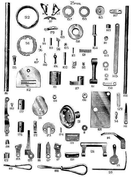
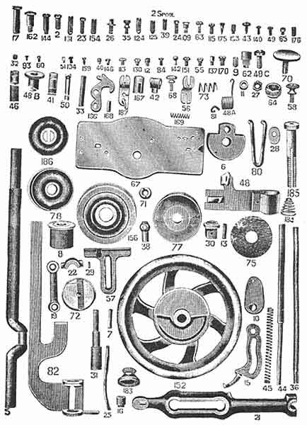
ILLUSTRATED PRICE LIST OF PARTS FOR THE ELDREDGE TWO SPOOL SEWING MACHINE WITH AUTOMATIC TENSION |
|||||
|
No.
|
Part | Price |
No.
|
Part | Price |
|
1
|
Arm (not illustrated) |
$5.00
|
43
|
Needle clamp screw |
.05
|
|
2
|
Arm post screw |
.05
|
44
|
Presser bar |
.35
|
|
3
|
Bed (not illustrated) |
5.00
|
45
|
Presser Bar Spring |
.10
|
|
4
|
Main Shaft Complete (includes Nos. 5,6 & 7) |
3.00
|
46
|
Presser Bar cap |
.10
|
|
5
|
Main Shaft |
1.50
|
47
|
Presser Bar gib complete |
.10
|
|
6
|
Main Shaft head |
.65
|
48
|
Presser Bar gib |
.10
|
|
7
|
Main Shaft head pin |
.05
|
48a
|
Auxiliary Tension Spring |
.05
|
|
8
|
Main Shaft bushing |
.65
|
48b
|
Auxiliary Tension Head |
.10
|
|
9
|
Main Shaft bushing set screw |
.05
|
48c
|
Auxiliary Tension Head screw |
.05
|
|
10
|
Take Up Crank |
.65
|
49
|
Presser Bar gib Clamp screw |
.05
|
|
11
|
Take Up Crank roll |
.15
|
50
|
Presser Bar gib guide wire |
.05
|
|
12
|
Take Up Crank roll stud |
.10
|
51
|
Presser Bar gib guide wire set screw |
.05
|
|
13
|
Take Up pin (2 used) |
.05
|
53
|
Presser Bar Lifter |
.10
|
|
14
|
Take Up complete |
.55
|
54
|
Presser Bar Lifter handle |
.10
|
|
15
|
Take Up lever |
.20
|
55
|
Presser Bar Lifter screw |
.05
|
|
16
|
Take Up hub |
.05
|
56
|
Presser Bar Foot |
.30
|
|
17
|
Take Up fulcrum stud |
.05
|
57
|
Cloth Guide |
.10
|
|
18
|
Take Up Fulcrum stud set screw (See No. 153) |
.05
|
59
|
Quilter |
.10
|
|
19
|
Needle Bar Link |
.20
|
60
|
Quilter screw |
.05
|
|
20
|
Main Shaft Conn. complete (includes No. 23-25) |
1.25
|
61
|
Attachment Holder complete (not illustrated) |
.50
|
|
21
|
Main Shaft Conn. |
1.00
|
62
|
Attachment Holder Hub |
.12
|
|
23
|
Main Shaft Conn. cap screw |
.05
|
63
|
Attachment Holder Hub Foot Screw |
.05
|
|
24
|
Main Shaft Conn. Cap hollow screw |
.05
|
64
|
Attachment Holder Hub Nut |
.10
|
|
25
|
Main Shaft Conn. oil tube |
.10
|
65
|
Attachment Holder Hub set screw |
.05
|
|
26
|
Main Shaft Conn. stud |
.05
|
66
|
Face Plate complete |
2.00
|
|
27
|
Main Shaft Conn. stud nut |
.05
|
67
|
Face Plate |
.60
|
|
28
|
Main Shaft Conn. stud lock washer |
.05
|
68
|
Face Plate screw |
.10
|
|
29
|
Main Shaft Conn. stud lock washer pin |
.05
|
70
|
Face Plate friction thread guide release disc |
.10
|
|
30
|
Main Shaft Conn. fulcrum block |
.15
|
71
|
Face Plate friction thread guide nut |
.05
|
|
31
|
Main Shaft Conn. fulc. block stud |
.05
|
73
|
Face Plate friction thread guide release spring |
.05
|
|
32
|
Main Shaft Conn. fulc. block stud set screw |
.05
|
75
|
Face Plate tension felt washer |
.05
|
|
33
|
Spool pin |
.05
|
80
|
Face Plate Auxiliary thread guide |
.05
|
|
34
|
Spool pin base |
.10
|
81
|
Face Plate thread guide |
.05
|
|
35
|
Spool pin base screw |
.05
|
82
|
Tension Release lever |
.20
|
|
36
|
Needle Bar |
.40
|
84
|
Tension Release lever screw |
.05
|
|
38
|
Needle Bar clamp |
.15
|
85
|
Hook Shaft complete (not illus.) |
7.50
|
|
39
|
Needle Bar clamp set screw |
.05
|
86
|
Hook Shaft |
.05
|
|
40
|
Needle Bar clamp time screw |
.05
|
|||
|
41
|
Needle Bar cap |
.06
|
|||
|
42
|
Needle clamp |
.15
|
|||
|
No.
|
Part | Price | No. | Part | Price |
|
87
|
Hook Shaft crank |
.55
|
140
|
Feed Index plate screw |
.05
|
|
88
|
Hook Shaft crank set screw |
.05
|
141
|
Feed Index lever |
.18
|
|
89
|
Hook Shaft crank taper pin |
.05
|
142
|
Feed Index lever handle |
.05
|
|
90
|
Hook Shaft crank slide block |
.10
|
143
|
Feed Index lever washer |
.05
|
|
91
|
Hook Shaft head |
1.35
|
144
|
Feed Index lever fulcrum screw |
.05
|
|
92
|
Hook |
2.75
|
144½
|
Feed Index lever fulc. screw nut (Same as No. 110) |
.05
|
|
93
|
Hook screw |
.05
|
145
|
Feed Index lever connection |
.10
|
|
94
|
Hook Shuttle |
1.10
|
146
|
Feed Index lever conn. screw |
.05
|
|
95
|
Spool Case Shield - front |
.35
|
147
|
Feed Index lever crank |
.10
|
|
95½
|
Spool Case Shield - rear |
.35
|
148
|
Feed Index lever shaft |
.15
|
|
96
|
Hook Shuttle front stop dowel pin |
.05
|
149
|
Feed Index lever shaft sleeve |
.05
|
|
97
|
Hook Shuttle rear stop |
.55
|
150
|
Feed Index lever shaft crank |
.10
|
|
98
|
Spool Case Hinge |
.10
|
151
|
Feed Index lever shaft screw |
.10
|
|
99
|
Spool Case hinge pin |
.05
|
151½
|
Feed Index lever shaft & crank assembled |
.60
|
|
100
|
Spool Case complete |
5.00
|
152
|
Hand Wheel |
2.00
|
|
101
|
Spool Case |
1.25
|
153
|
Hand Wheel Time Screw |
.05
|
|
102
|
Spool Case sleeve |
.10
|
154
|
Hand Wheel set screw |
.05
|
|
103
|
Spool Case sleeve spring |
.05
|
155
|
Hand Wheel spring washer |
.05
|
|
104
|
Spool Case sleeve spring pawl |
.05
|
156
|
Hand Wheel loose pulley |
.60
|
|
105
|
Spool Case sleeve hollow screw |
.05
|
157
|
Hand Wheel loose pulley washer |
.05
|
|
106
|
Spool Case tension spring |
.10
|
158
|
Hand Wheel loose pulley lock nut |
.25
|
|
107
|
Spool Case tension spring screw |
.05
|
159
|
Hand Wheel loose pulley lock nut screw |
.05
|
|
108
|
Hook Cover |
.35
|
160
|
Spooler complete |
1.15
|
|
109
|
Hook Cover screw |
.05
|
161
|
Spooler arm |
.30
|
|
110
|
Hook Cover screw nut |
.05
|
162
|
Spooler screw |
.05
|
|
111
|
Hook Cover screw frict. washer |
.05
|
163
|
Spooler friction washer |
.05
|
|
112
|
Needle Plate |
.65
|
164
|
Spooler spindle |
.20
|
|
113
|
Needle Plate screw |
.05
|
165
|
Spooler pulley |
.10
|
|
114
|
Feed Point |
.70
|
166
|
Bed Latch |
.10
|
|
115
|
Feed Point screw |
.05
|
167
|
Bed Latch plunger |
.10
|
|
116
|
Feed Point washer |
.05
|
168
|
Bed Latch plunger pin |
.05
|
|
117
|
Feed Point lever |
.10
|
169
|
Bed Latch spring |
.05
|
|
118
|
Feed Point shaft |
.10
|
170
|
Bed Latch screw |
.05
|
|
119
|
Feed Point shaft taper pin |
.05
|
171
|
Bed hinge complete |
.30
|
|
120
|
Feed Point lift lever |
.25
|
172
|
Bed hinge upper half |
.10
|
|
121
|
Feed Point spring |
.10
|
173
|
Bed hinge lower half |
.10
|
|
122
|
Feed Point spring barrel |
.10
|
174
|
Bed hinge rivet |
.05
|
|
122½
|
Feed Point spring barrel screw |
.05
|
175
|
Bed hinge wood screws |
.05
|
|
123
|
Feed Point bell crank complete (Not illustrated) |
1.00
|
176
|
Bed hinge set screws |
.05
|
|
124
|
Feed Point shaft fulc. screw, long |
.05
|
177
|
Hook shaft bushing - front |
.05
|
|
125
|
Feed Point shaft fulc. screw, short |
.05
|
178
|
Hook shaft bushing - rear |
.05
|
|
125½
|
Feed Point shaft fulc. screw nut (Same as No. 27) |
.05
|
178½
|
Hook shaft bushing set screw (Same as No. 88) |
.05
|
|
126
|
Feed Point Rocker |
.25
|
179
|
Hook Shuttle finger |
.20
|
|
127
|
Feed Point Rocker lever |
.10
|
180
|
Hook Shuttle finger spring |
.10
|
|
128
|
Feed Point Rocker lever bushing |
.05
|
181
|
Hook Shuttle finger stop bar |
.35
|
|
129
|
Feed Point Rocker lever link |
.10
|
182
|
Hook Shuttle finger stop bar screw |
.05
|
|
130
|
Feed Point Rocker lever link screw |
.05
|
183
|
Face Plate tension front adjusting nut |
.30
|
|
131
|
Feed Point Rocker fulc. screw |
.05
|
184
|
Face Plate tension front adjusting spring |
.05
|
|
131½
|
Feed Point Rocker fulc. screw lock nut (Same as No. 27) |
.05
|
185
|
Face Plate tension sleeve |
.15
|
|
132
|
Feed Rocker complete |
.30
|
186
|
Face Plate tension front spring release washer |
.10
|
|
133
|
Feed Rocker |
.10
|
187
|
Hemmer foot |
.35
|
|
134
|
Feed Rocker hub |
.05
|
188
|
Screw Driver - large |
.15
|
|
135
|
Feed Rocker fulc. screw |
.05
|
189
|
Screw Driver - small |
.10
|
|
136
|
Feed Rocker roll |
.10
|
190
|
Feed Index Lever Fulc. Screw Friction Washer (See No. 111) |
.05
|
|
137
|
Feed Rocker roll stud |
.05
|
191
|
Feed Index Lever shaft crank washer (See No. 143) |
.05
|
|
138
|
Feed Index |
.10
|
|||
|
139
|
Feed Index plate |
.05
|
Part One | Part Two | Part Three